Center for Automation and Intelligent Systems Research (CAISR). Case Western Reserve ... system makes it especially di cult to test the system's ... ware, a 3D graphical simulator has been developed at ... We call the process of testing control.
CAISR technical report TR-96-107, submitted to IEEE ICRA'97
Virtual Testing of Agile Manufacturing Software Using 3D Graphical Simulation Ju-Yeon Joy, Yoohwan Kimy, Andy Podgurskiy, and Wyatt S. Newmanz Department of Computer Engineering & Science Department of Electrical Engineering & Applied Physics y
z
Center for Automation and Intelligent Systems Research (CAISR) Case Western Reserve University (CWRU) Cleveland, Ohio 44106
Abstract The need to rapidly recon gure an agile manufacturing system makes it especially di�cult to test the system's control software. Although thorough testing is essential for system reliability, the time available for testing may be short. With a simulator, however, the software can be developed and tested independently from the actual workcell, while production continues or the workcell is recon gured for the next target product. To facilitate testing of agile manufacturing software, a 3D graphical simulator has been developed at Case Western Reserve University. It permits workcell control software to be tested with a virtual workcell, which exhibits much of the behavior of the real workcell. The simulator has been extensively used in the Agile Manufacturing Project at CWRU, and most of the actual control software was tested and debugged with it. Considerable time and e�ort have been saved by simulating various workcell scenarios, some of which are di�cult to create in a real workcell, e.g., device failure. In this paper, the architecture of the graphical simulator is described, and a framework for virtual testing is presented. Actual errors found during virtual testing are also described.
1 Introduction
1.1 Software Testing in Agile Manufacturing
Agile manufacturing is de ned as The ability to accom-
plish rapid changeover between the manufacture of dif-
ferent assemblies utilizing essentially the same workcell [1]. In agile manufacturing, the time required
for software development determines how rapidly new products can be introduced. A newly developed program must be tested on the workcell, which increases workcell downtime. In order to facilitate rapid software changeover and to ensure system reliability and safety, an innovative approach to software testing is required. The solution we propose, virtual testing, allows new software to be tested when the workcell is in use or is otherwise unavailable, thereby reducing workcell downtime. Most o�-line programming applications have been limited to robot control [2, 3, 4]. However, agile manufacturing systems comprise a variety of subsystems in addition to robots, including conveyors, parts feeders, vision systems, and special purpose hardware. The need to control all of these components in a coordinated way introduces considerable complexity to the control software and results in di�erent types of software errors than those which arise in robot control. Fortunately most of the errors in workcell control software can be found by observing the workcell's behavior. Therefore, we concluded that it was desirable to employ a 3D graphical simulation of a complete workcell for testing purposes. In the CWRU Agile Manufacturing Project, graphical simulation was used initially for visualizing workcell operation as an aid to workcell design [1]. Now it has been augmented to support o�-line development of agile manufacturing control software. The graphical simulation helps to nd dangerous errors in programs under development, saving the actual workcell from possible damage. Since the hu-
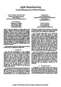
Figure 1: Agile Workcell
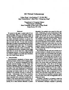
Figure 2: Virtual Workcell
man visual system is well-suited to analyzing graphical representations, we can exploit its capabilities to discover software errors that would be di�cult to detect by other means. When programs are developed to produce new products, they are rst developed and tested on the simulator, and, after critical errors are ltered out the same program is transferred to the actual workcell with few changes (only certain driver routines require change). We call the process of testing control software with graphical simulation virtual testing. It permits many unusual operating scenarios to be tested without causing danger to humans or damage to the real workcell. Figures 1 and 2 show the real workcell and the corresponding virtual workcell.
non-specialists. Examples include: robot teaching in virtual reality[5]; robot target location generation from a CAD model[2]; and making a neutral interface for a portable robot program [3]. Recent research describes new applications of o�-line programming. Freund et al implemented a realistic workcell simulation [6]. Griesmeyer et al provided a framework for validating manufacturing process, in which the same control code can be used both for real and virtual subsystems[7]. We have further extended the concept of manufacturing sequence validation to virtual testing of manufacturing software.
1.2 Previous Research in O�-line Programming
1.3 Scope of Work
The bene ts of o�-line programming in robotics application are well recognized [2, 3, 4]. Two of these advantages may be shared with an agile manufacturing system: �
�
Reduced downtime
O�-line programming allows expensive equipment to continue in production while the next task is being programmed.
Safety
Virtual testing of control software improves robot or human safety by removing dangerous errors before execution of real workcell. Graphical simulation has been widely used for o�-line programming in robotic applications as well as layout design and improving communication between
Our simulator was built on the assumption that workcell downtime can be reduced by developing workcell control software on a simulator and nding logical errors through virtual testing. Although the simulation is not an exact model of the real workcell, it can nevertheless reveal many kinds of errors. The simulator also allows remote testing via a network connection, in which the simulator platform and the control program platform can be separated as much as necessary; hence the latter need not be moved for virtual testing. The simulator does not assume a robot type or a language. Instead, it provides virtual device drivers to the control program so that any program can interact with the simulator. The simulator has also been used for optimizing the assembly sequence, for physical layout concept reviews, and for predicting system performance.
2 Virtual Testing at CWRU 2.1 What is Virtual Testing?
For our purposes, virtual testing is an extension of o�line programming in which the operator can observe a simulated workcell being driven by actual workcell control software. The simulator moves the workcell devices in almost the same way as they move in the real workcell and emulates sensor signals appropriately for each event. These features let the workcell control program drive the virtual workcell and enable almost the same level of testing activity as is possible with a real workcell. Virtual testing is made possible by powerful graphics hardware that can display the workcell events in real-time, by virtual reality ready software (TELEGRIP), and by our unique simulation software architecture. In 3D graphical simulation, the observer can zoom in on a section of the workcell to watch detailed operation, or zoom out for quick overall review. It is possible to follow an object moving around in the virtual workcell. The operator can rotate the workcell or change viewpoints as desired. The animation can be recorded and replayed later.
2.2 Di�culties in Testing Agile Manufacturing Software
In agile manufacturing systems, software testing is dif cult and time-consuming for the following reasons: 1. Long initial setup time The time for setting up an agile manufacturing system and its environment is much longer than for developing a stand-alone program. 2. Reinitialization upon each failure The cleanup activities (hardware and software) after each program failure prohibit fast and repeated tests. 3. Dependency on observation Program behavior is best observed by watching the workcell; logged information may be insu�cient. If a critical situation is lost, previous steps must be re-executed. 4. Team testing Due to the complexity of the workcell, it is tested typically by a team of several people. As well as multiplying labor costs, team management activity increases testing time.
Real Mode Workcell
V M E B U S
Actuator/Sensor
Vision
Real Driver
MV Controller
Robot
Observer MVME167 (VxWorks)
Silicon Graphics Indigo
Virtual Driver Communication Gateway Global Memory
MVME167 (VxWorks)
Robot Vision
Graphical Simulator
Actuator
(GSL)
Sensor
Virtual Mode
Real Mode Virtual Mode
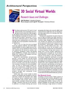
Figure 3: Virtual Testing Architecture 5. Concurrent programs A workcell control program is composed of many concurrent tasks. In our system, for example, 18 tasks run concurrently. This high degree of concurrency makes testing di�cult. Many of these di�culties can be minimized by virtual testing as described in subsequent sections.
2.3 Virtual Testing Architecture
The robots in the workcell are controlled by Adept's MV controller and the control program, written in C++ , executing under VxWorks on an MV167 singleboard computer in a second VMEbus. In the control program, robotic operations are isolated to a few classes. Similarly, the real workcell and virtual workcell drivers can be switched easily by subclassing. The software is not dependent on speci c hardware (e.g. brands of robots or conveyors) and is very portable. Robot commands are delivered to the Adept controller via a dedicated communication link. Mechanical devices are controlled through a dedicated actuator/sensor board which also handles sensor input. In virtual mode, the real drivers are replaced by the virtual drivers. In our object-oriented design, real and virtual drivers are subclasses from a base class providing transparent services to clients. They operate as follows.
�
Virtual Robot Interface
�
Virtual Vision Interface
The virtual driver sends the robot control commands to the simulator's communication gateway (via UNIX sockets) and then returns an acknowledgement. The virtual driver issues vision commands to the vision simulator gateway. The simulator then returns randomly generated part location data back to the control program.
�
Virtual Actuator Interface
�
Virtual Sensor Interface
To simulate the actuation of other mechanisms in the workcell (e.g. conveyors and presses) actuator signals are sent to the communication gateway instead of the actuator/sensor board.
Sensor (input) signals are simulated through the operation of a signal-manager task and a global memory board. The signal-manager is responsible for continually updating the status of signals in global memory. The virtual sensor driver lets the control program read the status of signals from the global memory board instead of from the actuator/sensor board. The simulation program is driven by the Graphical Simulation Language (GSL) provided with TELEGRIP. The simulator implemented by GSL is a static model, but reacts to robot or actuator commands. Robot motion is simulated by moving the corresponding joints. Actuator motion is simulated by moving the device and by producing the appropriate sensor signals. The workcell control program issues commands via the communication gateway which in turn forwards them to the simulator. Sensor signals are issued from the simulator to the control program, via the communication gateway. By isolating the target platform executing the control program, and the simulator platform over a network, it is possible to test the program remotely. Figure 3 shows the overall architecture for virtual testing.
2.4 Steps for Virtual Testing
The following steps are necessary to set up and use a virtual testing system for agile manufacturing 1. Simulator Construction (a) Construct graphical simulation model from a pre-de ned library based on the hardware design.
(b) Build virtual device drivers for robots and other workcell mechanisms. (c) Build a communication gateway for connecting the virtual device drivers to the graphical simulation. (d) Verify the operation of virtual workcell with test programs.
2. Basic Development (a) Estimate robot positions needed for assembly for use during development. (b) Write a workcell control program. (c) Test the program on the simulator (virtual testing). (d) Debug until all logic errors are corrected. 3. Advanced Development (a) Run the control program and simulator for extended periods time to locate more insidious bugs (e.g. counter over-runs and memory leaks) (b) Simulate error conditions. In parallel with software development, precise robot positions are determined from the actual workcell, and part locating routines are developed. 4. Deployment (a) Replace estimated robot positions with accurate numbers. (b) Replace the virtual device drivers with the real drivers. (c) Run the workcell program on the real workcell. (d) Test and debug the workcell program.
3 Analysis of Common Errors in Agile Manufacturing Software
Our ultimate question is: Can the simulator really re-
veal faults in the software? If so, how many and what kind? For the graphical simulator to be most e�ective,
the software faults must be visible as abnormal operations. Reassuringly, in our experience, most program errors were observed during simulator testing and were xed before transferring the software to the real workcell. We will classify the observed errors and analyze their characteristics.
3.1 Types of Errors
1. Collision errors Most collisions errors between robots and other workcell devices are easily revealed by observation: when a collision occurs in the simulator, devices color changes. Since the simulation represents the workcell with reasonable accuracy, avoiding collisions in the simulator certainly helps in avoiding collisions in the real workcell were both operators and hardware are at risk. 2. Sequencing errors These errors are caused by an incorrect work sequence. Since these are controlled by a single thread, most of them are easily detectable. The examples are numerous; a robot movement sequence may be wrong, or multiple devices may operate in the wrong order; a pallet may pass its destination or may be delivered to an incorrect destination; an unintended gripper may be selected to grasp a part. 3. Multitasking errors These errors are caused when tasks do not coordinate as designed. A deadlock is a common example. Deadlocks manifest themselves by halting a certain operation inde nitely. An example might be a pallet stuck during transit because a semaphore was used incorrectly. These are often detectable during more extensive testing, but can also be the cause of intermittent behaviour, making them di�cult to debug. Collisions can occur when a task ends prematurely. For example if the robot control task dies when the robot's gripper is grasping a part on a pallet and another task raises the pallet, a collision occurs, potentially damaging the gripper. 4. Pure software errors No machine control is involved with this type of error. Undetected grammatical errors and pointer errors are good examples. Many of these are visible as illegal pointer accesses or unexpected workcell behavior. 5. Low performance Although this is not technically an error, actions that lead to poor performance can be observed and xed. Examples include a robot waiting for a part even when another part can be grasped and pallets being delivered via ine�cient routes.
3.2 Errors Repaired During Simulator Testing The following are examples of errors that have been observed on the simulator during workcell software development. �
�
�
�
�
�
�
�
Incorrect timing or synchronization (Types
1,2,3) When the work envelope of two devices overlap, incorrect synchronization can cause a collision. In most cases, this error can be observed in the graphical simulation. Commanding wrong robot (Types 1,2) When there are multiple robots, a task may command an unintended robot, which can easily be observed. Using wrong gripper (Types 1,2) The wrong gripper may be selected, or the correct gripper's associated tool transform may be incorrect. This can cause a collision or a mis-grasped part. Incorrect semaphore release order (Type 3) When multiple tasks are waiting on a semaphore, they are released in the order in which they arrived. However the arrival order is nondeterministic, and an unexpected task may get the released semaphore. This type of multitasking error is hard to detect, so repeated testing under various conditions are necessary. Testing on the virtual workcell is especially useful in locating these errors. Uninitialized hardware (Types 1,2) Without proper initialization, some devices may not work correctly or may cause a collision. For example, when a pneumatic slide is in the path of a robot motion, a collision occurs.
Software errors not detected by compiler
(Type 4) Errors like exceeding an array boundary, or using if (a=b) in place of if(a==b), do not reveal themselves immediately. They eventually manifest themselves as symptoms such as misrouting a pallet. No variable initialization (Type 4) Semaphore, variables, and classes may work even when not properly created or initialized. Interface misuse (Type 4) Since the workcell software is programmed by a
team, the usage of some functions may be misunderstood. �
Link error (Type 4)
Incorrectly linked programs can cause errors during operation.
4 Discussion TELEGRIP, or Graphical Simulation in general, is not based on discrete or stochastic modeling. Rather, The model is based on geometric layout, making accurate performance measurements di�cult. Virtual testing has limitations that prevent it from replacing real-world testing. Passing the virtual testing is a necessary condition, but not a su�cient condition, so overdependency on simulator can lead to catastrophes. The simulation itself is merely a software construct and may have its own bugs even with an accurate model. Sometimes it is di�cult to tell if an error is caused by the simulator or the control program. However, the simulator can still signi cantly reduce the amount of eld testing when it is reasonably well built. The animation on a Silicon Graphics Indigo2 shows satisfactory performance with realistic display of workcell operation. The amount saved in reducing workcell down time and avoiding possibly damaging situations can easily justify the costs of graphical workstations and simulator development.
5 Conclusions A virtual testing system for agile manufacturing software using 3D graphical simulation has been developed at CWRU. The same program developed using the virtual workcell can be used on the real workcell, thus reducing development time signi cantly. As we have seen in the examples, most errors in the workcell control software are revealed during testing with the simulator. This makes the simulation a very e�ective tool for o�-line software development.
6 Acknowledgements We are grateful to Chrysanthie Chamis and Scott Ameduri for creating the library of robots and conveyors in TELEGRIP. This work was supported by the Cleveland Advanced Manufacturing Program
(CAMP) through the Center for Automation and Intelligent Systems Research (CAISR) and the Case School of Engineering.
References [1] R.D. Quinn, G.C. Causey, F.L. Merat, D.M. Sargent, N.A. Barendt, W.S. Newman, V.B. Velasco Jr., A. Podgurski, J-Y Jo, L.S. Sterling, Y.H. Kim. \Design of an Agile Manufacturing Workcell for Light Mechanical Applications," Proc. of IEEE International Conference on Robotics and Automation, 1996, pp.858-863.
[2] A. Kochan. \O�ine programming essential to meet robot demand," Industrial Robot, Vol. 22, No. 3, 1995, pp.27-28. [3] L.F. Nielsen, S. Trostmann, E. Trostmann, F.Conrad. \Robot O�-line Programming and Simulation As a True CIME-Subsystem," Proc.
1992 IEEE International Conference on Robotics and Automation, Nice, France, May 1992,
pp.1089-1094. [4] J.F. Quinet. \Calibration for O�ine programming purpose and its expectations," Industrial Robot, Vol. 22, No. 3, 1995, pp.9-14. [5] T. Takahashi and H. Ogata. \Robotic Assembly Operation based on Task-Level Teaching in Virtual Reality," Proceedings of the 1992 IEEE International Conference on Robotics and Automation, Nice, France, May 1992, pp1083-1088. [6] E. Freund, J. Rossmann, J. Utho�, U. van der Valk. \Towards Realistic Simulation of Robotic Workcells," Proceedings of the 1994 IEEE/RSJ/GI International Conference on Intelligent Robots and Systems, vol. 1, 1994, pp.39-46.
[7] Michael J. Griesmeyer and Fred J. Oppel. \Process Subsystem Architecture for Virtual Manufacturing Validation," Proceedings of the 1996
IEEE International Conference on Robotics and Automation, Minneapolis, Minnesota, April 1996,
pp2371-2376.