W IRELESS H EART R ATE M ONITORING & A LERTING D EVICE USING P HOTOPLETHYSMOGRAPHY USING MICROCONTROLLER ARDUINO UNO
Vineel Kaipu
-
[email protected]
Aditya Sinha Trisha Singh Ruhi Singh
Department of Electronics & Communications Engineering Indian Institute of Information Technology, Allahabad
1
1. ABSTARCT In this project we'll be presenting a heart rate monitoring device based on the Photoplethysmography technique, which will wirelessly alert the concerned when an erratic heart rate is detected. Consisting of two devices, the first device is connected to the patient, which measures the heart rate and displays the animated real time PPG (Photoplethysmogram) wave and BPM (Beats per Minute). If any erratic data is recorded the interfaced microprocessor will immediately send an alerting signal wirelessly to the second device. The second device which is carried by the doctor’s/nurse’s will always display the real time Heart rate (BPM) sent to it by the first device and foremost, will also alert the person when it receives an alerting signal from the microprocessor. The operating range of this device will be confined to the walls of the hospital.
2. MOTIVATION Heart Rate alerting device are quickly becoming ubiquitous in our daily live. In this age of information, the more we know about our health status, the better prepared we are to take good care of ourselves, seek medical attention when necessary, and push our physical limits through vigorous exercise regimens. Naturally, electronics play a big role in the implementation of most heart rate monitors, along with sophisticated algorithms designed to analyse and display the pertinent details. Using the technique of photoplethysmography a cheaper, very efficient and reliable measure of heart rate is possible. Our main motivation to make such a device is because it will be very handy as ECG alarms are often unheard or left unnoticed.
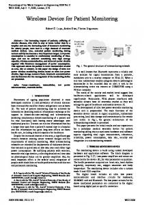
3. WORKING OF THE PROJECT The sensing device is based on the principle of Photoplethysmography (PPG). This technique measures the variation in blood volume in tissues using a light source and a detector. Since the change in blood volume is synchronous to the heartbeat, this technique can be used to calculate the heart rate.
2
Figure 2: Illustrative picture showing the changes in the transmitted wave according to the blood flow.
The light is cast by IR Diode into the tissue/ finger and the amount of reflected light is measured by the phototransistor. The phototransistor convert the incident light into an electrical response. This electrical response or voltage is directly proportional to the amount of light falling on the transistor. Since the detected light reflected from the body part will fluctuate according to the pulsatile blood flow caused by the beating of the heart, we get a weak PPG signal from the output of the transistor.
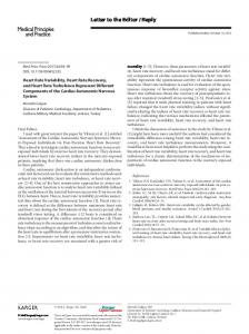
The PPG signal consists of a large DC component, which is attributed to the total blood volume of the examined tissue, and a pulsatile (AC) component, which is synchronous to the pumping action of the heart. The AC component, which carries vital information including the heart rate, is much smaller in magnitude than the DC component.
3
Figure 3: An approximate waveform which is expected from the sensor
To remove this DC component, the signal is passed through a passive (RC) highpass filter (HPF) in the first stage of amplification and filtering.
Figure 4: The sensor circuit 4
This PPG signal will be very weak and noisy. So we need an amplifier and filter out the signal before feeding it into the microprocessor to find the heart rate.
Figure 5: STAGE 1- FILTERING & AMPLIFICATION
In Stage I Filtering and Amplification, the input signal is first passed through a passive high-pass filter (HPF) to block the DC component of the PPG signal. The cut-off frequency of the HPF is 0.5Hz .The output from the HPF goes to an Opampbased active low-pass filter (LPF), where the cut-off frequency is set to 3.4Hz. The output from the active LPF now goes into Stage II filtering and amplification.
5
Figure 6: STAGE 2- FILTERING & AMPLIFICATION
Stage 2 circuit is basically a replica of the Stage I circuit. And a second stage of amplification and filtering is required so that the highest degree of the cleansing of signal I achieved.
These PPG waves are passed into the Arduino microprocessor, where the BPM is calculated and displayed on the Laptop screen using Processing environment.
5. SCHEMATIC DIAGRAM OF WORKING MODEL The following represents the block diagram of the project The signal from the sensor goes through two stages of filtering and amplification and gets fed into an Arduino. In the Arduino the algorithm for transmitting, calculating and displaying the BPM and PPG wave is written which will be executed.
6
Figure 7: TRANSMITTING BLOCK DIAGRAM:
Figure 8: RECEIVING BLOCK DIAGRAM
7
6. FLOW CHART The process flow of the coding of the project goes like this
FLOWCHART Start Set pin Modes Set Baud Rate
No
Is Pulse Flag set Yes
Print BPM and Signal
INTERRUPT
Reset pulse flag
ISR (2ms)
Set fade rate Decrease fade rate Write output to fade pin Delay 20 ms
This main program is interrupted by an interrupt program every 2ms to check for a Heart Beat and also sample the signal. Thus whenever an Interrupt is requested the following ISR (Interrupt Service Routine) is executed.
8
ISR ( Interrupt Service Routine) – 2ms frequency
9
7. FUTURE SCOPE & APPLICATIONS
As ECG alarms are often unheard or left unnoticed such a device would prove to be very useful in alerting the doctors The doctor/nurse can keep a track of his vitals without having to go to his room every time. An interactive application can also be designed which can not only be accessed by the doctors/nurses but also by their family members.
This project can be expanded into giving out other information like, concentration of oxygen in the blood etc. The transmitting part can be modified into a simple wearable/stable daily device for monitoring one’s own Heart rate which can also maintain a log of his data.
8. ADVANTAGES & LIMIATATIONS Advantages 1. Since it is wireless so the doctor/nurse can keep a track of his vitals without having to go to his room every time. 2. It sensors are very cheap and efficient. 3. When the hospital is low on staff, this device will prove to be very useful.
Limitations 1. The Sensing part is very motion sensitive. 2. The noise is not completely eliminated.
10
9. PROTOTYPE PICTURES https://www.youtube.com/watch?v=hRHFTOsOiRQ – A video made on the project
Figure 9: SENSOR
Figure 10: TRANSMITTING CIRCUIT
11
Figure 11: RECEIVING CIRCUIT
Figure 12: PROCESSING DISPLAY:
12
10. REFERENCES http://ieeexplore.ieee.org/stamp/stamp.jsp?tp=&arnumber=5478989&tag=1 http://ieeexplore.ieee.org/stamp/stamp.jsp?tp=&arnumber=6179054 http://electronicdesign.com/digital-ics/build-wrist-heart-rate-monitor-using-ultra-low-powermcu http://embedded-lab.com/blog/?p=1671 http://embedded-lab.com/blog/?p=7485 http://www.edn.com/design/medical/4434616/Simple-pulse-oximetry-for-wearable-monitor http://embedded-lab.com/blog/?p=7336 http://embedded-lab.com/blog/?p=7400 https://www.picotech.com/library/experiment/calculating-heart-rate https://www.fairchildsemi.com/application-notes/AN/AN-3005.pdf http://www.engineersgarage.com/electronic-components/l14g2 http://pulsesensor.com/pages/pulse-sensor-amped-arduino-v1dot1 http://forum.processing.org/two/discussion/8246/processing-code-to-display-ampedvisualizer http://www.jeremyblum.com/2010/09/05/driving-5-speakers-simultaneously-with-an-arduino/ http://www.instructables.com/id/Arduino-Timer-Interrupts/?ALLSTEPS http://pulsesensor.com/pages/pulse-sensor-speaker-tutorial https://sites.google.com/site/qeewiki/books/avr-guide/timers-on-the-atmega328 https://sites.google.com/site/qeewiki/books/avr-guide/common-timer-theory https://sites.google.com/site/qeewiki/books/avr-guide/interrupts http://www.atmel.com/images/Atmel-8271-8-bit-AVR-Microcontroller-ATmega48A-48PA88A-88PA-168A-168PA-328-328P_datasheet_Complete.pdf http://en.wikipedia.org/wiki/Heart_rate http://en.wikipedia.org/wiki/Photoplethysmogram https://www.youtube.com/watch?v=2v3rae-73jc http://www.arduino.cc/en/Reference/Board
13