metals Article
Effect of Austempering Time on the Microstructure and Carbon Partitioning of Ultrahigh Strength Steel 56NiCrMoV7 Quanshun Luo *, Matthew Kitchen and Shahriar Abubakri Materials and Engineering Research Institute, Sheffield Hallam University, Howard Street, Sheffield S1 1WB, UK;
[email protected] (M.K.);
[email protected] (S.A.) * Correspondence:
[email protected]; Tel.: +44-114-2253649 Received: 23 May 2017; Accepted: 3 July 2017; Published: 7 July 2017
Abstract: Ultrahigh strength steel 56NiCrMoV7 was austempered at 270 ◦ C for different durations in order to investigate the microstructure evolution, carbon partitioning behaviour and hardness property. Detailed microstructure has been characterised using optical microscopy and field emission gun scanning electron microscopy. A newly developed X-ray diffraction method has been employed to dissolve the bainitic/martensitic ferrite phase as two sub-phases of different tetragonal ratios, which provides quantitative analyses of the carbon partitioning between the resultant ferrites and the retained austenite. The results show that, a short-term austempering treatment was in the incubation period of the bainite transformation, which resulted in maximum hardness being equivalent to the oil-quenching treatment. The associated microstructure comprises fine carbide-free martensitic and bainitic ferrites of supersaturated carbon contents as well as carbon-rich retained austenite. In particular, the short-term austempering treatment helped prevent the formation of lengthy martensitic laths as those being found in the microstructure of oil-quenched sample. When the austempering time was increased from 20 to 80 min, progressive decrease of the hardness was associated with the evolution of the microstructure, including progressive coarsening of bainitic ferrite, carbide precipitating inside high-carbon bainitic ferrite and its subsequent decarbonisation. Keywords: ultrahigh strength steel; austempering; carbon partitioning; carbide precipitation; bainitic/martensitic ferrite
1. Introduction Low alloy ultrahigh strength steels are key structural materials for load-bearing components of large vehicles and aircrafts [1–3]. In addition to the conventional strengthening treatments of quenching and tempering (QT) and bainitic salt bathing process, a new treatment has been developed by lowering the salt bath temperature to a level close to, or even lower than, the Ms (martensite starting) temperature [4–10]. The resultant microstructure comprises extremely fine ferrite laths and inter-lath filmy austenite, both having super-saturated carbon contents because of the prohibition of carbide precipitation. Such ferrite based microstructure enables ultrahigh strength properties, e.g., 2.5 GPa of compression strength and 2.3 GPa of ultimate tensile strength. However, such a process needs a very long salt bath time, and concern also arises from the low toughness property [5,6,11]. When an austempering treatment is applied, wherein the austenised steel is firstly soaked for a short period in a salt bath of lower-bainite transformation and is subsequently quenched to room temperature, the resultant microstructure is a mixture of bainite, martensite and retained austenite [3,12–17]. The new heat treatments were reported to bring about higher hardness and strength properties than the QT treatments, while the strengthening mechanisms have not been fully understood up to date. Tomita and co-workers attributed the increased strength properties to several Metals 2017, 7, 258; doi:10.3390/met7070258
www.mdpi.com/journal/metals
Metals 2017, 7, 258
2 of 14
factors, including martensite grain refining, due to partitioning of austenite by bainitic ferrite prior to martensite transformation, the predominant role of the major martensite plates, and strain-hardening of the bainitic ferrite, induced by the martensite transformation [18]. These explanations were also adopted by other researchers [13,16–18]. However, the contribution of supersaturated carbon to hardening was excluded in this model. In recent years, increasing attention has been paid on the role of carbon in steel strengthening. Supersaturated carbon is highly involved in several strengthening mechanisms of ultrahigh strength steels, regardless of the transformation kinetics [19–21]. In the transformation from austenite to martensite or bainite, carbon is known to diffuse from newly formed martensite or bainite to the parent austenite. This phenomenon, known as carbon partitioning, has been utilised to develop a novel toughening treatment, i.e., the so-called quenching and partitioning (Q–P) treatment [22–25]. Although carbon partitioning as a general phenomenon was noticed a long time ago [2,26], it is in the Q–P process that the phenomenon was used the first time to control the transformed microstructure [22]. In a recent project, we worked on austempering treatments of a Cr–Ni–Mo–V alloyed spring steel, which led to superior mechanical properties, including ultimate tensile strength of 2100 MPa, yielding strength of 1800 MPa and elongation of 8–10%, along with V-notched Charpy impact toughness of 9–12 J/cm2 [27,28]. This paper reports the microstructure characterisations of a series of austempered samples, with a focus on the carbon partitioning behaviour at various isothermal soaking times. 2. Experimental The sample material was vacuum-re-melted steel and provided as a 50 mm diameter hot-rolled bar with nominal chemical compositions (in wt %) of C 0.55, Si 0.30, Mn 0.76, P 0.014, S 0.0037, Ni 1.69, Cr 1.05, Mo 0.50, V 0.08, and Fe in balance. The Ac3 , Ac1 and Ms temperatures of the steel are estimated to be 780, 715, and 240 ◦ C respectively, as provided by the steel supplier (Böhler Tool Steel & High Speed Steel, Oldbury, UK). The bar was cut as block samples of 20 mm × 10 mm × 8 mm in size for austempering heat treatments. In the heat treatments, the samples were heated in the first salt bath to soak at 850 ◦ C for 30 min. Then they were moved immediately to the second salt bath to soak at 270 ◦ C (i.e., 30 ◦ C above the Ms , at the range of lower bainite transformation) for a selected time before air-cooling to room temperature. The austempering soaking times were selected to be 5, 10, 20, 40 and 80 min. The austempered samples were mounted, and manually ground to remove a surface layer of about 0.3 mm in thickness using coarse SiC abrasive paper (grade 120 #). Then fine grinding was applied using SiC abrasive papers of grades 240 and 600 # for hardness testing. Vickers hardness tests were undertaken at an indenting load of 30 kg. Five indents were made on each sample to calculate the average hardness and the standard deviation. Then following metallographic grinding and polishing, the samples were etched using a 2%-nital etchant before microstructure characterisations using optical microscopy (OPM, Olympus BX51, Tokyo, Japan), scanning electron microscopy (SEM) and X-ray diffraction (XRD). A FEI Nova200 field emission gun (FEG, Eindhoven, The Netherlands) SEM was employed, where the field emission gun provides a spatial resolution of 1.8 nm, being sufficient to resolve nano-scale structural features. A X’Pert X-ray diffractometer (PANalytical, Almelo, The Netherlands) with Cu-Kα radiation (wavelength λ = 0.15406 nm) was employed in the study. On each sample, five diffraction peaks were acquired under the θ–2θ (Bragg-Brentano) mode, including the austenite peaks (200)γ , (220)γ and (311)γ , and the ferrite peaks (200)α and (211)α . The obtained diffractions were measured using a self-developed Gaussian peak-fitting technique to determine the peak position (2θ), net intensity (I) and broadening width (β) (FWHM, the full-width at half maximum) [27,28]. These parameters were then used to calculate the volume fraction (V γ ) and carbon content (Cγ ) of retained austenite and the micro-strains (ε) of both the martensitic and bainitic ferrite and the retained austenite. The equations for the calculations were adapted from literature [29,30].
Metals 2017, 7, 258
3 of 14
V γ = Iγ × (Iγ + G × Iα )−1
(1)
Cγ = (aγ − 0.3555)/0.0044
Metals 2017, 7, 258
3 of 13
ε = 0.25Vγ×= Iβγ ××(Icosθ × sinθ −1 γ + G × Iα)−1
(1)
(2) (3)
In Equation (2), aγ stands for the austenite parameter, which is an average of three Cγ = (aγ −lattice 0.3555)/0.0044 (2) lattice parameter values derived from the (200)εγ=, 0.25 (220) and (311) measurements. The (200) diffraction γ γ α −1 × β × cosθ × sinθ (3) peak was numerically processed more extensively using a newly developed quantitative method. In Equation (2), aγ stands for the austenite lattice parameter, which is an average of three lattice Details of the new method have been described elsewhere [31]. The new analytical method considers parameter values derived from the (200)γ, (220)γ and (311)γ measurements. The (200)α diffraction peak martensite a hardened medium-carbon steelusing as a amixture of lath- and plate-martensites, whereas wasin numerically processed more extensively newly developed quantitative method. Details the two martensite sub-phases are known to have different tetragonal ratios because of their different of the new method have been described elsewhere [31]. The new analytical method considers martensite in a hardened medium-carbon steel as a mixture of lath- and plate-martensites, whereas carbon contents. the two martensite sub-phases are known to have different tetragonal ratios because of their different carbon contents. 3. Results 3. Results 3.1. Hardness Property of Austempered Samples 3.1. Hardness Property of Austempered Samples Figure 1a shows the effect of austempering time on the hardness property. When a short-time austempering was1aapplied, the steel a high level of hardness, being even slightly higher Figure shows the effect of remained austempering time on the hardness property. When a short-time than theaustempering as-quenched sample 679).remained The maximum hardness of HV was measured was applied,(HV the steel a high level of hardness, being716 even slightly higher in the thanwas the as-quenched sample 679). Thefurther maximum hardnessaustempering of HV 716 wastime measured in the sample that austempered for 10(HV min; then, increased from 10 to 40 min sample that was austempered for 10 min; then, further increased austempering time from 10 to 40 when resulted in remarkably decreased hardness. Following that, the hardness stabilised in that level min resulted in remarkably decreased hardness. Following that, the hardness stabilised in that level the austempering time was extended to 80 min. These results suggest that a short period of isothermal when the austempering time was extended to 80 min. These results suggest that a short period of treatment did nottreatment soften the while steel became softer softer whenwhen the treatment isothermal didsteel, not soften thethe steel, while the steelsubstantially became substantially the was longer. treatment was longer.
(a)
(b)
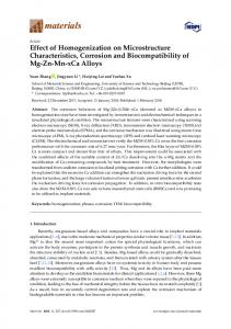
Figure 1. Effect of austempering time on (a) the hardness property of the sample steel and (b) the
Figure 1. Effect of austempering time on (a) the hardness property of the sample steel and (b) the lattice strains of the martensitic and bainitic ferrites. lattice strains of the martensitic and bainitic ferrites. Figure 1b illustrates the variation of overall lattice strains of the martensitic and bainitic ferrites as determined by XRD peak broadening analyses. Firstly, both diffraction (200) α Figure 1b illustrates the variation of overall lattice strains of the theoverall martensitic and peaks bainitic ferrites as and (211)α were analysed to calculate the lattice strains along the and directions. Then by determined by XRD peak broadening analyses. Firstly, both the overall diffraction peaks (200)α Gaussian separation of the (200)α peak as sub-peaks, the martensitic or bainitic ferrite was considered and (211) were analysed to calculate latticeratios, strains along themartensite and directions. asαtwo sub-phases having different the tetragonal namely lath (Mlath ) and plate Then bymartensite Gaussian(Mseparation of the (200) peak as sub-peaks, the martensitic or bainitic plate) [31]. Consequently the α lattice strains of the Mlath and Mplate sub-phases can be ferrite estimated. The analyses reveal correlation betweentetragonal the hardnessratios, property and the lattice strains of (Mlath ) was considered as two sub-phases having different namely lath martensite the martensitic and bainitic ferrite, which is consistent with the knowledge that martensitic and plate martensite (Mplate ) [31]. Consequently the lattice strains of the Mlath and Mplate sub-phases transformation is the predominant hardening mechanism. The strains decrease gradually with can be estimated. The analyses reveal correlation between the hardness property and the lattice increasing austempering time. The calculated strain, consistent with the hardness property, can be strains ofattributed the martensitic and bainitic ferrite, which is consistent with the knowledge that martensitic to both the recovery of defects and the ferrite decarbonisation as a result of carbide transformation is the predominant hardening mechanism. The strains decrease with precipitation. Moreover, in the ferritic sub-phases, the higher micro-strain values of the Mgradually plate reveal increasing austempering time. The calculated strain, consistent with the hardness property, can its substantially higher lattice distortion than the Mlath.
be attributed to both the recovery of defects and the ferrite decarbonisation as a result of carbide
Metals 2017, 7, 258
4 of 14
precipitation. Moreover, in the ferritic sub-phases, the higher micro-strain values of the Mplate reveal its substantially higher lattice distortion than the Mlath . 3.2. Microstructure Observed in Optical Microscopy Metals 2017, 7, 258
4 of 13
In OPM observations, bainitic ferrite was easily recognised as black acicular grains. The OPM Microstructure Observed Optical Microscopyof the martensitic and bainitic microstructure with images 3.2. displayed in Figure 2 in show variation increasing austempering time. The oil-quenched was known to have predominantly martensitic In OPM observations, bainitic ferrite was sample easily recognised as black acicular grains. The OPM images displayed Figure some 2 show variation of acicular the martensitic bainitic microstructure withcontrast structure, whereas it alsoinshows black-etched grainsand similar to bainite. The black austempering time. The oil-quenched samplewhich was known to have predominantly in theseincreasing acicular grains suggests fine carbide precipitates, has been confirmed in subsequent martensitic structure, whereas it also shows some black-etched acicular grains similar to bainite. The SEM observations at higher magnification, to be discussed later in Figure 3. The sample austempered black contrast in these acicular grains suggests fine carbide precipitates, which has been confirmed in 5 mininexhibits mostly martensiticatmicrostructure, comparable to thelater oil-quenched sample, as shown subsequent SEM observations higher magnification, to be discussed in Figure 3. The sample in Figure 2a,b. When austempering was increased to 10 and 20 min,tothe shows a mixed austempered in the 5 min exhibits mostlytime martensitic microstructure, comparable thesteel oil-quenched microstructure ofshown bainiteinand martensite where the amounttime of bainite increases themin, austempering sample, as Figure 2a,b. When the austempering was increased to 10with and 20 the steel shows microstructure of bainite and martensite the amount of bainite time, (Figure 2c,d).a mixed In Figure 2c,d, the bainite regions exhibit where black contrast because of increases the preferential thebainite austempering (Figure 2c,d). Figure 2c,d, the bainite regionsand exhibit black contrast etchingwith of the grainstime, as compared toInthe martensite. The bainite martensite regions are because of the preferential etching of the bainite grains as compared to the martensite. The bainite labelled “B” and “M”, respectively. and martensite regions are labelled “B” and “M”, respectively.
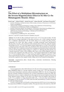
Figure 2. Optical micrographs of samples after 270 °C austempering treatment for various durations:
Figure 2. micrographs 270(e)◦ C40austempering treatment for various durations: (a)Optical oil-quenched; (b) 5 min; of (c) samples 10 min; (d)after 20 min; min; and (f) 80 min. (a) oil-quenched; (b) 5 min; (c) 10 min; (d) 20 min; (e) 40 min; and (f) 80 min. The samples being austempered by 40 and 80 min are similar to each other and exhibit a relatively homogeneous contrast, because that bainitic transformation had taken place in the whole
Metals 2017, 7, 258
5 of 14
The samples being austempered by 40 and 80 min are similar to each other and exhibit a relatively homogeneous contrast, because that bainitic transformation had taken place in the whole volume, as shown in2017, Figure Metals 7, 258 2e,f. The change from heterogeneous to homogeneous microstructure suggests 5 of 13 that the bainite transformation was completed in an intermediate time between 20 and 40 min, whereas volume, as shown in Figure 2e,f. The change from heterogeneous to homogeneous microstructure furthersuggests soakingthat after completion did notwas give rise to noticeable change in thebetween optical microstructure. thethe bainite transformation completed in an intermediate time 20 and 40 The observations suggest that, bainitedid transformation did not take place the initial min,OPM whereas further soaking after the completion not give rise to noticeable change in thein optical short microstructure. period, indicating the existence of a bainitic incubation period, as suggested by other OPM observations suggestwork, that, bainite transformation not take place intook the initial short researchersThe [32–34]. In the current noticeable bainitedid transformation place after an period, indicating the existence of a bainitic incubation period, as suggested by other researchers [32– incubation period of less than 10 min and, after that, significant austenite to bainite transformation 34].with In theincreasing current work, noticeable occurred soaking time.bainite transformation took place after an incubation period of less than 10 min and, after that, significant austenite to bainite transformation occurred with In addition, the OPM observations also suggest heterogeneous distribution of the bainitic structure. increasing soaking time. In Figure 2c,d, the bainite-rich regions exhibits black contrast as compared to the martensite-rich regions, In addition, the OPM observations also suggest heterogeneous distribution of the bainitic in which initial formed the dendritic stems C–Cr–Mo contents structure. bainite In Figure 2c,d, preferentially the bainite-richin regions exhibits blackwhere contrast as compared to are the lower than the inter-dendritic areas.inThe structural heterogeneity arose from in the martensite-rich regions, which initial bainite formed preferentially thedendritic dendriticsegregation stems where of the contents are lower than the inter-dendritic areas. and The was structural heterogeneity fromrolling. as-castC–Cr–Mo steel. Such segregation was developed in the casting retained even afterarose the hot the dendritic segregation of the as-cast steel. Such segregation was developed in the casting and was Similar structural heterogeneity was also reported in other low alloy steels [35]. retained even after the hot rolling. Similar structural heterogeneity was also reported in other low alloy steels [35]. 3.3. Microstructure Observed in Scanning Electron Microscopy
In3.3. Figure 3a,b, the microstructures of the Microscopy 5 min austempered and oil-quenched samples are Microstructure Observed in Scanning Electron compared IntoFigure each 3a,b, otherthe at microstructures low magnification imaging, both showing as a mixture of lath- and of the 5 min austempered and oil-quenched samples are plate-shape martensites. In drawing comparisons between Figure 3a,b, martensites austempered compared to each other at low magnification imaging, both showing as the a mixture of lath- of and platesteel are more uniform and also slightly smaller in grain size. The comparison may reveal grain shape martensites. In drawing comparisons between Figures 3a,b, the martensites of austempered refining byare means the short pre-treatment. Previously, researchers have grain attributed steel moreof uniform andaustempering also slightly smaller in grain size. The comparison may reveal refining by means of increased the short austempering pre-treatment. Previously, researchers have attributed the grain refining to the ferrite nucleation sites [32–35]. They described such short-range refining to in thethe increased nucleation sitesas [32–35]. Theydecomposition, described such short-range motiontheofgrain carbon atoms bainiteferrite incubation period spinodal which resulted motion of carbon atoms in the bainite incubation period as spinodal decomposition, which resulted in nano-scale heterogeneous distribution of carbon atoms to fertilise nucleation of ferrite in the in nano-scale heterogeneous distribution of carbon atoms to fertilise nucleation of ferrite in the carbon-depletion domains. carbon-depletion domains.
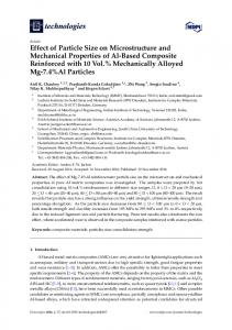
Figure 3. Field emission gun scanning electron microscopy (FEG-SEM) images of (a,c) the oil-
Figurequenched 3. Field emission gun scanning electron microscopy sample and (b,d) the 5 min austempered sample.(FEG-SEM) images of (a,c) the oil-quenched sample and (b,d) the 5 min austempered sample.
Metals 2017, 7, 258
6 of 14
Details of the microstructure constituents are presented at high magnification in Figure 3c,d, in which the lath- and plate-shape martensites are labelled. Observations at higher magnifications showed that, some coarse martensite grains contain extremely fine particles, indicative of carbide precipitation, e.g., in the grains labelled ”X”. Such precipitation is more pronounced in the oil-quenched Metals 2017, 7, 258 6 of 13 sample, which is shown in Figure 3c. On the other hand, most of the martensite grains of the Details of the microstructure constituents are presented at high magnification in Figure 3c,d, in austempered sample are free from carbide precipitation, as shown in Figure 3d. which the lath- and plate-shape martensites are labelled. Observations at higher magnifications In showed addition, small of un-dissolved carbide particles can also be observed. that, somequantities coarse martensite grains contain extremely fine particles, indicative of carbideAt high magnification, thesee.g., particles havelabelled a round and disperse heterogeneously precipitation, in the grains ”X”.shape Such precipitation is more pronounced in in thethe oil- matrix, quenched sample, which is shown in Figure 3c. On the other hand, most of the martensite of as labelled “Carbides” in Figure 3c,d. The presence of un-dissolved carbides wasgrains attributed to the austempered sampleofare free from carbide precipitation, as shown in Figure 3d. In the heat treatment, insufficient decomposition the cementite grains in the austenisation stage. In addition, small quantities of un-dissolved carbide particles can also be observed. At high the samples were heated to 850 ◦ C and kept isothermally at that temperature for 30 min. The holding magnification, these particles have a round shape and disperse heterogeneously in the matrix, as time was not long enough in to Figure have all the The cementite carbide grains dissolve in was the austenite labelled “Carbides” 3c,d. presence of un-dissolved carbides attributed matrix. to In insufficient a set of low-magnification SEM images, Figure 4 illustrates the bainitic grain growth with decomposition of the cementite grains in the austenisation stage. In the heat treatment, the samples were heated to 850 and kept at that temperature 30 min. The holding increasing austempering time. In°CFigure 4a,isothermally the 10 min treated sampleforexhibits a heterogeneous time was not long enough to have all the cementite grains in the austenite matrix. located distribution of lathand plate-shape martensite orcarbide bainite. Thedissolve laths are fine and narrow, In regions a set of low-magnification SEM images, Figure carbide 4 illustrates the bainitic grain growth withregions mostly in the containing un-dissolved nodular particles. In contrast, the rest increasing austempering time. In Figure 4a, the 10 min treated sample exhibits a heterogeneous show relatively coarse ferritic leaves, (the lightly etched, labelled “B”). These leaves are believed to distribution of lath- and plate-shape martensite or bainite. The laths are fine and narrow, located be carbide-free ferrite by comparing them to the grainparticles. coarsening and carbide precipitation mostly inbainitic the regions containing un-dissolved nodular carbide In contrast, the rest regions in similar regions. Nevertheless, sample still shows grain size. Significant coarsening show relatively coarse ferritic the leaves, (the lightly etched, fine labelled “B”). These leaves are grain believed to be carbide-free ferrite by time comparing to the grain and carbide precipitation happened when the bainitic austempering was them increased to 20coarsening and 40 min, as shown in Figure 4b,c. in 4b, similar Nevertheless, the mixtures sample stillofshows fine martensite grain size. Significant grain In Figure the regions. less-etched blocks are acicular or bainite andcoarsening blocky retained happened when the austempering time was increased to 20 and 40 min, as shown in Figure 4b,c. In austenite (labelled “A”). A few small needle-like ferrite grains (labelled with an arrow) can be found Figure 4b, the less-etched blocks are mixtures of acicular martensite or bainite and blocky retained inside aaustenite blocky austenite grain, implying fine martensite plates growing inside partitioned austenite, (labelled “A”). A few small needle-like ferrite grains (labelled with an arrow) can be found which isinside consistent the grain mechanism by Tomita [3]. In Figure 4c, bainitic a blockywith austenite grain, refining implying fine martensiteproposed plates growing inside partitioned austenite, ferrite becomes the dominant structural component in the 40 minby treated and the which is consistent with the grain refining mechanism proposed Tomitasample [3]. In Figure 4c, inter-granular bainitic ferrite becomes the less. dominant component in thetime 40 min sample the in interaustenite has been much Whenstructural the isothermal soaking wastreated increased to and 80 min Figure 4d, granular austenite has been much less. When the isothermal soaking time was increased to 80 min in filmy the whole image is almost full of bainitic ferrite grains, except for some very narrow inter-lath Figure 4d, the whole image is almost full of bainitic ferrite grains, except for some very narrow interaustenite, as well as un-dissolved carbide particles. lath filmy austenite, as well as un-dissolved carbide particles.
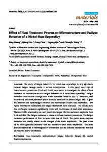
Figure 4. Low-magnification FEG-SEM images of samples austempered for different durations: (a) 10
Figure 4. FEG-SEM images ofgrowth samples austempered for different durations: min;Low-magnification (b) 20 min; (c) 40 min; and (d) 80 min. Note the of bainitic ferrite. (a) 10 min; (b) 20 min; (c) 40 min; and (d) 80 min. Note the growth of bainitic ferrite.
Metals 2017, 7, 258
7 of 14
Metals 2017, 258 7 ofcan 13 see Figure 5 7,shows evolution of the microstructure at high magnification, wherein one the growth of carbide precipitates inside the bainitic ferrite grains. In Figure 5a,b, the 10 Figure 5 shows evolution of the microstructure at high magnification, wherein one can see the and 20 min treated samples show a mixture bainiteferrite (labelled containing carbide growth of carbide precipitates inside theofbainitic grains.“B”, In Figure 5a,b, the 10 andprecipitates) 20 min and martensite (labelled precipitate-free). In Figure some bainite grains containand carbide treated samples show“M”, a mixture of bainite (labelled “B”,5c, containing carbide precipitates) martensite (labelled precipitate-free). InFigure Figure5b, 5c,whereas some bainite carbide precipitates which are as“M”, fine as those shown in othersgrains show contain coarse precipitates. precipitates are as fine asshows those shown in Figurecoarsened 5b, whereas others show It coarse precipitates. In Figure 5d, thewhich microstructure significantly precipitates. is believed that, the In Figure 5d, the microstructure shows significantly coarsened precipitates. It is believed thefrom carbide coarsening followed the diffusion kinetics, i.e., taking place by absorbing carbonthat, atoms carbide coarsening followed the diffusion kinetics, i.e., taking place by absorbing carbon atoms from the ferrite matrix. As a result, the carbon content of the ferrite should be gradually lower, leading to the ferrite matrix. As a result, the carbon content of the ferrite should be gradually lower, leading to decreased micro-straining, as shown in Figure 1b, and decreased lattice tetragoneity. This has been decreased micro-straining, as shown in Figure 1b, and decreased lattice tetragoneity. This has been confirmed by the XRD analysis as described below. confirmed by the XRD analysis as described below.
Figure 5. High-magnification FEG-SEM images of samples austempered for different durations: (a)
Figure 5. High-magnification FEG-SEM images of samples austempered for different durations: 10 min; (b) 20 min; (c) 40 min; and (d) 80 min. Note the growth of bainitic ferrite. (a) 10 min; (b) 20 min; (c) 40 min; and (d) 80 min. Note the growth of bainitic ferrite.
3.4. Results of X-ray Diffraction Analyses
3.4. Results of X-ray Diffraction Analyses Figure 6 shows the collected diffraction peaks of both the austempered and oil-quenched samples.6Ashows quick comparative viewdiffraction reveals that peaks the oil-quenched sample exhibits the maximum peak Figure the collected of both the austempered and oil-quenched broadening, whereas the peaks of the austempered samples become increasingly sharper with samples. A quick comparative view reveals that the oil-quenched sample exhibits the maximum increasing austempering time, indicative of the variation of lattice distortion. Meanwhile, retained peak broadening, whereas the peaks of the austempered samples become increasingly sharper with austenite peaks are visible in most cases. However, the as-quenched sample does not present the increasing austempering time, indicative of the variation of lattice distortion. Meanwhile, retained maximum intensities in the austenite peaks, which would suggest increased austenite following the austenite peaks are visible in most cases. However, the as-quenched sample does not present the austempering treatments. maximum intensities in the austenite peaks, which would suggest increased austenite following the austempering treatments.
Metals 2017, 7, 258 Metals 2017, 7, 258
8 of 14 8 of 13
Figure 6. X-ray diffraction (XRD) peaks of the retained austenite and martensitic/bainitic ferrite phases.
Figure 6. X-ray diffraction (XRD) peaks of the retained austenite and martensitic/bainitic ferrite phases.
Valuable results on the microstructure characteristics have have been from thethe quantitative Valuable results on the microstructure characteristics beenobtained obtained from quantitative analyses of these diffraction patterns, including the volume fraction, carbon content and micro-strain analyses of these diffraction patterns, including the volume fraction, carbon content and micro-strain of of retained austenite twooftypes of ferritic sub-phases. Detailed consideration of the ferritic subretained austenite and twoand types ferritic sub-phases. Detailed consideration of the ferritic sub-phases phases can be found in a recent publication [31], namely, that the mixture of martensite and bainite can be found in a recent publication [31], namely, that the mixture of martensite and bainite structure structure have been treated as two martensitic sub-phases (Mplate and Mlath) of different tetragonal have been treated as two martensitic sub-phases (Mplate and Mlath ) of different tetragonal ratios; ratios; although, a limitation of the method was that it was not capable of separating the austemperinalthough, a limitation of the thequenching-formed method was that martensites. it was not capable separating the austemperin-formed formed bainite and Figure 7ofshows an example of separation of bainitetheand thediffraction quenching-formed martensites. Figure 7 shows anpeak-fitting example of separation of the ferrite peak (200)α as four sub-peaks using the Gaussian technique, where ferritepeaks diffraction (200) as four sub-peaks using the Gaussian peak-fitting technique, where 1 and 2 peak represent the M plate diffractions and peaks 3 and 4 represent the M lath diffractions. Then α integrated intensity, peak and FWHM value3 of each sub-peak can to peaks the 1 and 2 represent the M diffractions and peaks and 4 represent thebe Mmeasured plateposition lath diffractions. calculate the crystalline characteristics. The results are shown in Figure 8. Then the integrated intensity, peak position and FWHM value of each sub-peak can be measured to calculate the crystalline characteristics. The results are shown in Figure 8.
Figure 7. Multiple Gaussian peaking fitting to separate the (200)α peak as four sub-peaks of the Mplate and Mlath sub-phases as labelled: 1—(200) of Mplate, 2—(002) of Mplate, 3—(200) of Mlath, and 4—(002) of Mlath.
Figure 7. Multiple Gaussian peaking fitting to separate the (200)α peak as four sub-peaks of the Mplate and Mlath sub-phases as labelled: 1—(200) of Mplate , 2—(002) of Mplate , 3—(200) of Mlath , and 4—(002) of Mlath .
Metals 2017, 7, 258 Metals 2017, 7, 258
9 of 14 9 of 13
Figure 8. Quantified results XRDanalyses: analyses: Effect Effect of time on on thethe volume fraction, Figure 8. Quantified results of of XRD of austempering austempering time volume fraction, carbon content and lattice strain of the matrix phases. carbon content and lattice strain of the matrix phases.
Figure 8 illustrates the effect of austempering time on the variation of volume fraction and
Figure illustrates the of austempering time onInthe variation of volume and carbon carbon 8concentration ofeffect the three matrix constituents. general, the ferritic Mplatefraction and Mlath subphases account the majority volume fraction, whereas the is much The concentration of theforthree matrix of constituents. In general, theretained ferritic austenite Mplate and Mlathless. sub-phases Mplate has aof higher carbon concentration and lattice strain (see Figureless. 1) than account forsub-phase the majority volume fraction, whereas thea larger retained austenite is much Thethe Mplate Mlath sub-phase. In addition, retained austenite shows enriched carbon as compared theM sub-phase has a higher carbon concentration and a larger lattice straincontent, (see Figure 1) thantothe lath ferritic phases. sub-phase. In addition, retained austenite shows enriched carbon content, as compared to the It is interesting to note the differences between the oil-quenched and short-time austempered ferritic phases. samples. Firstly, the 5 min austempering pre-treatment resulted in slightly increased volume It is interesting to note the differences between the oil-quenched and short-time austempered fractions of retained austenite from 6.8% to 9.6%, while its carbon concentration remained unchanged samples. Firstly, the 5 min the austempering pre-treatment slightly increased at 0.98%. Accordingly, volume fractions of the Mplateresulted and Mlathindecreased slightly. In volume addition,fractions the of retained austenite from 6.8% to 9.6%, while its carbon concentration remained unchanged at 0.98%. Mplate of the austempered sample shows higher carbon concentration (0.57%) than the oil-quenched Accordingly, the volume fractions of increased the Mplatelattice and Mstrain slightly. In addition, Mplate of counterpart (0.49%) along with from 0.79% to 0.84%. The lessthe carbon lath decreased concentrationsample in the shows oil-quenched plate may be related to(0.57%) simultaneous carbide precipitation as the austempered higherM carbon concentration than the oil-quenched counterpart suggested in the SEM observation (e.g., Figure 3c). A similar difference in the carbon concentration (0.49%) along with increased lattice strain from 0.79% to 0.84%. The less carbon concentration in the is also found in the Mlath 10 min austempered also shows amount oil-quenched Mplate may besub-phase. related toThe simultaneous carbidesample precipitation as superior suggested in theofSEM retained austenite as compared to the oil-quenched sample as well as slightly increased ferrite carbon observation (e.g., Figure 3c). A similar difference in the carbon concentration is also found in the concentrations, although not as strong as in the 5 min austempered sample. Mlath sub-phase. The 10 min austempered sample also shows superior amount of retained austenite The austempering time shows pronounced influence on the structural properties. A high carbon as compared to the oil-quenched sample as well as slightly increased ferrite carbon concentrations, content of 0.59–0.66% was retained in the Mplate when the sample was austempered for less than 20 although asitstrong as in 5 min sample. min. not Then decreased tothe 0.48% and austempered 0.39% respectively, when the bath time was increased to 40 and The austempering showscontent pronounced influence on the structural A high carbon 80 min. For the Mlathtime , its carbon decreased from 0.38% to 0.30% whenproperties. the austempering time content 0.59–0.66% in theis M when the sample was austempered for less than wasofincreased fromwas 5 to retained 80 min, which relatively negligible as compared to the M plate . The more plate pronounced decarbonisation in the M plate is consistent with the SEM observations that carbide 20 min. Then it decreased to 0.48% and 0.39% respectively, when the bath time was increased to 40 and precipitates in thedecreased Mplate grains. Meanwhile, volume fraction retained 80 min. For theappeared Mlath , itspreferentially carbon content from 0.38% tothe0.30% when the of austempering decreased from5 6.1% to 1.2% theis austempering time was increased from 20 to min, time austenite was increased from to 80 min,when which relatively negligible as compared to 80 the Mplate . accompanying continuous enrichment in its carbon concentration from 1.03% to 1.26%. The results The more pronounced decarbonisation in the Mplate is consistent with the SEM observations that suggest partial decomposition of the austenite and continuous carbon partitioning between the carbide precipitates appeared preferentially in the Mplate grains. Meanwhile, the volume fraction of austenite and ferrite. Finally, the overall carbon content illustrated in Figure 8 stands for the average retained austenite decreased from 6.1% to 1.2% when the austempering time was increased from 20 carbon content in the iron-based matrix, including the martensitic and bainitic ferrites and retained to 80 austenite, min, accompanying continuous enrichment incarbon its carbon concentration 1.03%when to 1.26%. except for carbide precipitates. The overall content of matrix startsfrom decreasing The results suggest partial decomposition of the austenite and continuous carbon partitioning between the austempering time was increased from 20 to 40 min, which is consistent to the pronounced the austenite and ferrite. Finally, the overall carbon content illustrated in Figure 8 stands for the average carbide precipitation. carbon content in the iron-based matrix, including the martensitic and bainitic ferrites and retained austenite, except for carbide precipitates. The overall carbon content of matrix starts decreasing
Metals 2017, 7, 258
10 of 14
when the austempering time was increased from 20 to 40 min, which is consistent to the pronounced carbide precipitation. 4. Discussion 4.1. Hardening Mechanism in Austempering Treatment The results presented reveal that, a short-term isothermal bainitic transformation can be introduced prior to the continuous-cooling martensite transformation, which would favour both the refinement of the overall bainitic/martensitic ferrite microstructure and the maximised hardening. Such austempering has served as a replacement of conventional oil-quenching, promising ultrahigh strength properties, as shown in our recent work [28]. Regarding the hardening mechanisms, our finding that short-time austempering treatment promotes grain refining is consistent with the results of others. For example, previous TEM observations have revealed that, oil-quenched 300 M steel showed relatively lengthy martensitic laths in contrast to the isothermally transformed bainitic laths of the same material [36]. However, our findings differ from the mechanisms suggested by those previous studies, in which the martensite grain refining was attributed to partitioning of austenite grains by pre-formed bainitic ferrite [3,11–15,37]. If such a mechanism were true in the current experiments, the steel would have shown lengthy bainitic ferrite laths or plates to partition the austenite grains. In fact, such length bainitic needles were not observed, as shown in Figures 3b,d, 4a and 5a. Instead, we found that grain coarsening took place when the austempering time exceeded 20 min. The findings suggest that martensite refining took place prior to the growth of the bainitic laths. Instead of the partitioning mechanism, the current work is more likely explained by the mechanism of carbon spinodal decomposition, in other words, carbon re-distribution in the under-cooled austenite. In this isothermal period, atomic and electronic interactions might happen between the carbon atoms and the metal atoms in the austenite lattice, which results in the heterogeneous distribution of carbon atoms in the austenite lattice. Consequently nanoscale body-centre cubic embryos could nuclear in the carbon-depleting regions of the parent austenite. The spinodal model was proposed by Kang and his group when spinodal decomposition of carbon-rich clusters was evidenced in their TEM investigation [32,33]. In their publications, the formation of carbide-free bainitic ferrite was described as a series of phase transformation sub-processes starting from the localised clustering or spinodal decomposition within under-cooled austenite. The spinodal decomposition required carbon atoms to undergo only short-range motion, which is time-dependent and would be available at the austempering temperature. Then the spinodal decomposition was proposed to trigger the formation of bainite embryos in the resultant carbon-depleted regions, before the embryo growth under the displacive model. The embryo growth proceeds along with simultaneous carbon diffusion across the austenite–ferrite interface to enhance carbon enrichment in the adjacent austenite. Then, subsequent nucleation and growth of carbide precipitates take place in the bainitic ferrite [38,39]. Several other groups have also confirmed the carbon heterogeneity in super-cooled austenite and martensitic/bainitic ferrite [22,26,40–42]. As a result of the spinodal decomposition, the carbon distribution would be more heterogeneous in nano-scale, so that a large number of ferrite nuclei could be generated in the carbon-depletion domains. For the samples being austempered for only 5 min the SEM observations did not reveal any bainitic ferrite, as shown in Figure 3b,d. Instead, the under-cooled austenite transformed to martensite in the subsequent cooling. The resultant refining can be explained by the increased nucleation sites of the martensites as a sequence of the heterogeneous distribution of carbon. In addition to these, our results suggest that the role of carbon in strengthening can be described in two aspects. In the first, the short-term austempering treatment did not lead to carbide precipitation in the bainitic ferrite. Consequently, the bainitic and martensitic ferrite still remained a super-saturated carbon concentration, leading to the maximum solute hardening. Secondly, the
Metals 2017, 7, 258
11 of 14
combined XRD and Gaussian multiple peak-fitting analyses have indicated different tetragonal ratios and carbon concentrations of the lath- and plate-shape ferrites, both remaining at high levels of carbon supersaturation, as compared to the oil-quenched martensites. The carbon supersaturation is known to ensure a high level of solute hardening of the martensites. 4.2. Effect of Austempering Time on the Resultant Microstructure Moreover, the austempering treatment has been found to lead to microstructure evolution in three aspects, namely, re-distribution of carbon, coarsening of bainitic ferrite, and continuous decomposition of retained austenite. Firstly, the carbon re-distribution includes a continuous decrease of carbon supersaturation in the ferritic matrix, through precipitation and growth of dispersive carbide particles, as shown in Figure 5. More precisely, the carbon re-distribution took place preferentially in the high-carbon plate-shape bainitic ferrite grains, whereas the low-carbon lath-shape ferrite almost remained at the same carbon concentration, as shown in Figure 8. Meanwhile, carbon atoms in the ferrite continued immigration to the adjacent austenite to make the latter even richer in carbon. The increased carbon enrichment has been confirmed in the XRD analysis, as shown in Figure 8. Such heterogeneous distribution of carbon in martensitic/bainitic microstructure has been confirmed by other sophisticated analyses. In a more recent paper, atomic probe tomography of a nanobainitic steel revealed the heterogeneous carbon content in bainitic ferrite, where the ferrite is in close vicinity of the ferrite–austenite interface, showed low carbon concentration as compared to the remarkably high carbon concentration in the core ferrite region [43]. Secondly, the longitudinal and transverse dimensions of the bainitic ferrite grains increased with the austempering time. The current experiment results provide evidences on the time-dependent transformation of bainite structure. It is well known that there has long been a controversy on the displacive or shear model and diffusive model of bainite transformation as documented in the literature, e.g., a latest review paper [44]. In the present case, we believe the growth of bainitic ferrite laths was dominated, or at least strongly influenced, by the diffusion of carbon. In the last, the quantity of retained austenite continued to decrease, and became almost non-detectable when the austempering was 80 min. Furthermore, we also noticed in the current research that dendritic segregations initiated in steel casting still show significant influence on the chemical homogeneity of the steel even after several rounds of thermal processing. This has been evidenced by the heterogeneous distributions of both the lath and plate martensites in oil-quenched samples and the bainitic and martensitic sub-structures. The segregation would have happened firstly on the substitutional elements, such as Mn, Cr, Ni and Mo. Carbon is known to be attractive to carbide-forming elements and repulsive to non-carbide-forming elements [45,46]. As a result, the heterogeneity of the substitutional elements also influences the distribution of carbon, and consequently may have influenced the transformation kinetics, from the spinodal decomposition of under-cooled austenite to the carbon-diffusion affected ferrite growth. More research attention will be given to this issue later. 5. Conclusions Short-time austempering treatment of the 56NiCrMoV7 spring steel in a salt-bath time of 5 to 10 min resulted in the maximum hardness values being equivalent to the oil-quenched sample; meanwhile, the resultant microstructure comprised a mixture of fine martensitic and bainitic ferrites and retained austenite. When the austempering time was increased from 20 to 80 min, progressive decrease in the hardness was associated with the evolution of the microstructure, featured by bainitic ferrite coarsening, carbide precipitating inside high-carbon bainitic ferrite and its subsequent decarbonisation. Carbon partitioning showed significant influence on the hardening in several aspects:
Metals 2017, 7, 258
(1)
(2) (3)
12 of 14
Soaking super-cooled austenite at a temperature above its Ms temperature favours the refining of the transformed ferritic microstructure, which may be related to short-range spinodal decomposition of carbon in the incubation period; The best hardening state is obtained prior to remarkable carbide precipitation, i.e., when most carbon atoms remain supersaturated in the bct-structured ferrite; Following longer austempering time, the bainitic ferrite becomes increasingly decarbonised through continuous carbon clustering and carbide precipitation.
Acknowledgments: The authors acknowledge that the research was partially sponsored by Innovate UK (formerly Technology Strategy Board) of the UK government through Smart Award No. 720113. Tinsley Bridge Limited is acknowledged for providing the sample steel and colaboration in the Smart Award project. Author Contributions: Matthew Kitchen participated in the heat treatments, sample preparation, and SEM analyses; Shahriar Abubakri participated in sample preparation, OPM, hardness testing, and XRD experiments; Quanshun Luo led the research, participated in the heat treatments, X-ray diffraction quantification and SEM, and wrote the paper. Conflicts of Interest: The authors declare no conflict of interest.
References 1. 2. 3. 4. 5. 6. 7. 8. 9. 10. 11. 12.
13. 14.
15. 16. 17.
Li, Z.; He, Z.Q.; Jin, J.J.; Zhong, P. Development of Aeronautical Ultra-High Strength Steels; National Defence Industry Press: Beijing, China, 2012. Krauss, G. Deformation and fracture in martensitic carbon steels tempered at low temperatures. Metall. Mater. Trans. B 2001, 32, 205–221. [CrossRef] Tomita, Y. Development of fracture toughness of ultrahigh strength, medium carbon, low alloy steels for aerospace applications. Int. Mater. Rev. 2000, 45, 27–37. [CrossRef] Caballero, F.G.; Bhadeshia, H.K.D.H.; Mawell, K.J.A.; Jones, G.D.; Brown, P. Design of novel high strength bainitic steels. Mater. Sci. Technol. 2001, 17, 512–522. [CrossRef] Caballero, F.G.; Bhadeshia, H.K.D.H.; Mawell, K.J.A.; Jones, D.G.; Brown, P. Very strong low temperature bainite. Mater. Sci. Technol. 2002, 18, 279–284. [CrossRef] Caballero, F.G.; Bhadeshia, H.K.D.H. Very strong bainite. Curr. Opin. Solid State Mater. Sci. 2004, 8, 251–257. [CrossRef] Garcia-Mateo, C.; Caballero, F.G. Ultra high strength bainitic steels. ISIJ Int. 2005, 45, 1736–1740. [CrossRef] Kang, M.K.; Zhu, M.; Zhang, M.X. Mechanism of bainite nucleation in steel, iron and copper alloys. J. Mater. Sci. Technol. 2005, 21, 437–444. Kang, M.K.; Zhu, M. Stabilization of austenite in quenched alloy steels. Acta Metall. Sin. 2005, 41, 673–679. Wang, T.S.; Li, X.Y.; Zhang, F.C.; Zheng, Y.Z. Microstructures and mechanical properties of 60Si2CrVA steel by isothermal transformation at low temperature. Mater. Sci. Eng. 2006, 438–440, 1124–1127. [CrossRef] Malakondaiah, G.; Srinivas, M.; Rao, P.R. Ultrahigh-strength low-alloy steels with enhanced fracture toughness. Prog. Mater. Sci. 1997, 42, 209–242. [CrossRef] Rao, T.V.L.N.; Dikshit, S.N.; Malakondaiah, G.; Rap, P.R. On mixed upper bainite-martensite in an AISI 4330 steel exhibiting an uncommonly improved strength-toughness combination. Scr. Metall. Mater. 1990, 24, 1323–1328. [CrossRef] Park, K.T.; Kwon, H.J. Interpretation of the strengthening of steel with lower bainite and martensite mixed microstructure. Met. Mater. Int. 2001, 7, 95–99. [CrossRef] Abbaszadeh, K.; Kheirandish, S.; Saghafian, H. The effect of lower bainite volume fraction on tensile and impact properties of D6AC medium carbon low alloy ultrahigh strength steel. Iran. J. Mater. Sci. Eng. 2010, 7, 31–38. Sharma, S.; Sangal, S.; Mondal, K. Development of new high-strength carbide-free bainitic steels. Metall. Mater. Trans. A 2011, 42, 3921–3923. [CrossRef] Safi, S.M.; Givi, M.K.B. A new step heat treatment for steel AISI 4340. Met. Sci. Heat Treat. 2014, 56, 79–81. [CrossRef] Lan, H.F.; Du, L.X.; Zhou, N.; Liu, X.H. Effect of austempering route on microstructural characterization of nanobainitic steel. Acta Metall. Sin. 2014, 27, 19–26. [CrossRef]
Metals 2017, 7, 258
18. 19. 20.
21. 22. 23. 24. 25.
26. 27.
28.
29. 30. 31. 32. 33. 34. 35. 36. 37. 38. 39. 40. 41. 42.
13 of 14
Young, C.H.; Bhadeshia, H.K.D.H. Strength of mixtures of bainite and martensite. Mater. Sci. Technol. 1994, 10, 209–214. [CrossRef] Kang, M.K.; Ai, Y.L.; Zhang, M.X.; Yang, Y.Q.; Zhu, M.; Chen, Y. Carbon content of bainite ferrite in 40CrMnSiMoV steel. Mater. Chem. Phys. 2009, 118, 438–441. [CrossRef] Garcia-Mateo, C.; Jimenez, J.A.; Yen, H.W.; Miller, M.K.; Morales-Rivas, L.; Kuntz, M.; Ringer, S.P.; Yang, J.R.; Caballero, F.G. Low temperature bainitic ferrite: Evidence of carbon super-saturation and tetragonality. Acta Mater. 2015, 91, 162–173. [CrossRef] Garcia-Mateo, C.; Caballero, F.G.; Miller, M.K.; Jimenez, J.A. On measurement of carbon content in retained austenite in a nanostructured bainitic steel. J. Mater. Sci. 2012, 57, 1004–1010. [CrossRef] Speer, J.G.; Matlock, D.K.; De Cooman, B.C.; Schroth, J.G. Carbon partitioning into austenite after martensite transformation. Acta Mater. 2003, 51, 2611–2622. [CrossRef] Edmonds, D.V.; He, K.; Rizzo, F.C.; De Cooman, B.C.; Matlock, D.K.; Speer, J.G. Quenching and partitioning martensite—A novel steel heat treatment. Mater. Sci. Eng. A 2006, 438–440, 25–34. [CrossRef] Rong, Y. Advanced Q–P–T steels with ultrahigh strength-high ductility. Acta Metall. Sin. 2011, 47, 1483–1489. Li, H.Y.; Lu, X.W.; Li, W.J.; Jin, X.J. Microstructure and mechanical properties of an ultrahigh-strength 40SiMnNiCr steel during the on-step quenching and partitioning process. Metall. Mater. Trans. A 2010, 41, 1284–1300. [CrossRef] Hsu, T.Y. Carbon diffusion and kinetics during the lath martensite formation. J. Phys. IV Fr. 1995, 5, C8-351–C8-354. Luo, Q.; Kitchen, M.; Patel, V.; Magowan, S. Carbon partitioning and structure evolution in the hardening treatments of high strength steel. In Proceedings of the 20th Congress of International Federation for Heat Treatment and Surface Engineering, Beijing, China, 23–25 October 2012; pp. 111–117. Luo, Q.; Kitchen, M.; Patel, V.; Filleul, M.; Owens, D. Partial-isothermally-treated low alloy ultrahigh strength steel with martensitic/bainitic microstructure. In HSLA Steels 2015, Microalloying 2015 & Offshore Engineering Steels 2015; John Wiley & Sons: Hoboken, NJ, USA, 2015; pp. 433–438. Garg, A.; McNelley, T.R. Estimation of martensite carbon content in as-quenched AISI 52100 steel by X-ray diffraction. Mater. Lett. 1986, 4, 214–218. [CrossRef] Abbaschian, R.; Abbeschian, L. Physical Metallurgy Principles, Reed-Hill RE, 4th ed.; Cengage Learning: Stanford, CA, USA, 1994. Luo, Q. A new XRD method to quantify plate and lath martensites of hardened medium-carbon steel. J. Mater. Eng. Perform. 2016, 25, 2170–2179. [CrossRef] Kang, M.K.; Yang, Y.Q.; Wei, Q.M.; Yang, Q.M.; Meng, X.K. On the prebainitic phenomenon in some alloys. Metall. Mater. Trans. A 1994, 25, 1941–1946. [CrossRef] Wu, X.L.; Zhang, X.Y.; Meng, X.K.; Kang, M.K.; Yang, Y.Q. Formation of carbon-poor regions during pre-bainitic transformation. Mater. Lett. 1995, 22, 141–144. [CrossRef] Khan, S.A.; Bhadeshia, H.K.D.H. The bainite transformation in chemically heterogeneous 300M high-strength steel. Metall. Trans. A 1990, 21, 859–875. [CrossRef] Zhang, X.Y.; Kang, M.K.; Wu, X.L.; Chen, D.M.; Han, D. Study on several carbide variants in the low bainite of 65Si2MnWA steel by TEM. Chin. Sci. Bull. 1994, 39, 1583–1584. Luo, C.P.; Liu, J. Crystallography of lath martensite and lower bainite in alloy steels. Mater. Sci. Eng. A 2006, 438–440, 149–152. [CrossRef] Yang, F.B.; Bai, B.Z.; Liu, D.Y.; Chang, K.D.; Wei, D.Y.; Fang, H.S. Microstructure and properties of a carbide-free bainite/martensite ultrahigh strength steel. Acta Metall. Sin. 2004, 40, 296–300. Kang, M.K.; Yang, Y.Q.; Zhang, X.Y.; Sun, J.L.; Jia, F.S.; Wu, X.L. Bainitic transformation in silicon-containing steels. Acta Metall. Sin. 1996, 32, 897–903. Kang, M.K.; Zhang, M.X.; Zhu, M. In-situ observation of bainite growth during isothermal holding. Acta Mater. 2006, 54, 2121–2129. [CrossRef] Hsu, T.Y.; Li, X.M. Diffusion of carbon during the formation of low-carbon martensite. Scr. Metall. 1983, 17, 1285–1288. [CrossRef] Lawrynowicz, Z. Carbon partitioning during bainite transformation in low alloy steels. Mater. Sci. Technol. 2002, 18, 1322–1324. [CrossRef] Caballero, F.G.; Miller, M.K.; Clarke, A.J.; Garcia-Mateo, C. Examination of carbon partitioning into austenite during tempering of bainite. Scr. Mater. 2010, 63, 442–445. [CrossRef]
Metals 2017, 7, 258
43. 44. 45. 46.
14 of 14
Timokhina, I.B.; Beladi, H.; Xiong, X.Y.; Adachi, Y.; Hodgson, P.D. Nanoscale microstructure characterization of a nanobainitic steel. Acta Mater. 2011, 59, 5511–5522. [CrossRef] Fielding, L.C.D. The bainite controversy. Mater. Sci. Technol. 2013, 29, 383–399. [CrossRef] Gavriljuk, V.G.; Shanina, B.D.; Berns, H. On the correlation between electron structure and short range atomic order in iron-based alloys. Acta Mater. 2000, 48, 3879–3893. [CrossRef] Shanint, B.D.; Gavriljuk, V.G.; Konchits, A.A.; Kolesnik, S.P. The influence of substitutional atoms upon the electron structure of the iron-based transition metal alloys. J. Phys. 1998, 10, 1825–1838. © 2017 by the authors. Licensee MDPI, Basel, Switzerland. This article is an open access article distributed under the terms and conditions of the Creative Commons Attribution (CC BY) license (http://creativecommons.org/licenses/by/4.0/).