Aug 30, 2010 - We call this kind of routing energy- ... data center networks shows that energy-aware routing can ... Hence, recently many advanced network.
Energy-aware Routing in Data Center Network Yunfei Shang, Dan Li, Mingwei Xu Department of Computer Science and Technology Tsinghua University Beijing China,
{shangyunfei, lidan, xmw}@csnet1.cs.tsinghua.edu.cn
cloud services such as search, web email, to infrastructural computations such as GFS [1], CloudStore [2], and MapReduce [3]. The goal of data center network (DCN) is to interconnect the massive number of data center servers, and provide efficient and fault-tolerant routing service to upper-layer applications. It is well known that the current practice of tree architecture in data centers suffers from the problems of low scalability, high cost as well as single point of failure. Hence, recently many advanced network architectures are proposed to replace the tree topology, represented by Fat-Tree [4], BCube [5] and etc. A common characteristic of these new data center architectures is that they expose much richer link connectivity, and enjoy a 1:1 oversubscription ratio. However, the high network capacity is especially provisioned for worst-case or busy-hour load, such as allto-all communicating pattern. At most time, data center traffic is far below the peak value. Specifically, traffic in data center network varies greatly between daytime and night. A clear diurnal pattern emerges: traffic peaks during the day and falls at night. Therefore, a great number of network devices work in idle state in these richly-connected data center networks. At the same time, the energy consumed by power-hungry devices now becomes a headache for many data center owners. According to figures, the total energy consumption of network devices in data centers of the US in 2006 was 3 billion kWh [8]. It has been shown that network devices consume 20% ~ 30% energy in the whole data center [7], and the ratio will grow with the rapid development of power-efficient hardware and energy-aware scheduling algorithm on the server side [25]. Ideally, any idle switch would consume no power, and energy consumption would grow with increasing network load. Unfortunately, today’s network devices are not energy proportional. The fixed overheads such as fans, switching fabric, and line-cards waste energy at low network load. The energy consumption of network devices at low network load still accounts for more than 90% [7] of that at busy-hour load. So the large number of idle network devices in high-density networks waste significant amount of energy. In this paper, we discuss how to save energy consumption in richly-connected data center networks in a routing perspective. We call this kind of routing energyaware routing. The key idea is to use as few network devices to provide the routing service as possible, with no/little sacrifice on the network performance. Meanwhile,
ABSTRACT The goal of data center network is to interconnect the massive number of data center servers, and provide efficient and fault-tolerant routing service to upper-layer applications. To overcome the problem of tree architecture in current practice, many new network architectures are proposed, represented by Fat-Tree, BCube, and etc. A consistent theme in these new architectures is that a large number of network devices are used to achieve 1:1 oversubscription ratio. However, at most time, data center traffic is far below the peak value. The idle network devices will waste significant amount of energy, which is now a headache for many data center owners. In this paper, we discuss how to save energy consumption in high-density data center networks in a routing perspective. We call this kind of routing energyaware routing. The key idea is to use as few network devices to provide the routing service as possible, with no/little sacrifice on the network performance. Meanwhile, the idle network devices can be shutdown or put into sleep mode for energy saving. We establish the model of energyaware routing in data center network, and design a heuristic algorithm to achieve the idea. Our simulation in typical data center networks shows that energy-aware routing can effectively save power consumed by network devices.
Categories and Subject Descriptors C.2.1 [Network Architecture and Design]: Network topology; C.2.2 [Network Protocols]: Routing protocols
General Terms Algorithms, Design
Keywords Energy-aware Routing, Data Center Network, Bcube, FatTree
1. INTRODUCTION Today’s data centers, containing tens of thousands of switches and servers, run data-intensive applications from
Permission to make digital or hard copies of all or part of this work for personal or classroom use is granted without fee provided that copies are not made or distributed for profit or commercial advantage and that copies bear this notice and the full citation on the first page. To copy otherwise, or republish, to post on servers or to redistribute to lists, requires prior specific permission and/or a fee. Green Networking 2010, August 30, 2010, New Delhi, India. Copyright 2010 ACM 978-1-4503-0196-1/10/08...$10.00.
1
the idle network devices can be shutdown or put into sleep mode for energy saving. We formally establish the model of energy-aware routing problem, and prove that it is NP-Hard. Then we propose a heuristic routing algorithm to achieve our design goal. The algorithm works in the following way. First, we compute the network throughput, which is the most important performance metric for data-intensive computations, according to the routing on all data center switches. The corresponding routing is called basic routing. Second, we gradually remove switches from the basic routing, until when the network throughput decreases to a predefined performance threshold. Third, switches not involved in the final routing are powered off or put into sleep mode. We conduct extensive simulations in typical data center networks to validate the effectiveness of our energy-aware routing algorithm. The results show that our energy-aware routing algorithm is a feasible and efficient method for saving energy consumed by network devices in data center network, especially under low network loads. The rest of the paper is organized as follows. Section 2 formally establishes the model of energy-aware routing in DCN, and proves that it is an NP-hard problem. Section 3 presents a heuristic routing algorithm to achieve energyaware routing in DCN. Section 4 evaluates our algorithm by simulations in typical data center networks. Section 5 discusses related work and Section 6 concludes the paper.
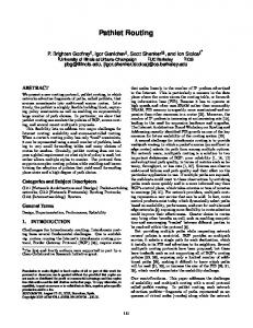
2.2 NP Hardness To prove the NP-hardness of the energy-aware routing problem, we translate ERP-1 into an equivalent problem: ERP-2. ERP-2: Given there is a tuple of input parameters of (G, T, K, N), G, T, K denote topology, traffic matrix and predefined threshold respectively, which are the same as ERP-1. N is a threshold number. The object of ERP2 is to find a routing R2, satisfying the two conditions as follows: 2 (3) 2 (4) where the functions of L(.) and M(.) are the same as those in ERP-1. The translation from ERP-1 to ERP-2 is shown in the following pseudocode. ERP-1(G, T, K) begin set N := the number of all switches in the network; While (the solution of ERP-2(G, T, K, N) exists) begin set result := ERP-2 (G, T, K, N); set N := N-1; end return result; end
2. ENERGY-AWARE ROUTING MODEL
Figure 1: Translation from ERP1 to ERP2
In this section, we first formally establish the model of energy-aware routing problem. Then, we prove that it is an NP-Hard problem by reducing from 0-1 Knapsack problem into the energy-aware routing problem.
From above it is clear that the solution of ERP-1 can be got by solving ERP-2 repeatedly, for at most N steps. Therefore, the hardness of ERP-1 is not harder than ERP2, ERP-2. On the other hand, obviously, ERPi.e. ERP-1 2 ERP-1. Thus the hardness of ERP-1 and ERP-2 are equivalent. ERP-1 is NP-hard if and only if ERP-2 is NPhard. Next, we present the proof of the NP-hardness of ERP-2. Our idea is to reduce the classical 0-1 Knapsack problem into the ERP-2 problem. 0-1 Knapsack problem belongs to the well known Karp's 21 NP-complete problems [9]. The definition of 0-1 Knapsack problem is as follows [10]. There are n kinds of items denoted by , , … , , and , ,…, . Each kind of item j has a let weight and a value . It is assumed that all weights and values are nonnegative. The maximum weight can be carried in the bag is C, and E is defined as the predefined threshold of the total value of items, where C and E are both nonnegative values. The number of copies of each kind of item is restricted to zero or one. The object of 0-1 Knapsack problem is to find a subset of items (equivalent to assigning value to each ), subjecting to the following two conditions: ∑ (5) ∑ , 0,1 (6)
2.1 Model Description The object of energy-aware routing is to compute the routing for a given traffic matrix, so that as few switches are involved as possible to meet a predefined performance threshold. Throughout this paper we use network throughput as the performance metric, since it is the most important metric for data-intensive computations. We can modelize the energy-aware routing problem as ERP-1. ERP-1: Assume there is a tuple of input parameters, (G, T, K). G denotes the topology of data center network, containing all servers and switches, and the connection relationships and network capacity among them. T denotes the traffic matrix upon all servers, in which 1 indicates there is a flow between two servers, while 0 means no such flow. K denotes the predefined threshold of network throughput. The object of energy-aware routing is to find a routing R1 for T, which subjects to the following two conditions: (1) 1 Min , 1 (2) is the space of all possible routings for T, L(R1) where denotes the number of switches involved in R1, and M(R1) is the network throughput of T under R1.
2
Figure 2: topology and traffic construction in the instance of ERP-2 Tht . into two subsets: 1 and 2, subject to 1 2 1 2 . 1 and 2 are defined by , ,1 1 2 1. Therefore, we can see that Tht 2 0, as the nodes in 2 are not able to form a complete path for any flow, and Tht 1 2 1 Tht Tht Tht . On the other hand, | 1| | | , as 1 is the subset of . Therefore we can find the subset of items , such that ∑ | 1| ∑ Tht 1 . Consequently, the solution of 0-1 Knapsack problem exists. End. Based on the three-step proof above, we conclude that ERP-2 is an NP-hard problem, thus ERP-1 is also NP-hard.
The 0-1 Knapsack problem can be reduced to ERP-2 problem in polynomial time, which consists of three steps as follows. Step 1: Instance Construction We first construct a specific topology G in ERP-2. The set of all nodes in G is divided into n groups. Each group j 1 links, as shown in Figure 2. contains nodes and The network capacity of each link in group j is . Then we construct n flows: flow 1, flow 2, …, flow n. The source node of flow j is the first node in group j, and the destination is the last node in group j. Let be the set of nodes in the path of flow j, and , ,…, . Therefore, the number of nodes in is equal to and the throughput of flow j is equal to . Finally, we let the predefined threshold N be equal to C, and let the predefined threshold K be equal to E. Step 2: if the solution of 0-1 Knapsack problem exists, then the solution of the ERP-2 instance also exists. Proof: If the solution of 0-1 Knapsack problem exists, i.e., , such that ∑ ∑ ,1 . Then , such that ∑ ∑ ,1 . Therefore, there exists a specific routing for n flows, so that the number of nodes involved in the routing is not more than N, and the total throughput is not less than K. Consequently, the solution of the ERP-2 instance exists. End. Step 3: if the solution of the ERP-2 instance exists, then the solution of 0-1 Knapsack problem also exists. Proof: If the solution of the ERP-2 instance exists, i.e., there exists a specific routing for n flows, so that the number of nodes involved in the routing is not more than N, and the total throughput is not less than K. Let denote the set of nodes involved in the routing, let the function Tht denote the total throughput of the flows only traversing the nodes in , and let | | denote the number of nodes in . Then | |
We divide
3. HEURISTIC ROUTING ALGORITHM In this section, we propose a heuristic routing algorithm for an arbitrary DCN topology. We make a simple assumption that TCP traffic is dominant in data centers and networking is the bottleneck for data-intensive applications, so the flows are regarded as elastic flows [11]. Moreover, to avoid packet disorder, we use connection-unsplittable routing, i.e., the packets from one flow takes only one path. The object of our heuristic routing algorithm is to compute the routing for all flows in traffic matrix, so that as few switches as possible are involved in the routing to meet a predefined performance threshold. The basic idea of the algorithm is as follows. First, taking all switches into consideration, we compute the routing and the corresponding network throughput which are called basic routing and basic throughput respectively. Second, we gradually eliminate the switches from those involved in basic routing, based on the specific elimination order depending on the workload of switches. When the network throughput decreases to the threshold we can tolerate, we finish the elimination process and obtain the energy-aware
3
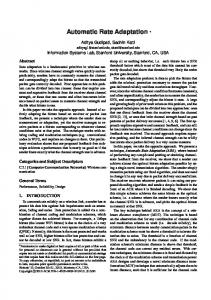
routing. Finally, we power off the switches not involved in the energy-aware routing, or put them into sleep mode. Our heuristic routing algorithm consists of three modules: Route Generation (RG), Throughput Computation (TC), and Switch Elimination (SE). The relationship among the three modules is shown in Figure 3. Figure 4 shows the pseudocode of our heuristic routing algorithm (HRA). The input of the algorithm is the tuple (G0, T, PR). G0 denotes the data center network topology, T denotes the traffic matrix upon all servers, and PR is performance threshold percentage, which is defined as the network throughput we can tolerate over the basic throughput using all switches. Here, we translate the parameter K in the energy-aware routing model into PR for legibly measuring performance decrement resulting from energy-aware routing. In fact, the parameter K is equal to PR multiplies by the basic throughput. The output of the algorithm is the tuple (R, G). R denotes the energy-aware routing we choose for T, and G denotes the topology not containing the switches eliminated by SE().
characteristic of data center networks to accelerate the pathselection process. HRA(G0, T, PR) Notations: G0: DCN topology T: traffic matrix PR: performance threshold percentage begin 1 set G := G0; 2 //Route Generation 3
set R := RG(G, T);
4
//Throughput Computation
5
set Tht1:= TC(G, T, R);
6
do
7
begin
8
//eliminate the switches carrying the lightest traffic
9
set G := SE(G, T, R);
10
set R := RG(G, T);
11
set Tht2:= TC(G, T, R);
12
set P := Tht2 / Tht1;
13 end while(P>=PR ) 14 return (R, G);
End
Figure 3: Components of our algorithm
Figure 4: Heuristic routing algorithm
In Figure 4, we generate the basic routing R for T in topology G0 shown in line 3, and compute the basic throughput with the basic routing R in topology G0 shown in line 5. From line 6 to line 13, we execute three modules repeatedly until P is less than PR, where P is the ratio of the throughput in G to the basic throughput in G0. In each round, we first eliminate some switches and associated links from G (the eliminating rule will be explained later) shown in line 9. Then, we generate the routing for T in the updated topology G, and compute the corresponding throughput shown in line 10 and 11. Route Generation: The role of the route generation module is to select the routing for each flow in traffic matrix so that the network throughput is as high as possible. Each selected path can be computed with the inputs (G, T), and the output of RG() is the routing paths for all flows in traffic matrix in topology G. For simplicity, we assume the capacity of links in topology is the same. We compute the paths by incrementally adding flows into the network. For a certain flow, the ideal solution is to enumerate all possible paths for a flow. However, it may not be practical for large-scale networks. Hence, there is a tradeoff between the computation complexity and the efficiency of the results. Moreover, we can take advantage of topological
Assume there are a certain number of possible paths for a flow. We first select the path with the fewest overlapping flows over the bottleneck link in the path. If there are multiple such paths, the one with the shortest hops is chosen. Throughput Computation: The module of throughput computation is to calculate the network throughput in a given topology. We use the Max-Min Fairness model [12] to sum up the throughputs of all flows. The computational , where LN denotes the complexity of TC() is Ο number of links in topology. Switch Elimination: The switch elimination module is responsible for selecting the switches which can be eliminated from the routing for the traffic matrix. We use a greedy algorithm for the elimination process. First, we compute the traffic carried by each active switch in topology G, which is the total throughput of flows traversing the switch. Then, we select the active switches carrying the lightest traffic. And these switches can be put into sleep mode or be shutdown. To accelerate the computation process, we may eliminate more than one switch from G per round. Another thing to note is that the switches eliminated from G cannot be the critical ones, i.e., the topology will be partitioned without them.
4
P e r c e n t a g e o f E n e r g y S a v e d o n S w it c h e s ( % )
P e r c e n ta g e o f E n e r g y S a v e d o n S w it c h e s (% )
100
60
BN=4,BL=2 BN=8,BL=2 BN=8,BL=3
80
flow=500 flow=1000 flow=5000 flow=10000
50 40
60
30
40
20
20
10
01 10
10
2
10
3
10
4
10
5
0 60
65
70
The Number of Flows
80
85
90
95
100
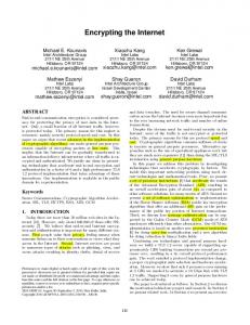
(b) Figure 5: Energy saved by our algorithm in BCube
100
P e r c e n ta g e o f E n e r g y S a v e d o n S w itc h e s (% )
P e r c e n ta g e o f E n e r g y S a v e d o n S w itc h e s (% )
(a)
75
Performance Threshold Percentage (%)
60
FP=12 FP=24 FP=48
80
flow=500 flow=1000 flow=5000 flow=10000
50 40
60
30
40
20
20 01 10
10
10
2
10
3
10
4
10
5
The Number of Flows
(a)
0 60
65
70
75
80
85
90
95
100
Performance Threshold Percentage (%)
(b) Figure 6: Energy saved by our algorithm in Fat-Tree are saved; and the figure increases to 80% if the number of flows is less than 100. As expected, the energy-saving effectiveness decreases as the network load increases. In Figure 5(b), we consider a certain BCube topology, i.e., a BCube(8,3), but vary performance threshold percentage. Not surprisingly, as the performance threshold percentage increases, the energy-saving effect decreases, because higher performance requirement indicates less opportunities to eliminate switches. Hence, there is a tradeoff to be made by data owners according to real circumstances. Note that we can also save much energy even without any performance sacrifice, i.e., the performance threshold percentage is 100%, when the network load is low. Figure 6 shows the simulation results in Fat-Tree. In Figure 6(a), we also set performance threshold percentage as 95%. The curves show that our algorithm can also save considerable energy consumed by switches at low load in Fat-Tree. In Figure 6(b), we conduct the simulation in a certain Fat-Tree topology, i.e., FP is 24. Similar to Bcube, the effect of energy saving decreases as the performance threshold percentage increases.
4. EVALUATION In this section, we evaluate our energy-aware routing algorithm by simulation in BCube and Fat-Tree, both of which are typical topologies for data center network.
4.1 Simulation Setup For BCube(BN, BL) topology, where BN denotes the number of ports in a switch and BL denotes the number of levels, we set different values of BN and BL to vary the topology scales. Similarly, we vary the number of ports in switch in Fat-Tree, denoted as FP. We assume the network capacity of all links in these topologies is 1Gbps. We change the number of flows in a topology to simulate different network load, and the traffic matrix is randomly generated upon servers.
4.2 Results Our simulation results in BCube are shown in Figure 5. In Figure 5(a), we set performance threshold percentage as 95%, and evaluate the effect of energy saving on switches with increasing network load for different topology scales in BCube. The curves show that our energy-aware routing algorithm significantly saves energy consumed by switches at low network load. For example, in BCube(8,3), when the number of flows is less than 1000, more than 20% energy
5. RELATED WORK Data Center Network: Due to the well-known problem of the current practice of tree topology, recently there are a
5
bunch of proposals on new topologies for data centers. These topologies can be divided into two categories. One is switch-center topology, i.e., putting interconnection and routing intelligence on switches, such as Fat-Tree [4], Portland [13], and VL2 [14]. Contrarily, the other category is server-centric, namely, servers, with multiple NIC ports, also participate in interconnection and routing. DCell [6], BCube [5] and FiConn [15], all fall into the latter category. Green Internet: The problem of saving overall energy in the Internet was firstly proposed by Gupta et al. in a position paper [16]. Later, they explored the feasibility in local area network [17], and proposed useful techniques to put idle components in network devices into sleep. In follow-on work, lots of efforts focused on device power management [18] [19], realizing two modes: sleeping and rate-adaptation on network devices to reduce energy consumption during network idle or low-load times. Moreover, Wisconsin-Madison University and Cisco Systems advocated a broad approach including regarding power-awareness as a primary objective in the design and configuration of networks and protocols, and using mixed integer optimization techniques to optimize the energy consumption of network devices [20]. Green Data Center: There were also more and more concerns with energy saving in data center network. New low-power hardware [21] [22] [23] and smart cooling technologies [24] were effective methods to save energy. Intel Research proposed and evaluated the proxy architecture which used a minimal set of servers to support different forms of idle-time behavior for saving energy [25]. The similar idea was proposed in [26], which believed that consolidation of applications in cloud computing environments could present a significant opportunity for energy optimization. In a recent work, Heller et al proposed a network-wide power manager named ElasticTree [7] to extend the idea of power proportionality into the network domain, as first described by Barroso et al [27].
8. REFERENCES [1] S. Ghemawat, H. Gobioff, and S. Leung. The Google
File System. In SOSP, 2003. [2] CloudStore. Higher Performance Scalable Storage.
http://kosmosfs.sourceforge.net/. [3] J. Dean and S. Ghemawat. MapReduce: Simplified
Data Processing on Large Clusters. In OSDI, 2004. [4] M. Al-Fares, A. Loukissas, and A. Vahdat. A Scalable,
Commodity Data Center Network Architecture. In SIGCOMM, 2008. [5] C. Guo, G. Lu, D. Li, H. Wu, X. Zhang, Y. Shi, C.
Tian, Y. Zhang, and S. Lu. BCube: A High Performance, Server-centric Network Architecture for Modular Data Centers. In ACM SIGCOMM, August 2009. [6] C. Guo, H. Wu, K. Tan, L. Shi, Y. Zhang, and S. Lu.
DCell: A Scalable and Fault-Tolerant Network Structure for Data Centers. In ACM SIGCOMM, pages 75–86, 2008. [7] B. Heller, S. Seetharaman, P. Mahadevan. ElasticTree:
Saving Energy in Data Center Networks. In NSDI’10, Apr 2010. [8] U.S. Environmental Protection Agency. Data Center
Report to Congress. http://www.energystar.gov. [9] R.M.Karp. Reducibility Among Combinatorial
Problems, in R.E.Miller and J.W. Thatcher (Eds.), Complexity of Computer Computations. Plenum Press, New York, 1972. [10] A.Levitin. Introduction to the design & analysis of
algorithms. Addison-Wesley, 2003. [11] D.Nace, N.L.Doan, E.Gourdin, B.Liau. Computing
Optimal Max-Min Fair Resource Allocation for Elastic Flows. IEEE/ACM Transactions on Networking 16(6): 1272-1281, 2006.
6. CONCLUSION
[12] D.Bertsekas, R.Gallager. Data networks. Englewood
In this paper, we solve the energy-saving problem in data center networks from a routing perspective. We first formally established the model of energy-aware routing, and proved that it is NP-hard by reducing 0-1 Knapsack problem into it. Then, we proposed a heuristic algorithm to solve the energy-aware routing problem. Simulation results showed that our algorithm is effective in energy saving on network devices in data centers, especially when the network load is not high. The work presented in this paper is preliminary, but shows that energy-aware routing in DCN is promising. We are also developing the prototype systems. In the future, we hope to extend energy-aware routing to more general application contexts, e.g., delay-sensitive applications.
Cliffs, NJ: Prentice-Hall, 1992. [13] R. N. Mysore, et al. PortLand: A Scalable Fault-
Tolerant Layer 2 Data Center Network Fabric. In ACM SIGCOMM, August 2009. [14] A. Greenberg, N. Jain, S. Kandula, C. Kim, P. Lahiri,
D. Maltz, P. Patel, and S. Sengupta. VL2: A Scalable and Flexible Data Center Network. In ACM SIGCOMM, August 2009. [15] D. Li, C. X. Guo, H. T. Wu, K Tan, Y. G. Zhang, S. W.
Lu. FiConn: Using Backup Port for Server Interconnection in Data Centers. In INFOCOM 2009. [16] M. Gupta, S. Singh. Greening of the Internet. In ACM
SIGCOMM, Karlsruhe, Germany. August 2003.
7. Acknowledgment
[17] M. Gupta and S. Singh. Using Low-Power Modes for
This work was supported by HI-Tech Research and Development Program of China (863) under Grants 2007AA01Z2A2.
Energy Conservation in Ethernet LANs. INFOCOM’07, May 2007.
6
[18] S. Nedevschi et al. Reducing network energy
[23] G. Ananthanarayanan and R. H. Katz. Greening the
consumption via sleeping and rate-adaptation. In Proceedings of the 5th USENIX NSDI, pages 323– 336, 2008.
Switch. HotPower’08, Dec 2008. [24] C. Patel, C. Bash, R. Sharma, M. Beitelmam, and R.
Friedrich. Smart Cooling of data Centers. In Proceedings of InterPack, July 2003.
[19] K. Christensen, B.Nordman, R.Brown. Power
Management in Networked Devices. In IEEE COMPUTER SOCIETY, August 2004.
[25] S. Nedevschi, J. Chandrashekar, and B. Nordman.
Skilled in the Art of Being Idle: Reducing Energy Waste in Networked Systems. NSDI’09, Apr 2009.
[20] J. Chabarek, J. Sommers, P. Barford, et al. Power
Awareness in Network Design and Routing. INFOCOM’08, Apr 2008.
[26] S. Srikantaiah, A. Kansal and F. Zhao. Energy Aware
Consolidation for Cloud Computing. HotPower’08, Dec 2008.
[21] G. Magklis, M. Scott, G. Semeraro, and etc. Profile-
based Dynamic Voltage and Frequency Scaling for a Multiple Clock Domain Microprocessor. In ISCA’03, Jun 2003.
[27] L. A. Barroso, U. Hlzle. The case for energy-
proportional computing. Computer, 40(12):33– 37,2007.
[22] D. Meisner, B. Gold, T. Wenisch. PowerNap:
Eliminating Server Idle Power. In ASPLOS’09, May 2009.
7