Ensemble Routing For Datacenter Networks Mike Schlansker, Yoshio Turner, Jean Tourrilhes, Alan Karp HP Laboratories HPL-2010-120 Keyword(s): Networks, Ethernet, Multipath, Switching, Fault Tolerance
Abstract: This paper describes Hash-Based Routing (HBR), an architecture that enhances Ethernet to support dynamic management for multipath networks in scalable datacenters. This work enhances HBR to support flow ensemble management for large-scale networks of arbitrary topology. Ensemble routing eliminates measurement and control for individual flows and instead manages using summary data thus providing a unique capability for reactive datacenter-wide network management. HBR provides seamless interoperability with Ethernet and supports the attachment of unmodified L2 hosts and devices including FCoE devices within converged fabrics. Simulation experiments demonstrate efficient multipath routing for a variety of scalable topologies. Optimized routing maintains efficiency in the presence of network faults and implements spatial Quality of Service to dynamically provision physical network hardware among co-hosted tenants or applications.
External Posting Date: September 21, 2010 [Fulltext] Internal Posting Date: September 21, 2010 [Fulltext] To be presented at ANCS, San Diego, CA
Copyright ANCS, 2010
Approved for External Publication
Ensemble Routing For Datacenter Networks Mike Schlansker
Yoshio Turner
Jean Tourrilhes
Alan Karp
[email protected]
[email protected]
[email protected]
[email protected]
Hewlett-Packard Laboratories ABSTRACT This paper describes Hash-Based Routing (HBR), an architecture that enhances Ethernet to support dynamic management for multipath networks in scalable datacenters. This work enhances HBR to support flow ensemble management for large-scale networks of arbitrary topology. Ensemble routing eliminates measurement and control for individual flows and instead manages using summary data thus providing a unique capability for reactive datacenter-wide network management. HBR provides seamless interoperability with Ethernet and supports the attachment of unmodified L2 hosts and devices including FCoE devices within converged fabrics. Simulation experiments demonstrate efficient multipath routing for a variety of scalable topologies. Optimized routing maintains efficiency in the presence of network faults and implements spatial Quality of Service to dynamically provision physical network hardware among co-hosted tenants or applications.
Categories and Subject Descriptors C.2.1 Network Architecture and Design
General Terms Design, Management, Performance, Reliability
Keywords Networks, Ethernet, Multipath, Switching, Fault Tolerance
1. INTRODUCTION This paper enhances Hash Based Routing (HBR) for datacenter networks [1]. HBR supports cost-effective and scalable L2 networks with multipath routing for high bisection bandwidth. While HBR was originally limited to fat tree topologies, this paper contributes enhancements including an architecture for the static and dynamic management of arbitrary topology L2 Ethernet networks, and experimental results that demonstrate the utility of the architecture for scalable fault tolerant networks and Quality of Service applications. Enhancements to static management analyze irregular traffic and irregular network topologies to identify oblivious management policies (like Valiant routing [2]) that optimize multipath flow for irregular traffic on arbitrary unstructured networks. Dynamic management adds major qualitative advantages when compared to using overprovisioned hardware with static management. Dynamic
management layered on top of HBR provides unique capabilities in areas of fault tolerance, online maintenance, Quality of Service, and power. HBR is a pure network architecture requiring no host or end-device modifications. HBR differs from other multipath approaches in that it closely follows and builds on layer-two Ethernet’s base architecture while enabling adaptive and scalable datacenter-wide routing. The architecture provides a fully compatible L2 Ethernet network. Legacy Ethernet switches can be attached at the edge of the fabric, and L2 host, LAN, and FCoE devices can be attached to those switches without special registration. Device mobility is supported as in normal L2 networks where an L2 timeout or gratuitous L2 broadcast is sufficient to clear stale Ethernet learning cache data. Unlike L2 switching, Layer 3 routing exploits IP addresses structure in harmony with controlled device placement. For example, routing is simplified when devices in one customer’s IP range are on the right side of a datacenter while devices in another customer’s range are on the left. For modern datacenters, however, devices are often virtualized and dynamically provisioned. Device location is not easily controlled and may change frequently. This defeats the utility of routing using compressed L3 wildcard or range TCAM rules. Since L3 addresses have no geographic use, HBR uses L2 addresses to improve compatibility. L2 addresses are unstructured and not useful in compressed range or wildcard rules. Thus, for approaches such as OpenFlow [3] that rely on existing TCAMs, compressed rules cannot be used and at least one rule (often more) is needed for each addressable device, representing a serious problem for large datacenters having many virtual devices. In this case, the number of allowed virtual devices depends on the number of physical TCAM entries in a switch. The HBR architecture is based on two key principles. The first principle asserts that centralized out-of-switch software provides important advantages over distributed in-switch protocols. This approach follows that of InfiniBand’s subnet manager [4]. Subnet manager software, assisted by components in every switch, allows flexible and powerful datacenter-wide control. The subnet manager simplifies the deployment of new datacenter-wide management capabilities. Switch hardware remains simple, and complex control is performed by external soft-
ware. New capabilities evolve by enhancing subnet manager software without complex switch firmware/hardware upgrades and without waiting for new industry standard distributed protocols that may not provide needed datacenter management solutions. The second principle asserts that managing individual flows or managing traffic to individual destination devices is too fine grained. Some approaches manage individual flows without adequately addressing the needs of datacenters that may include thousands of L2 devices each supporting many small and transient flows. Architectures that maintain and update per-flow management state will be expensive to implement, and unable to quickly react to changing traffic and changing hardware. Architectures are needed that dynamically manage large ensembles of transient and hard to predict flows between end-stations that may be virtualized and may move with host migration. HBR manages traffic at the granularity of an ensemble. Thus, with HBR the size of the management state is independent of the number of flows or destination addresses. Ensemble routing is defined in a two-tiered hierarchy. Injected packets first encounter a routing layer, which routes each flow ensemble onto one of multiple routing networks providing path diversity. A switching layer uses conventional Ethernet switching within the routing networks to direct individual packets to their destinations. Routing for flow ensembles is different from conventional switching or routing because each ensemble identifies flows having diverse sources and destinations, and routing must accommodate this diversity. The lower level switching layer, used to forward packets in each routing network, exploits existing Ethernet learning and efficiently detects forwarding ports for destination addresses. Per-destination switching information is cached and can be dropped and re-learned efficiently using traditional learning functions. A primary advantage of ensemble routing is that only a small amount of routing state is needed to control network traffic throughout a large datacenter. This facilitates fast reactive management of huge numbers of flows with simpler control than is possible for per-flow management. Both subnet manager software and the switch hardware are simplified. The manager gathers and processes condensed information to determine optimized control settings. A terse list of control settings is sent back to switches to maintain correct and efficient operation. Switch hardware maintains a small management state. A disadvantage of ensemble routing is that it sacrifices fine grained control for individual flows. This may cause some flows to take non-optimal paths. Our experimental results indicate that for large datacenter networks, the scalable control advantages of ensemble routing outweigh the disadvantages.
2. Hash Based Routing Architecture Previous work [1] on HBR minimized routing state by managing flow ensembles. Packets within a flow are mapped to the same ensemble so that each flow is carried on a single path that preserves packet order. Pseudorandom hashes identify ensembles, which are mapped to physical switch ports to optimize multipath routing in fat trees. Symmetric flow identification ensures that bidirectional communications take congruent outbound and reply paths preserving Ethernet learning efficiency. Asymmetric HBR is also of interest but not treated here. This paper presents hardware architectural enhancements to HBR and new software management algorithms to manage arbitrary traffic ensembles within arbitrary network topologies. Enhancements shown here identify flow ensembles called routing classes that contain hash and priority information for multipath and QoS. Routing classes now are mapped onto routing VLANs to control traffic in complex topologies. Routing classes are derived from packet headers. Specifically, each flow has an associated traffic class and a hash class. The traffic class identifies customers, applications, or traffic types (e.g. LAN vs storage) to allow differentiated traffic treatment for QoS. Flows in a single traffic class receive equal fair treatment. The hash class supports path diversity within each traffic class and identifies an ensemble of flows that have the same hash value and follow the same route. The routing class is the smallest unit for traffic measurement and control. Routing classes are identified with a routing class id that is formed by concatenating traffic and hash class identifiers. The granularity or the number of hash classes that subdivide each traffic class can be adjusted by choosing the number of hash output bits that are included in the routing class specification. HBR uses routing VLANs to navigate networks with arbitrary topology. An enhanced HBR switch, first described here, is placed at all ingresses to a core multipath network. The switch performs a programmable lookup to direct routing classes to VLANs. Routing VLANs draw on prior research [5-7] and exploit existing switch capabilities while preserving customer-visible VLANs at the fabric edge (e.g. using VLAN stacking). Routing VLANs are carefully constructed for efficient ensemble routing. An HBR edge switch encapsulates packets in a routing VLAN. Packets are conventionally forwarded (within the routing VLAN) through the network core, and packets are decapsulated at the egress. VLAN encapsulation hides routing VLANs from all network devices. HBR efficiency is demonstrated below for multiple network topologies.
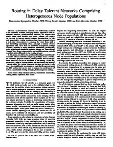
2.1 Routing for Fat trees Figure 1 shows a folded Clos or fat tree network [8]. Fat trees offer many equal length paths between edge switches and simplify multipath control. Edge uplinks are color coded with the top switch to which they connect. A routing VLAN is defined for each top switch with its cor-
responding color. Uplinks can be augmented with parallel links (as Link Aggregation Groups or LAGs) to provide additional bisection bandwidth.
Figure 1: Fat Tree Active load balancing maps routing classes to carefully selected VLANs to manage the upward flow of packets. A central manager (not shown) continuously measures traffic load. The manager implements a datacenter-wide policy, by setting values in ensemble routing tables within each switch to control the distribution of traffic across VLANs and top switches.
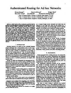
Figure 2: Fat Tree with Faults An example that demonstrates flexible management for complex and changing network topologies is shown in Figure 2 where two failed links are marked with an X. Consider the failed uplink on the E3 edge switch. Traffic that exits E3 cannot be routed through port 3. Routing VLANs are reprogrammed in reaction to topological changes like link failures. An alternative bypass path is provided within the reprogrammed VLAN that starts at the port 2 uplink, enters the T2 top switch and passes through the E2 edge switch and back to the T3 top switch. This dark solid red VLAN provides an acyclic network and fully flexible communications between downlinks.
2.2 Routing for Cliques Figure 3 shows an example meshing fabric arranged in a clique topology that eliminates unnecessary switches and hops from fat trees. This example uses 6 links to directly connect 4 switches. Each physical link is shown as a pair of colored (dashed) lines. Separate colors indicate routing VLANs that are carried on each link. Each VLAN reaches all switches. Direct connect topologies are more complex to manage as controllers balance competing objectives for sending traffic on a shortest path and spreading traffic across multiple non-optimal paths. However, these networks efficiently scale to large configurations with future high port count switches.
2.3 Routing for HyperX Prior work has shown that multidimensional clique networks called HyperX [9] efficiently scale. While harder to control than fat trees, these networks use fewer components and smaller hop counts. A 44 HyperX network is shown in Figure 4. Each row is connected as a clique (like Fig. 3) to row members and each column is connected as a clique to column members. Each HBR switch provides six uplinks. Forty eight uplinks (6 in each oval clique) connect 9 switches. Example routing VLANs are not illustrated but are constructed using simple algorithms (Section 4.2) that facilitate experiments below.
2.4 Broadcast and Control Traffic A network is needed to control switches. A control VLAN is constructed as a conventional spanning tree that reaches all Ethernet switches and devices. This network supports control actions such as programming VLANs. Broadcasts can disrupt system performance when hosts must process and dismiss too many broadcast packets such as ARPs needed to discover unknown IP-to-MAC address bindings. Similar L2 Flooding occurs when switches have no learning entry for a destination. As with normal Ethernet, HBR broadcast and flood packets are encapsulated within a routing VLAN and decapsulated from that VLAN like any other packet. While such broadcasts do propagate through the high bandwidth network core, at the edge of the fabric, the broadcast scope is contained within tenant- or application-oriented VLANs. We preserve conventional L2 behavior which limits the scope of broadcasts to edge devices within appropriate VLANs.
3. HBR Switch Architecture Figure 3: Clique
Figure 4: HyperX
An example bypass path has also been constructed to accommodate a failed link between T0 and E0. This illustrates that the network architecture can accommodate multiple link failures. The management changes needed to handle faults – setting up new routing VLANs and new routing class assignments to routing VLANs – are independent of both flows and destination addresses.
The HBR switch in Figure 5 is logically divided into four layers that separate downlinks from uplinks. Downlinks connect to standard Ethernet devices including hosts, storage, and switches. Uplinks interconnect HBR switches in a multipath routing fabric and carry packets that are encapsulated in routing VLANs. The edge layer is a conventional Ethernet network that connects downlinks to the core. The core is also a conventional Ethernet network that interconnects HBR switches and may include conventional (non HBR) switches such as the fat-tree top
switches. The core layer uses routing VLANs to direct multipath traffic through complex network topologies. Some packets traverse the edge layer from downlink to downlink as a conventional Ethernet switch. Other packets are destined for uplinks that traverse the core and participate in managed multipath routing. Uplink-bound packets traverse traffic classification and routing layers through a special virtual “Uport” that carries packets that are destined for the core. The traffic classification layer maps up-bound packets into classes that receive similar QoS treatment in the core. The hash-based routing layer distributes up-bound packets into hash classes that support multipath load balancing. Traffic class and hash class information are combined to identify individual routing classes. Routing classes are dynamically mapped to routing VLANs to support active management. The virtual “Dport” carries downward-bound packets destined for the edge. These packets are decapsulated from the routing VLAN and then processed by conventional edge layer switches. The HBR switch combines core and edge switch functions into a single switch. As a result, the switch performs up to two learning actions on a single packet. Each learning action requires the two traditional components: using the source address to learn new cache entries, and using the destination address to reference previous entries that identify destination ports.
routing VLAN. The switch selects a routing VLAN for the packet by performing traffic classification, hashing, and the routing VLAN lookup. The packet is then encapsulated in the chosen routing VLAN. A source address substitution (for learning only) indicates to subsequent egress learning that the packet was seen arriving into the routing domain from the Dport. Alternatively, the result of the ingress learning lookup may be the Dport, indicating that a packet is down-bound and exiting a routing VLAN. The packet is decapsulated from the routing VLAN. A source port substitution indicates to subsequent egress learning that the packet was seen arriving from the routing domain on the Uport. For packets that enter or exit the routing domain, a second egress learning lookup identifies the egress port within the resulting VLAN after the domain change. After this second lookup, normal switch processing resumes, and the egress port id is used to send the packet across the switch’s internal data path to the appropriate port. Packets that enter the routing domain emerge from the ingress learning lookup with the “Uport” as the virtual destination. For these packets, a route lookup is performed and the packet is encapsulated in the selected routing VLAN. After routing, the packet is again processed by the egress learning lookup.
3.2 Traffic classification At the edge of the routing fabric, incoming packets are classified into traffic classes. Traffic classes are flow ensembles that receive independent management treatment. Packets within a single traffic class share identical QoS goals across the fabric. Traffic classification inputs include the Ethertype, the customer VLAN, and (if the Ethertype type is IP) the protocol field. The traffic classification process interfaces high-level service class objectives with low-level features that are defined by the Converged Enhanced Ethernet specification. CEE defines priority and class of service fields that specify differential packet treatment and lossy versus lossless flow.
3.3 Hashing
Fig. 5: HBR Switch
Fig. 6: Header Processing
3.1 Packet processing flow The switch flow diagram for packet header processing is shown in Figure 6. An ingress learning lookup performs ingress-side switching. The ingress may be on either the core-side or on the edge-side. The lookup result is an egress port that can be a normal port or a special virtual destination port (Uport or Dport). Packets directed to normal ports traverse the switch as a conventional switch (core or edge), without crossing the routing layer. If the ingress learning lookup result is the Uport, it indicates that the packet is up-bound and should enter a
Hash classes are identified by applying a hash function to packet header fields. The function is repeatable and the re-application of any input produces an identical result. For each source address s and each destination address d, H(s, d) represents the hash class for every message sent from s to d. This hash may incorporate L2 or higher layer information. Each ordered stream is mapped to a single hash class so that the stream traverses a unique path. Symmetric hashes have H(s, d) = H(d, s). Symmetric hashes ensure that after a message traverses from a source to a destination, the same path is retraced by a reply. Symmetric or congruent routes simplify Ethernet learning needed to eliminate flooding and help to preserve Ethernet’s plug-and-play properties.
This section describes a hash implementation which is based on exclusive or logic and is used for our experiments (Section 6). The hash input is formed using fields from the packet header. A hash function “out=H(input)” is then used to pseudo-randomly distribute input values to output values. A matrix approach based on bitwise XOR and logical AND is used. Assume that a hash function H is applied to S input bits in input vector IN to produce R result bits for output vector OUT. Consider a Boolean coefficient matrix C having R rows and S columns. We implement H using the matrix product OUT = CIN which is rewritten as: OUTij= 0jS CijINj for each i, 0iR. Here, the product is a simple Boolean AND. The summation is the exclusive or of all product bits. This hash is easily computed with modest hardware.
3.4 Routing VLAN Lookup The routing lookup enforces fabric-wide management decisions. The lookup can be implemented using TCAMs in each switch that are set by a subnet manager to control packet flow across the fabric. The lookup key consists of the packet’s traffic and hash classes. A match isolates a single routing class and produces a VLAN tag result that specifies the selected routing VLAN for that routing class. The number of TCAM entries needed for HBR routing is estimated as the number of routing classes which is equal to the number of traffic classes times the number of hash classes in each traffic class. For example 1024 TCAM entries could be used to manage sixteen distinct traffic classes in fractional traffic increments of 1 part in 64. TCAM hardware allows substantial management flexibility, and traffic classes need not be managed with equal granularity.
4. Network Management Architecture Our traffic management architecture has two layers. A slowly reactive topology planning layer defines logical Ethernet networks. Topology planning reacts only to changes in the network topology such as link failures. Topology planning is implemented using network discovery, which characterizes the current physical fabric, and routing VLAN construction, which identifies optimized routing networks for traffic management. A more highly reactive dynamic management layer assigns flow ensembles to routing VLANs. Dynamic management reacts to changes in traffic patterns or QoS goals. Dynamic management is implemented using traffic projection, which predicts the impact of proposed traffic changes based on previous traffic measurements, and route optimization, which provides heuristics that identify optimized routes for all traffic. Dynamic datacenter-wide active management is implemented using a subnet manager. Our current subnet manager is a central controller that sends and receives simple commands to observe and control switches. The switches interpret control messages and perform low-level man-
agement actions. The subnet manager executes a management cycle loop that collects per-hash-class data from each switch, computes an optimized fabric-wide management policy and downloads management instructions to all switches. The centralized manager may appear to impose a performance bottleneck for reactive management action. However, due to efficiencies that result from the use of summary per-routing-class data, experiments [10] have shown that centralized management can provide between 10 and 100 datacenter-wide management operations per second without undue communication or computation needs. Distributed subnet managers are also of interest but have not yet been designed. Many routing architectures use oblivious (e.g. Valiant) routing to support multipath. Not only does this work extend oblivious routing to non-uniform traffic and topologies, we dynamically exploit slow time varying changes in traffic that arise from the provisioning of new customers or the initiation of new applications. We show that exploiting such non-uniformities enhances efficiency.
4.1 Network Discovery Networks may have regular or irregular topology and must accommodate switch and link failures that occur within large scale datacenters. Network discovery lays the physical foundation for topology planning. As components are brought on-line or taken off-line or fail, network discovery provides an up-to-date physical map of available switches and their connectivity.
4.2 Routing VLAN Construction Routing VLAN construction identifies a current set of routing VLANs used to manage traffic across the discovered topology. Routing VLANs support multipath load balancing, and traffic isolation or differential traffic service. Each routing VLAN reaches every edge switch and is capable of transporting packets to any destination. VLAN construction builds each routing VLAN from a seed that identifies a root switch. A VLAN is grown as a tree where each switch is reached by a shortest path from the seed. The algorithm progressively identifies neighbor switches with increasing radius from the root. Hop-count ties are broken by favoring links that host fewer VLANs, and using bisection bandwidth heuristics. After a VLAN is constructed, a use count is incremented on links that are traversed by the VLAN to discourage growth of new VLANs across previously used links. Seeds are placed to increase path diversity, and more than one seed may be added for a single switch. For experiments below, one seed is placed on each top switch for the fat tree. For cliques and HyperX, one seed is placed in each edge switch. Routing VLAN construction cannot occur at the full dynamic management rate of 10 to 100 operations per second. While VLAN-finding algorithms
use simple and fast heuristics, setting up a new VLAN still requires time-consuming fabric-wide administration.
4.3 Traffic Projection We solve two key traffic projection problems. First, how can we decrease measurement complexity by reducing the number of measurements needed? Second, how can we estimate the effects of proposed changes in the routing plan by projecting observed measurements from a previously used routing network to a candidate routing network that has a different topology? We developed techniques based on linear algebra to solve both problems and experimentally demonstrated their effectiveness. Consider the modeling of interior traffic within networks such as those of Figures 2, 3, and 4. In this discussion, traffic that enters and exits at the same edge switch is ignored and not measured. Important traffic is summarized as traffic that passes from one edge switch to another through the fabric. Edge switches have downlinks which are attached to end-station devices. We do not measure individual flows or all interior traffic for optimization. Instead, we use measurement probes that can, in principle, be placed anywhere in the fabric. Each measurement probe accumulates traffic amounts within each routing class without providing direct information about sourceto-destination traffic. Our current measurement probes exactly measure observed per-port and per-routing class traffic, and no sampling error is modeled. For cliques like Figure 3, probes can be strategically placed to reduce measurement complexity. Key resource bottlenecks are uplinks that limit aggregate bisection bandwidth. For N switches, direct monitoring of all uplinks would require N×(N-1)/2 measurement probes. For such networks, we show that the use of a much smaller number of probes allows excellent results. For experiments below, bidirectional probes are strategically placed at fabric ingresses. Each edge switch measures traffic passing through the Uport inside the switch connecting downlinks and uplinks. Thus, inputs to route optimization are restricted to two values (up-bound and down-bound) for each hash classes and for each edge switch. While control may benefit from more detailed measurements in some cases, the use of ingress/egress measurements provides a compromise between measurement complexity and traffic estimation accuracy. In fact, for full cliques, we have observed that the use of N ingress/egress probes produces identical results to the placement of N×(N-1)/2 probes on all internal links. For a given network, let E be the number of edge switches. Input traffic is characterized by an input vector T of length E2. T provides a simple linearization of a twodimensional traffic matrix. Let fi,j represent the value of a traffic flow from ingress switch i to egress switch j. Then, for every i and j, the corresponding element of T is found at index k=i+E×j. The input represented by this i to j flow is modeled by a flow vector T that is all zeros ex-
cept for a single non-zero value at index k: Tk=fi,j. For any ensemble e of flows, we use linear superposition to define an input vector T(e) that characterizes traffic among diverse sources and destinations by summing the flow vectors for elementary flows. For each VLAN v, a Measurement Projection matrix MP(v) characterizes the network’s measurement response to a given input. MP(v) is used to project the effect of an input traffic load onto the measurement links. MP(v) has a number of rows equal to the number of measurement links times two (for ingress & egress) and a number of columns equal to E2 (for traffic ingress-egress pairs). Consider input traffic consisting of a unit of flow from ingress index i to egress index j. The traffic matrix index is again written so its k’th column (k=i+E×j) specifies the result of flow from i to j. This input stimulus is applied to a network using some routing VLAN v. The traffic path taken for this input can be determined by tracing the unique path from ingress i to egress j through VLAN v. For column k of MP, and for each measurement link r, the value for MP(v)r,k is one if the path from i to j traverses measurement link r and zero otherwise. This process uses the known VLAN topology to determine the column of the measurement matrix for i-to-j traffic flow. The process is repeated with a distinct input stimulus for each of the i,j traffic pairs to determine all matrix columns. After a measurement projection matrix is computed, we see that for any flow ensemble e and VLAN v, the equation M=MP(v)×T(e) projects this traffic ensemble onto a measurement vector M when that traffic is carried by VLAN v. This measurement vector defines the collective measurement probe usage by all members of the T(e) flow ensemble. A key problem is that no direct measurements are available for source-to-destination flows (i.e., T(e) is not known), because that would require complex source and destination MAC address processing which our architecture obviates. However, a pseudo inverse of the measurement projection matrices can be used to indirectly estimate input traffic from measurements. We use Singular Value Decomposition (SVD) to compute these pseudo inverses. For each VLAN v, and its corresponding MP(v) measurement projection matrix, the MP+(v) pseudoinverse matrix is calculated. For each routing class c, we observe a measurement vector M(c) for the set of measurement ports. This vector measures (samples) the amount of class c traffic that traversed each measured port over a prior time epoch. A known VLAN, v(c) was used to carry routing class c during the measurement period. We estimate the input traffic for each routing class c as: T(c) = MP+(v(c))×M(c). For each VLAN v a Resource Projection matrix RP(v) is defined much like the Measurement Projection matrix and is used to project input traffic onto link resources. The
resource links represent networking bottlenecks for which traffic is to be minimized. The value for RP(v)r,k is one if the path from i to j traverses a resource link r when routed through VLAN v, else the entry is zero. There are two unidirectional resource links for each bidirectional physical link. For each routing class c, given the input traffic estimate calculated above, and the known VLAN v that was used to route class c, we can estimate the load on resource links as R(c)=RP(v)×T(c). For example, we use these estimates for the family of cliques shown in Figure 3. We use edge measurements to estimate interior traffic where no direct measurements are taken. For each routing class, our current approach measures 2E values corresponding to up-bound (ingress) and down-bound (egress) traffic crossing the routing layer within each switch. Using these measurements we calculate projected traffic for E×(E-1) interior link resources. To perform traffic optimization, we use traffic measurements from a prior routing VLAN v to estimate expected traffic within a new VLAN w. This is a key component of any optimization procedure that relocates flow ensembles within generalized network topologies to improve routing. Consider a routing class c that was carried with a known VLAN over a prior time epoch. A measurement vector M(c) taken for traffic on a prior VLAN v cannot be used directly to predict traffic that would occur when routed to a new VLAN w. Difficulties arise when VLAN topologies differ, as traffic flow patterns and hop counts change with each new routing VLAN choice.
Figure 7: Traffic Projection Overview Projections are again performed using linear algebra. For each traffic class c and prior VLAN v, we first estimate the input traffic as: T(c) = MP+(v)×M(c). We then project estimated input traffic onto link resources using a new routing VLAN w using: R=RP(w)×T(c). For the fat tree and clique networks (Figures 2-3), experiments show that these cross VLAN projections are nearly precise. For all networks tested, these projections provide sufficient accuracy to greatly improve overall routing efficiency. Figure 7 shows an overview of the traffic projection process. An input measurement vector that was derived during the measurement time epoch is processed using the Measurement Projection matrix inverse for VLAN v to
yield the estimated traffic vector. The estimated traffic vector is then processed using the Resource Projection matrix for the proposed new VLAN w to find the resource estimate used in the subsequent route optimization.
4.4 Route Optimization Route optimization provides reactive management as it uses measurements, from a prior time epoch, to calculate optimized routing controls for the next time epoch, and then sets those controls throughout the fabric. Dynamic routing provides a foundation not only for efficient network operation but also for correct operation in the presence of faults, power management, or on-line network maintenance. Traffic can be dynamically directed away from or toward arbitrary regions of the fabric as needed. Our architecture optimizes multipath traffic for changing traffic load and changing resource availability. Prior to load balancing, each traffic class is allocated a fixed capacity on each physical link that is provisioned for that class. This allocation accommodates fault tolerance, power, and QoS status and may indicate full, partial, or no link availability. A link’s class capacity indicates the amount of the link’s bandwidth that is to be provided to that class. When an entire link is dedicated to one traffic class the class capacity is the total link capacity. Alternatively, the link capacity may be divided among traffic classes. After resources are allocated, the load balancer maximizes throughput and minimizes congestion separately for each traffic class and within the resource allocations for that traffic class. The load balancer is given a set of routing VLANs that provide path diversity across available links. Each traffic class can be divided into a number of routing classes and each routing class may be placed on any routing VLAN. The load balancing heuristic uses a greedy optimization placing one routing class at a time. As each routing class is placed on a routing VLAN, a cost function is minimized to move traffic away from high congestion links and toward low congestion links. At each step, the next routing class is placed on a routing VLAN that minimizes the cumulative cost for carrying all previously placed traffic plus traffic in the new routing class. A projected cost is calculated for each candidate routing VLAN, and a minimal cost VLAN is selected. Routing for a traffic class completes after the last routing class within that traffic class is placed. The process is repeated for each class. An example cost function minimizes the sum of the data transmission times squared on each link. This non-linear cost function places a heavy penalty on congested links and efficiently distributes traffic across multiple paths. The transmission time is calculated as the link load within the traffic class divided by the link’s allocated class capacity. Link loads are calculated using sample port measurements from the prior time epoch and the traffic projections as described in Section 4.3.
5. Network Management Applications HBR is designed to manage millions of flows on very large networks and does not attempt to perform individual flow management. Instead, measurement and management units are flow ensembles rather than single flows. The computational complexity for HBR control algorithms was described in greater detail in [10] and scales for very large datacenters. Because information is highly compressed, CPU and communications needs for measurement, optimization and control can be performed at reaction rates of about ten times per second across datacenters having tens or hundreds of thousands of hosts. It is expected that datacenters have complex static and time varying characteristics that shape ensemble traffic. Changing traffic arises from application deployments, host virtual machine deployments, storage deployments (NAS or SAN), or other administrative actions that effect ensemble traffic across many flows. Virtualization consolidates virtual machines (VMs) onto a smaller shared pool of physical hosts and dynamically live-migrates VMs to enhance efficiency. This again introduces slow traffic changes that will be measured and exploited by HBR. HBR also accommodates changing network infrastructure. Networks may be incrementally modified as hardware is added or removed from service. Online maintenance allows modifications while system operation continues. Switches are upgraded or replaced without network interruption. Faults may occur that disable switches or links. Power management detects low utilization and powers down gear to minimize operational and environmental costs. All these activities benefit from a dynamic manager that detects and reacts to infrastructure changes. Four network management applications have been developed for HBR and tested under simulation: multipath load balancing, fault tolerance, QoS management and power management. All rely on the measurement and projection techniques described above. The first three are demonstrated in experiments below. Power management is left for future work.
6. Experimental Results Experiments are shown for multipath load balancing, fault tolerance, and Quality of Service. A custom simulator was required to model unique characteristics of the HBR architecture. A key goal is to understand the behavior of large-scale networks that incorporate novel hardware elements. It was impossible to actually build representative network hardware within a small research project. Conventional packet-by-packet simulators cannot model large networks with many flows. Thus, new simulation techniques were needed to model behaviors of interest while scaling to adequate size. We built a flow-level simulation that models network topology, link bandwidths, the placement of flows, and the competition of flows for bottleneck links. The simula-
tion models fair progress among competing flows. It advances the progress of each flow as time progresses and as traffic and management controls change. Flows that share bottleneck links are limited to fair and shared progress across those links. Congestion loss and TCP dynamics are not modeled. Instead, our simulations measure the throughput capability of the managed network fabric.
6.1 Load balancing and Fault Tolerance HBR switches support the rapid redirection of datacenter traffic. When the subnet manager becomes aware of a failed switch or link, traffic can be quickly redirected to VLANs that do not use failed components. While the network continues to operate, new routing VLANs can be constructed to mitigate the effects of lost components, and traffic then can be directed to newly constructed VLANs. Instead of modeling this dynamic behavior, our fault tolerance experiments evaluate aggregate network bandwidth after topology planning and dynamic optimization are complete. For each experiment, faults are randomly injected. Then, a heuristic optimizes VLANs for the faulty network, and dynamic load balancing optimizes performance for the given traffic and topology. Results are reported after topology discovery, VLAN formation and route optimization are complete. Our fault tolerance experiments use randomly selected flows to define synthetic applications. Communication requirements for each application are defined by a fixed ratio of flow rates, which are determined by the application, and must be preserved. For example, in map-reducestyle queries, each processing cycle contains a shuffle communication among nodes. Given a placement of nodes in the fabric, this defines relative flow rates within the fabric. The role of network optimization is to maximize application progress by uniformly accelerating all flows within the application. The rate at which flows progress is limited by link bottlenecks that are identified by the simulator. Flows are scaled in ratio to a maximal flow rate that can be jointly satisfied by the network as limited by these bottlenecks. This results in an aggregate bandwidth across all flows delivered by the network. The experiments use two traffic pattern workloads. A traffic pattern with a smaller number of large flows represents elephant flows that sparsely populate a traffic matrix having spatial hot spots. A pattern with a much larger number of smaller flows represents mice flows having a densely populated traffic matrix without significant hot spots. Hosts are evenly distributed around each fabric, and flows are randomly generated between hosts. Many non-uniform traffic patterns have also been modeled, and they show compromise behaviors between these mice and elephant extremes. Results using three policies are reported. The spanning tree policy (“ST”) uses a single spanning tree VLAN to carry traffic. The random traffic policy (“Rnd”) uses a
round robin assignment of hash classes to routing VLANs. The Rnd policy is oblivious to measured data and shares some characteristics with Valiant routing [2]. Unlike Valiant routing, our random routing has been adapted to support arbitrary and faulty fabrics. The Symmetric policy (“Sym”) uses best effort heuristics for symmetric routing where round-trip traffic takes a single path. It is known that asymmetric routing policies (not reported here) will yield superior results [10]. For the fat tree and clique experiments a bound (“B”) is provided that, for each flow pattern, identifies a worst case ingress or egress bottleneck at some edge switch. From this bottleneck, we calculate a bound on overall throughput. For symmetric routing, in a first time epoch the input traffic pattern is initially routed using the random routing policy. Port traffic is measured over this time epoch. These measurements are used as the basis for the Sym optimization in which dynamic load balancing is applied to calculate an optimized Sym policy for a subsequent epoch. Traffic is re-routed using the Sym policy, and performance results are reported after optimization. Our experiments show the effects of injecting link failures into each of the fabrics. Each experiment begins with a fault-free fabric and randomly injects faults on uplinks within the routing fabric. Each experiment progressively adds a new fault to previous faults until the maximum number of faults is achieved. Routing VLANs are reconstructed after each new fault is injected to avoid broken links. Rare experiments that bifurcate the fabric cannot be completed and are ignored. Multiple randomly chosen experiments are averaged to produce final results (100 trials for fat tree and clique, 40 trials for HyperX). 350 300
B10000
Sym10000
Rnd10000
ST10000
B200
Sym200
Rnd200
ST200
into the fabric. Each hash class specifies a single routing VLAN for about 19.5 mice. Optimized symmetric performance for 10000 uniformly distributed mice (Sym10000) yields about 300 Gb/s of aggregate bandwidth. This corresponds to using 30 of 32 available uplinks. The optimized performance for mice is about four times higher than spanning tree (as expected with 4 top switches). When mice are randomly routed (Rnd10000) we see that for unbroken fabrics this approach is also nearly optimal and implements a form of Valiant routing for uniform traffic on a symmetric fat-tree network. This demonstrates efficient scalable throughput when the number of flows greatly exceeds the number of hash classes. Here, both Sym10000 and Rnd10000 approach the B10000 bound. Of course, this performance level is typically unrealistic as traffic is rarely this uniform. Elephant experiments inject 200 randomly selected large flows into the fabric. In this experiment most elephants reside alone in a hash class and can be individually managed by HBR. Elephants cannot achieve the highest performance levels due to non-uniformities in traffic that prevent co-equal link saturation. For Sym, elephant management achieves near optimal B200 performance. Rnd200 is unable to match this efficiency with such uneven traffic. As faults are incrementally injected into the fabric, all approaches suffer lost performance, but Sym10000 and Sym200 are efficient and remain close to known bounds. While sym falls off monotonically it delivers performance that is consistent with diminished hardware availability. Rnd is not nearly as effective as it routes with no awareness of broken fabric asymmetries. Spanning tree is less affected by new faults as it always uses 11 links irrespective of the number of faulty links. 60
250
50
200 Gb/s 150
B10000
Sym10000
Rnd10000
ST10000
B200
Sym200
Rnd200
ST200
40
100
30 50
Gb/s 20
0 0
1
2
3
4
5
6
Number of Faults
Figure 8 – Faulty Fat-tree Performance Figure 8 shows the performance of a fat tree (Figure 1) with eight edge switches and four top switches. Faults are sequentially injected among 32 10Gbps uplinks. One hundred independent trials are averaged to provide each data point. The fabric is managed using 512 hash classes. Aggregate throughput is plotted in Gigabits per second, and performance is shown for the bound (B), symmetric (Sym), random (Rnd), and spanning tree (ST) policies. First, we discuss fault-free fabric performance. Mice experiments inject 10000 randomly selected uniform flows
10
0 0
1
2
3 Number of Faults
4
5
6
Figure 9 – Faulty Clique Performance Figure 9 plots experiments for an eight node clique similar to Figure 3. Cliques can be more efficient than fat trees as they reduce the average hop count, but they are more difficult to optimize as conflicting goals for minimizing hops and spreading congestion across nonminimal paths must be balanced.
For Symmetric optimization (Sym10000) with no faults, results show excellent speedup over spanning tree (ST10000) but are not close to bounds (B10000). And, for uniform mice, Rnd10000 is similar in performance to Sym10000. When many flows map to one routing class, a single VLAN carries all flows in the class. If each VLAN is a height-1 tree rooted at one of the eight edge switches, then simple arguments indicate that, for a large sample of random flows, about ¼ of the flows take one hop (those that begin or end on the root switch) and ¾ of the flows need two hops. Due to the higher average hop count for uniform mice, we do not expect optimal results. For mice, the average hop count for Sym10000 was measured at 1.56 (not plotted) which is lower than the measured hop count for Rnd10000 at 1.75 and Span also 1.75. Sym lowers the hop count by exploiting small non-uniformities in 10000 flows to enhance performance over random. Asymmetric optimization has the potential to decrease this hop count and improve efficiency. As faults are injected, Sym10000 provides consistent but decreasing performance and now provides good gains over Rnd10000 which is unable to rebalance traffic to accommodate broken links in the fabric. The small number of elephant flows yields a larger bandwidth improvement as Sym200 does a better job of managing 200 flows with the 500 available hash classes. Sym200 now easily outperforms Rnd200 as it achieves a measured average hop count of 1.2 versus 1.75 for Rnd. 700
600
SST20000
Sym20000
Rnd20000
ST20000
SST800
Sym800
Rnd800
ST800
500
400
if we could simply add links, beyond the spanning tree links, and achieve performance that is proportional to the number of links deployed. For mice with no faults, Sym20000 is 7.9 times faster than spanning tree and 1.98 times scaled spanning tree (SST20000). The average hop count for fault-free mice with Sym is 2.69 while the hop count with Rnd is 3.02 (not shown in plot). As faults are added, performance is incrementally lost in a graceful manner. Again elephant management produces superior results as flows are often managed in separate hash classes allowing lower hop counts. Sym for elephants is 10.2 times faster than spanning tree and over 2.4 times faster than scaled spanning tree (SST800). The average hop count for faultfree elephants with Sym is 1.99 while the hop count with Rnd is 3.02. Hop counts can be reduced and efficiency can be increased using asymmetric ensemble routing. However, this will add to management and Ethernet learning complexity.
6.2 Multipath Spatial QoS The HBR architecture can be used to support multi-path spatial QoS within datacenters. Using spatial QoS, high priority traffic is isolated to dedicated physical lanes guaranteeing protected bandwidth. Spatial QoS is intended to be used in conjunction with more traditional link scheduling techniques such as DiffServ [11-12]. When a high priority tenant fails to utilize assigned bandwidth, physical resources can be reallocated to lower priority uses. A high priority tenant reclaims resources through the simple act of sending more traffic. As the subnet manager detects additional traffic, it quickly moves lower priority traffic away from protected paths to support the additional high priority traffic.
Gb/S 300
200
100
0 0
1
2
3
4
5
6
7
8
9
10
11
12
13
14
15
Number of Faults
Figure 10 Figure 10 shows results for a 5 by 5 HyperX similar to Figure 4. The unbroken 5 by 5 HyperX has 100 uplinks. Each switch connects to 8 uplinks. Four uplinks connect to switches in the same row, and four uplinks connect to switches in the same column. Elephants are modeled using 800 flows for this larger fabric while 20000 flows model mice. Tight bounds are more difficult to establish so we introduce an estimator called scaled spanning tree (SST). For each experiment, SST is calculated by scaling the measured spanning tree performance by the ratio of total non-faulty links divided by spanning tree links (e.g. for zero faults: times 100/24). Each additional fault decreases the available non-faulty links by one and incrementally decreases this ratio. Thus, we might be satisfied
We implemented a Quality of Service manager that provisions datacenter network bandwidth to multiple traffic classes using a spatial allocation of network resources. Traffic classes are identified by the customer VLAN on which packets arrive. Our example dynamically allocates bisection bandwidth within a fat tree by provisioning multiple top switches, or slices of top switches, to traffic classes. The example network has 5 top switches with 48 ports each. Each top switch is connected to 16 edge switches through three separate links. Links are managed as separate resources and not as a LAG. Thus, each top switch can be divided into three slices, where each slice provides one dedicated link for all edge switches. The network can be provisioned as fifteen separate top-switch slices with no shared links. The spatial QoS manager implements both a static and a dynamic policy. The static policy partitions a datacenter using fixed QoS ratios that describe relative traffic amounts allowed for each traffic class. Each class is separately held to its static QoS restriction.
Figure 11 shows the achieved bandwidth as a function of time in seconds when three traffic classes (green, orange, and blue) compete for a shared bandwidth with respective QoS fractions: .6, .33, and .07. The three traffic classes generate input flow requests that vary as a function of time. The green class (QoS=.6) ramps up requests to peak levels at times 78 and 130. Peak green traffic levels of 1.5 terabit/s are fully satisfied on a dedicated network (not shown). For class orange (QoS=.33) similar peak traffic levels are requested at times 26, and 78. The blue (QoS=.07) class steadily submits requests at a high rate of about 1.8 terabit/s but is identified as a low-priority best effort task which might use excess bandwidth opportunistically. We show in Figure 11 that with static management each traffic class is held closely to QoS ratios allowing flexible partitioning of a datacenter network that cannot jointly satisfy all requests. The sum of all satisfied requests is plotted as TOT. A static policy necessarily leaves much bandwidth unused as TOT separates widely from the total bisection bandwidth BB. HBR scales to large datacenters with many short-lived flows. In this example, datacenter-wide software dynamically manages 47,000 new flows per second from 5280 hosts at one second management intervals. 2.5
2.0
BB TOT
1.5
Q=.33
1.0
Q=.07
0.5
0.0 0
50
100 Seconds
150
200
Figure 11 - Static QoS 2.5
BB TOT
2.0 .07
1.5 .07
.07 .60
.07 .60
.33
BB TOT Q=.60
.33
Q=.33
0.5
Q=.07
.60
.33
.60 .33
0.0 0
Under a dynamic policy, total network usage (TOT) is greatly enhanced. Since the network has no direct mechanism to determine per-class bandwidth needs, total usage cannot always sum to the bisection bandwidth (BB). Traffic classes must be allocated surplus bandwidth to indirectly detect whether more per-class bandwidth is needed.
7. Related Work There has been extensive research on designing efficient network topologies for scalable clusters or datacenters [89, 13-14]. Randomized routing has been used to load balance traffic across multiple routes. Valiant routing [2] was developed as a means for load balancing traffic using paths through random intermediate switches. However, this work does not support Ethernet. The InfiniBand, Quadrics, and Myrinet [15] networks have been used for high-end applications needing high bandwidth communications. When these networks are used with Ethernet, conversions are required between network standards, and separate administrative expertise is required for both networks.
Q=.60
Tb/s
Tb/s 1.0
In Figure 12, the blue low-priority task makes good progress as it receives bandwidth that greatly exceeds its QoS ratio during green and orange idle periods. At time 130, all three classes request high bandwidth, and the manager enforces static QoS ratios that saturate the network.
50
100
150
200
Seconds
Figure 12 - Dynamic QoS Dynamic QoS (Figure 12) exploits bandwidth variation in the three traffic classes. The manager detects when a class is not using its full QoS share and opportunistically borrows bandwidth from over-provisioned classes. Bandwidth is loaned to under-provisioned classes that can temporarily use bandwidth that exceeds their QoS share.
A number of Ethernet architectures have been developed to support specific network topologies. The Portland architecture [16] uses a structured internal address to navigate fat-trees. VL2 [17] uses Layer 3 encapsulation and Valiant routing to navigate fat trees. Both approaches are optimized to one topology, suffer L2 Ethernet limitations (e.g. no FCoE support) as they rely on L3 ARP, and do not address dynamic traffic management. TRILL is a next generation standard that defines distributed protocols for shortest path routing in multipath networks. This ambitious effort addresses both enterprise and datacenter needs and features interoperability with conventional switches and routers. In contrast HBR focuses more narrowly on simpler techniques for dynamic datacenter management. The MOOSE network [18] rewrites MAC addresses at the edge of the fabric as a specialized address that is used in a shortest path routing protocol. Again, MOOSE relies on layer 3 ARP traffic to establish MOOSE addresses and does not address dynamic traffic management. VLANs have been used to encapsulate traffic to support scalable routing in prior efforts [5-7]. This work does not optimize for non-uniform fabrics, for non-uniform traffic, or for time varying traffic. Scalability using randomized path selection has been incorporated into real Ethernet products [19], but dynamic routing and complex topologies are not supported.
Centralized subnet manager software [4] has been developed for InfiniBand and has demonstrated the viability of centrally controlled multipath managers for datacenter fabrics. However, current subnet managers are designed for the InfiniBand network architecture and are not very reactive to changes in traffic. Multipath routing has been described for IP routing in an RFC from the IETF [20-21]. This work is for higher network layers and not appropriate for L2. The Open Flow architecture [3, 22-23] routes packets based on flow specifications that can include both source and destination information. Per-flow routing based on flow source and destination pairs presents great difficulties for dynamic routing. For networks having a large number of end stations (E), providing routing resources for up to E2 address pairs can be expensive. These approaches suffer dramatic performance loss when the number of active flows exceeds the number of routing table entries or when flows arrive and depart at a rate that cannot be processed by a central controller. Measurement techniques have been developed that use sparsely placed network measurements to estimate actual network traffic [24]. This work, like ours, uses linear algebra and Singular Value Decomposition but does not address traffic optimization in datacenters.
8. Conclusions This paper describes and evaluates the Hash-Based Routing (HBR) architecture for datacenter Ethernet fabrics. The architecture is unique as it incrementally builds on standard Ethernet while providing a combination of advantages that are unmatched by other approaches including: scalability, flexibility of topology, dynamic management and interoperability with traditional Ethernet. Ethernet switch enhancements are modest and added as an enhancement to commodity switches. Arbitrary topologies and faulty fabrics are easily accommodated. The management state size is highly compressed to facilitate reactive management of very large fabrics. Multipath traffic optimization is performed within the fabric and without host or device modifications. Conventional L2 Ethernet switches and devices are attached at the fabric edge and are recognized using traditional L2 techniques. Techniques for ensemble management have been developed to allow a reduced number of measurements and a reduced routing state size that is independent of the number of devices or flows. Measurement techniques do not require tracking of individual flows and do not require sampling data on all links in the fabric. Reactive optimization heuristics significantly enhance efficiency. Simulations validate the architecture for a range of attractive scalable topologies in the presence of multiple faults. While simulations cannot accurately model future workloads, they do prove the efficiency of the architecture for a broad range of topologies and traffic conditions.
9. References 1. Schlansker, M., et al. Killer Fabrics for Scalable Datacenters. in IEEE ICC. 2010. Cape Town, ZA. 2. Valiant, L.G., A Scheme for Fast Parallel Communication. SIAM Journal on Computing, 1982. 11(2). 3. McKeown, N., et al., OpenFlow: enabling innovation in campus networks. SIGCOMM Comput. Commun. Rev., 2008. 38(2): p. 69-74. 4. Bermudez, A., et al. Evaluation of a subnet management mechanism for InfiniBand networks. in ICPP. 2003. 5. Sharma, S., et al., Viking: A Multi-Spanning-Tree Ethernet Architecture for Metropolitan Area and Cluster Networks, in IEEE INFOCOM. 2004. 6. Otsuka, T., et al., Switch-tagged VLAN Routing Methodology for PC Clusters with Ethernet, in ICPP 2006. 2006. p. 479-486. 7. Mudigonda, J., et al., SPAIN: COTS Data-Center Ethernet for Multipathing over Arbitrary Topologies, in NSDI. 2010. 8. Leiserson, C.E., et al., The network architecture of the connection machine CM-5. J. Parallel Distrib. Comput., 1996. 33(2): p. 145-158. 9. Ahn, J.H., et al., HyperX: topology, routing, and packaging of efficient large-scale networks, in SC09. 2009, ACM: Portland, Oregon. 10. Schlansker, M., et al. Killer Fabrics for Scalable Datacenters. in Hewlett Packard Labs Technical Report HPL-2009-26 2009. 11. RFC2474, Definition of the Differentiated Services Field (DS Field) in the IPv4 and IPv6 Headers 12. RFC2475, An Architecture for Differentiated Services. 13. Clos, C., A study of non-blocking switch networks. Bell Systems Technical Journal, 1953. 32(5). 14. Guo, C., et al., BCube: a high performance, server-centric network architecture for modular data centers, in SIGCOMM 2009. 2009, ACM: Barcelona, Spain. 15. Liu, J., et al., Performance Comparison of MPI Implementations over InfiniBand, Myrinet and Quadrics, in Proceedings of the 2003 ACM/IEEE conference on Supercomputing. 2003, IEEE Computer Society. p. 58. 16. Al Fares, M., A. Loukissas, and A. Vahdat, A Scalable, Commodity Data Center Architecture, in SIGCOMM. 2008, ACM: Seattle, WA. p. 63-74. 17. Greenberg, A., et al., VL2: A Scalable and Flexible Data Center Network, in SIGCOMM. 2009: Barcelona. 18. Scott, M., A. Moore, and J. Crowcroft. Addressing the Scalability of Ethernet with MOOSE. in DC CAVES workshop. 2009. Issy-les-Moulineaux, France. 19. FulcrumMicrosystems (2007) FocalPoint Switches in the http://www.fulcrummicro.com/ Datacenter. documents/applications/datacenter.pdf. 20. RFC2991 Multipath Issues in Unicast and Multicast NextHop Selection. 21. RFC2992, Analysis of an Equal-Cost Multi-Path Algorithm. 22. Casado, M., et al., Ethane: taking control of the enterprise, in SIGCOMM 2007. 2007, ACM: Kyoto, Japan. p. 1-12. 23. Gude, N., et al., NOX: towards an operating system for networks. SIGCOMM Comput. Commun. Rev., 2008. 38(3): p. 105-110. 24. Zhao, Q., et al., Robust traffic matrix estimation with imperfect information: making use of multiple data sources, in SIGMETRICS 2006. 2006, ACM: Saint Malo, France.


![Consumable Datacenter Networking - Nuage Networks [PDF]](https://m.moam.info/img/260x300/consumable-datacenter-networking-nuage-networks-pd_6494b913098a9e102e8b4655.jpg)