Mobile manipulation tasks in shopfloor logistics require robots to grasp objects from various transport containers such as boxes and pallets. In this paper, we ...
47th International Symposium on Robotics (ISR), Munich, Germany, June 2016.
Fast Edge-Based Detection and Localization of Transport Boxes and Pallets in RGB-D Images for Mobile Robot Bin Picking Dirk Holz and Sven Behnke, Autonomous Intelligent Systems Group, University of Bonn, Germany
Abstract Mobile manipulation tasks in shopfloor logistics require robots to grasp objects from various transport containers such as boxes and pallets. In this paper, we present an efficient processing pipeline that detects and localizes boxes and pallets in RGB-D images. Our method is based on edges in both the color image and the depth image and uses a RANSAC approach for reliably localizing the detected containers. Experiments show that the proposed method reliably detects and localizes both container types while guaranteeing low processing times.
1
Introduction
Picking parts from transport boxes and pallets is a fundamental task in so-called kitting type distribution. Kitting became popular in the automotive industry due to a paradigm shift from mass production to increased customization of products (build-to-order). More customized products with increased assembly combinations implicitly means more components to store, transport and feed to the production line. Due to this variability of the production and to the diversity of suppliers and parts, part handling during the assembly stages in the automotive industry is the only task with automation levels below 30%. The main idea of kitting type distribution is to concentrate the value added on the production line and decentralize re-packing operations. Kitting operations are usually performed by (human) operators called pickers. These pickers collect parts as needed from the containers they are stored in, i.e., bins and pallets, and place them in kitting boxes with several compartments. Once complete, the kits are delivered to the production line and synchronized with the car to be produced. The full automation of such tasks will not only have a huge impact in the automotive industry but will also act as a cornerstone in the development of advanced mobile robotic manipulators capable of dealing with semistructured environments, thus opening new possibilities for manufacturing in general. In the course of a larger project on kitting using mobile manipulators we have developed a system for automated grasping of parts from pallets. The pipeline comprises several steps where we first localize the transport container, then move the gripper above the found container to view the inside, and finally localize and grasp a part inside the container [1]. A particularly important component in this pipeline is the detection and localization of the transport containers, i.e., boxes and pallets. We use multiple consumer color and depth (RGB-D) cameras in our setup, one
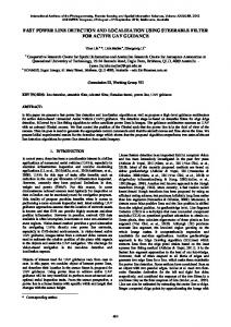
Figure 1 Robot platform (left) consisting of a Universal Robots UR10 arm, a Robotiq 3-finger gripper and RGB-D cameras for perceiving the workspace and the objects in front of the gripper, and the result of detecting and localizing the pallet (right). mounted close to the gripper (wrist camera) and the others on a rack above the base of the arm to perceive the surrounding workspace (workspace cameras). A photo of our setup and a typical scene with a pallet is shown in Figure 1. In an initial version of the part picking pipeline, we assumed both a rough estimate of the position of the pallet and that the horizontal support surface in the pallet is visible in the respective workspace camera. That is, instead of detecting and accurately localizing the pallet, we simply detected the horizontal support surface and clustered the objects thereon. The cluster being closest to the center of the detected surface was then approached to detect and accurately localize the part with the wrist camera using multi-resolution surfel registration [2]. In this paper, we present an extension to this first pipeline
Preprocessing
and an efficient method for detecting and localizing transport boxes (bins and pallets). This method is integrated into the final pipeline and we present experimental results where the setup is used to(1) detect and localize the container, (2) compute and approach an observation pose above the container with the wrist camera, and (3) segment the objects in the container and grasp them.
2
Point cloud P Edges E ⊆ P
2. Line Detection
Line Detection Lines L
Line Veri�cation (optional)
Related Work
Most approaches to bin-picking do not address mobile robots but work in static setups in which the container does not need to be detected. Buchholz et al. [3], for example, solely process depth images of the content of the box to identify graspable regions. They determine the exact pose of the object in the gripper after grasping it. In a similar fashion, Domae et al. [4] move a camera mounted on an industrial manipulator to pre-defined poses above a container with known position and orientation, and identify feasible grasps instead of objects. Drost et al. [5] use pair-wise point features to detect and localize objects in bins but also assume a static setup and only process depth images of the box content. In our approach, we address bin picking with mobile manipulators and cannot assume that the exact pose of the box is known. Instead, we detect and localize the box, and either compute and approach an observation pose for the wrist camera or extract the content of the box for further processing, e.g., object detection and localization. In own previous work [6] on bin picking with a mobile manipulator, we used a 2D laser range finder to position the robot relative to the sensed side walls of the boxes. The detected 2D bounding box was projected into the view of a 3D camera to obtain an initial guess of the 3D pose of the container and to localize objects therein. This approach, however, assumed the containers to be positioned in the height of the 2D scan plane of the laser range finder. In this paper, we do not make any assumptions on the position or orientation of the box, but only assume that the container is visible in one of the workspace cameras. A particularly challenging aspect of our setup is that not all parts of the box are visible in the RGB-D camera images (see Figure 1 for an example). Most often, only the top four edges of the side walls are visible and the top layer of the parts is captured, but the the side wall planes are usually not visible. Related works on box and cuboid detection, however, most often focus on the side walls and, in particular, on planar patches or identifiable regions that form the cuboid. Jiang et al. [7], for example, pre-segment the RGB-D images using super pixels, generate candidates sharing planes with the extracted patches, and select the most promising candidates as a mixed integer linear program. Zhang et al. [8] identify regions likely belonging to cuboids using CMPC [9], generate cuboid hypotheses and select the most likely configuration using maximum clique. Both the approaches of Jiang et al. and Zhang et al. require that especially the sides of the cuboids are visible. Jimenez et al. [10] proposed for similar scenarios to focus
1. Edge Detection
Edge Detection
Valid lines L∗
3. Container Detection
Model Sampling Tuples (l0 , l1 , . . . , ln ), l0...n ∈ L
Model Veri�cation (optional)
Continue Valid tuples (l0 , l1 , . . . , ln )∗ , l0...n ∈ L
Model Registration Transformation T , con�dence c Iterate
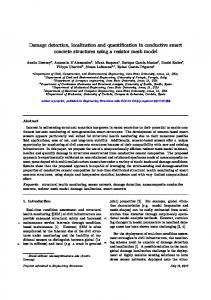
Figure 2 Overview of the processing pipeline.
on the linear edges of visible planes, combining planar and edge features. Our approach does not need to see parts of the planar surface. Berner et al. [11] also addressed visibility constraints by combining 2D contour and 3D shape primitives for the detection of industrial parts. In contrast to their work, we focus here only on the 2D contours, but also include edges detected in the RGB image. Xiao et al. [12] presented a linear approach to cuboid detection that is based on edges and corners, but requires three sides of the cuboid to be visible in the scene. Our approach is designed to reliably detect edges and to find subsets of these edges which form the top of the box we are looking for. At the same time, the involved matching provides an accurate estimate of the position and orientation of the detected container. Richtsfeld et al. [13] presented a framework for detecting and tracking objects based on a perceptual grouping of edges. In principle, the same approach could also be applied to detect and track the containers based on the detected edge points and lines. However, to instantiate the 3D wire-frame models and initialize detection and tracking, Richtsfeld et al. assume that the objects initially rest (well segmented) on a horizontal surface. Instead, our approach does not make any assumptions on the pose of the container and only uses a simple point-based model that is reliably detected in the extracted points.
3
Method
Our approach is specifically designed for situations where we can only assume the top edges of the box to be visible. It is based on extracting lines along the edges in the RGB-D images and finding the best fitting models of the container we are looking for. Referring to Figure 2, the container detection and localization pipeline is organized
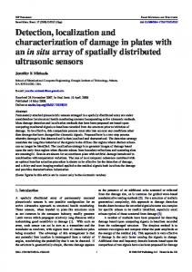
(a) Detected edges and lines
(b) Detected box
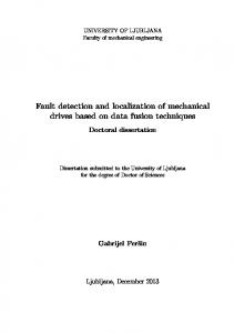
Figure 3 Container detection example: box inside an industrial shelf. (a) Detected edges (cyan: color edge, green: occluding edge) and lines (randomly colored). (b) Detected and localized container (coordinate frame indicates estimated pose of the container model).
in three stages: (1) we first detect edges in both the color image and the depth image, (2) we fit lines into the detected edge points, and (3) we sample subsets of lines and fit parameterized models of the containers to the subset. The best fitting candidate gives both the lines forming the top of the box and the pose of the box. An example of our approach applied to a typical scene is shown in Figure 3. We distinguish two variants of the pipeline: one for partially visible containers where parts of the container are occluded and one for fully visible containers. In our kitting scenario, we can assume the boxes to be fully visible and use the letter variant which is more restrictive in the individual processing steps and yields more reliable detections, but we present the details of both variants.
3.1
Edge Detection
For detecting edges, we use both the color image and the depth image, and the respective channels in the organized colored point cloud P. In the color image, we detect edge points ERGB using Canny edge detection. In the depth image, we inspect the local neighborhood of points, focus on points at depth discontinuities, and identify occluding edges by selecting those points ED that are closer to the camera. In addition, we efficiently compute local covariance matrices using a method based on integral images [14]. From the local covariance matrices, we compute local surface normals and curvature to obtain convex edges Econv and concave edges Econc , similar to [15]. For the next processing steps, we combine all points at color edges, occluding edges, and convex edges to a set of edge points E = ERGB ∪ ED ∪ Econv , E ⊆ P.
3.2
Line Fitting
Since boxes are solely composed of lines and planes (where we cannot assume the latter to be visible), we fit line segments to all extracted edge points E.
3.2.1 Line Detection Our line detection approach is based on RANSAC. In each iteration, we first select two points p and q from the set and then compute a line model (point on the line p and direction of the line q − p ), We then check the distance of all points in E to the computed line model and extract all inliers which support the line model. We use a distance threshold εd for identifying inliers. The line models with the largest number of inliers is selected as the detected line l. If the number of inliers of line l exceeds the minimum number of inliers, l is added to the set of lines L. We then remove the inliers of l from E and continue detecting other lines. If the residual number of points in E falls below a threshold or the minimum number of inliers for line segments is not reached, we stop line detection. 3.2.2 Line Validation Depending on the pipeline variant, i.e., whether we are detecting fully visible containers or not, we add two restrictions to the line detection. Detected lines which are neglected in this validation step are not contained in the final set of line segments L∗ . 1. Connectivity Restriction The inliers of a detected line may lie on different unconnected line segments. While partial occlusions can cause multiple unconnected line segments on the edges of the box if it is not fully visible, we cluster the inliers and split the detected line into multiple segments in case the box should be fully visible. If the number of points in a cluster falls below the minimum number of inliers for line segments, it is neglected. 2. Length Restriction In case the container is fully visible, we neglect line segments which are shorter than the shortest edge in the model and longer than the longest edge in the model. To account for noise, missing edge points, or other errors, we allow a deviation of 20 % from these thresholds.
If we use the pipeline to also detect partially occluded containers, we skip both restrictions and use the originally detected lines, i.e., L∗ = L, or only check the maximum edge length. Detected lines are shown for an example in Figure 3a.
3.3
Container Fitting
After all line segments have been extracted, we start to detect and localize the container in a RANSAC-based paradigm: in each iteration of the detection, we first sample a subset of line segments and then register the model of the container with the sampled line segments to obtain both a pose estimate and a measure of overlap between the line segments and the model. 3.3.1 Model Sampling For detecting the container, we select a subset of the detected line segments and collect the inliers of the sampled line segments to obtain a single point cloud for later processing steps. In case of fully visible containers, we select n line segments where n is the number of line segments in the parameterized model. That is, we sample as many line segments as contained in the model of the container. As a result, we obtain tuples of line segments (l0 , . . . , ln ). If the container is not fully visible, we also randomize the number of sampled line segments (2 to n) in each iteration of the container detection. Samples with a larger number of line segments obtain higher confidences in the model registration and are thus favored over samples with fewer line segments. In order to avoid repetitively re-checking the same tuple, we use a hash table in which sampled tuples are marked as being processed. In case no unprocessed tuple can be found, we stop the container detection. 3.3.2 Model Validation Since the final registration in the container detection is the computationally most expensive step, we can considerably reduce computation time by immediately neglecting tuples of line segments which are not compatible with the model. In the case of our transport boxes, for example, the model contains four edges which are pairwise parallel and perpendicular to each other. Consequently, incompatible tuples can be easily be skipped in later processing steps if the sampled edges do not show the expected relations. In our implementation, we simply compute the angles between the first sampled line segment to all other line segments. In case of a fully visible container, we expect one of the other line segments to be parallel and the other two line segments to be perpendicular to the first one. If not, we neglect the sampled tuple of line segments. In case the box is not fully visible, we either skip this step or allow subsets of these constraints, e.g., finding another edge which is either parallel or perpendicular in case only two line segments have been sampled.
3.3.3 Model Registration If the tuple of sampled line segments is valid, we continue to register the model against the sampled line segments. For the model registration, we sample points from the given parameterized container model in order to obtain a source point cloud P for registration (in the simplest case the model is simply given by the length and width of the box). In addition, we extract the inliers of the sampled segments to form a single target point cloud Q for registration. In contrast to extracting the inliers for the target point cloud, the source point cloud of the model only needs to be sampled only once. Iterative registration algorithms align pairs of 3D point clouds by alternately searching for correspondences between the clouds and minimizing the distances between matches. In order to align a point cloud P with a point cloud Q, the ICP algorithm searches for closest neighbors in Q for points p i ∈ P and minimizes the point-to-point disT) (T T p i of the set of found correspondences tances d i j = q j −T C in order to find the optimal transformation T ∗ : T ∗ = arm min T
∑
T) (T
kdd i j k2 .
(1)
(i j)∈C
As a result, points in P are dragged onto their corresponding points in Q. Assuming (predominantly) correct correspondences, the ICP algorithm can reliably register point clouds (if the initial alignment is not considerably off). In addition to the transformation T ∗ , we also compute a confidence c that is based on the overlap between the model and the sampled line segments: c=
|C| , |P|
(2)
where |C| is the number of corresponding points within a predefined distance tolerance εd and |P| is the number of points in the generated model point cloud. That is, the more points from the container model find a corresponding point in the inliers of the sampled line segments, the more confident are we in the estimated transformation. In case of a complete overlap (and a fully visible container), the confidence c is roughly 1. Naturally, for containers that are not fully visible, the confidence can only reflect the amount of overlap and the size of the container that is not occluded, respectively. For fully visible containers, however, the confidence can be used to drastically reduce the processing time by immediately terminating the detection once the desired number of detections (in our scenarios usually only one) with a confidence above a user-defined threshold has been found. In addition, the confidence can be used in the course of the registration to detect if the registration got stuck in a local minimum. This check together with a maximum number of iterations allows for limiting the execution time of this processing step. While the initial version of the pipeline [1] assumed a presegmentation and an initial pose estimate, in this method we do not make any assumptions and, instead, initialize the model to lie in the origin of the camera coordinate frame.
4
Evaluation
In order to assess the performance of our container detection pipeline, we have conducted a series of experiments with the robot setup shown in Figure 1. The system consists of a Universal Robots UR10 arm, a Robotiq 3-finger gripper and three Asus Xtion cameras, one mounted on the arm close to the gripper, and two mounted on a rack above the arm. We focus on two criteria in our evaluation: the success rate and the overall cycle time. In the first series of experiments, we evaluate the performance of our approach for detecting boxes, pallets, and scenes not containing the container we are looking for. In the second series, the container detection was integrated into the complete perception and grasping pipeline from our previous work [1] and used for grasping two different automotive parts in boxes.
4.1
Detecting Boxes and Pallets
In order to assess the performance of our container detection pipeline, we have captured RGB-D images in different scenes with boxes, scenes with pallets and scenes not containing the container we have been looking for. In case the container being searched for is not contained in the scene, we expect our pipeline to correctly report that no container was found. This is a special requirement of the industrial end-user: whenever failures are detected such as containers not being in the vicinity of the pose stored in the logistics system or containers not containing any objects, the robot is expected to report this error to the logistics system. For both types of containers (boxes and pallets) we captured images where the container is fully visible—standard case—and where the container is partially occluded. As mentioned in Section 3, we distinguish these two cases and use different variants of the pipeline. We report the detailed results of our experiments in Table 1. In case of full visibility, we used the restrictive variant and a confidence threshold εc = 0.9. For the scenes with partially occluded containers, we use the less restrictive variant of the pipeline without the confidence check. That is, for the 75 % occlusion and the 50 % occlusion scenes, the line validity and model confidence checks were skipped while the model validity check was relaxed, i.e., not re-
50 % 75 % Full vis.
In order to avoid orientation ambiguities (due to the symmetry in rectangular shapes), we register the model two times: first with no initial orientation and then with a rotation of π2 around the z-axis, i.e., the axis pointing into the depth image. The result with a higher confidence is chosen as the estimated pose and confidence, respectively. Since the source point cloud is generated in a local frame, the initial deviation from the container pose may be large. In order to obtain a rough initial alignment in the first iterations and obtaining an accurate pose estimate in later iterations, we use different distance thresholds between corresponding points: a larger distance in the first iterations, and smaller distances later for refining the estimated transformation. A typical detection result is shown in Figure 3b.
Container
Total
True
False
Runtime
Box Pallet None
100 100 100
100 100 100
0 0 0
105 ± 23 ms 98 ± 22 ms 141 ± 28 ms
Box Pallet
100 100
100 100
0 0
111 ± 24 ms 102 ± 27 ms
Box Pallet
100 100
96 95
2 1
131 ± 39 ms 139 ± 33 ms
Table 1 Detection results and runtimes.
quiring a particular number of parallel and perpendicular line segments, but simply neglecting the sample when the other edge(s) are neither parallel nor perpendicular. In all experiments, the results of our detection pipeline have been visually inspected to assess detection success. In order to estimate the average processing time per frame, each captured RGB-D image was processed 10 000 times on a single core of an Intel Core i7-3740QM CPU @ 2.7 GHz without parallelization and the measured times have been averaged. Overall, we achieve a frame rate of 6.5 −10 Hz for detecting and localizing both boxes and pallets. This is more than sufficient for our application. For our targeted scenario of fully visible containers, in all 100 cases both container types are reliably detected and localized (without any false positives). The RANSAC paradigm in all processing steps makes the approach particularly robust. For the scenes where the container was partially occluded, the method does not achieve a 100 % success rate and also produces a small number of false positives. Naturally, the more of the container is occluded the higher is the risk of false positives. With increasing occlusions, the scene may contain many other edges which better fit the container model than the edges and line segments measured on the real physical container. Furthermore, since more line segments and different configurations of samples (different numbers of line segments per sample) are drawn, the processing time until a good sample is found slightly increases. Consequently, we ensure full visibility of containers in our application scenario.
4.2
Integrated Experiments
In order to assess the performance of the overall system with the container detection integrated, we have conducted two series of experiments where in each series we grasped 20 parts from a transport box. The overall perception and grasping pipeline for these experiments is implemented as follows: (1) Using the workspace camera, the container is detected and localized. (2) An observation pose above the container is computed and approached with the wrist camera. The observation pose guarantees full visibility of the container taking into account its pose and the camera model.
Time Initial Detection
Observation
Grasping
Removal
(a) Picking a tube connector (from top to bottom: workspace camera image, wrist camera image, 3D visualization).
Execution times Component Container detection Part segmentation Grasping a found part Overall cycle time
Success rate
Mean
Stdev
Min
Max
0.121 s 0.077 s 8.812 s
0.034 s 0.021 s 0.429 s
0.037 s 0.032 s 5.012 s
0.198 s 0.089 s 13.673 s
27.342 s
2.341 s
21.934 s
37.548 s
Successful / Total 20 / 20 20 / 20 20 / 20
(100 %) (100 %) (100 %)
(b) Execution times per component and overall cycle times. Cycle times include moving back to the initial pose.
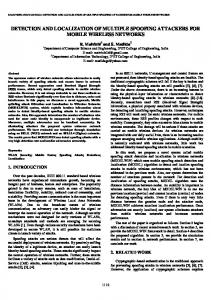
Figure 4 Success rates and cycle times for picking tube connectors. In all experiments, the robot was able to localize the container, approach the observation pose, segment the container content, and grasp a part (success rate of 100 %).
(3) Using the wrist camera, the container is detected and localized. Measurements belonging to the content of container are extracted. (4) The extracted content measurements are segmented and further processed to compute grasping points and end-effector poses for grasping. The first object is a tube connector for engines which is stored unorganized in larger boxes (57×38×31 cm). The second object is an engine support part which is stored well organized in smaller boxes (38×29×22 cm). For both objects, we run a total of 20 experiments in which the task is to localize the container and to grasp a part. In all experiments we assume the boxes to be fully visible. The container detection pipeline for all experiments is configured as follows: we use all three edge types (color, occluding, and convex) to extract edge points in local windows of 50 pixels. We use a distance threshold of 2 cm for
line detection and a minimum number of inliers per line of 50 points. Clustering of the detected lines to line segments is enabled using a maximum distance of 5 cm between points in the same cluster. In addition, we neglect line segments whose lengths fall below or above, respectively, the minimum and maximum edge lengths in the model by more than 20 %. For detecting the container, we sample four line segments in each iteration and check the validity of the samples by neglecting samples not showing one other parallel line and two other perpendicular lines (angle threshold of 20◦ ). The model registration starts without a distance threshold (εd = ∞), and then linearly decreases from 1 m to 2.5 cm—the final distance threshold for the confidence check. The model confidence check is enabled and we accept registered models with a confidence of c > 0.9. In order to determine grasps for the tube connectors in the extracted container content, we cluster the extracted point
Time Initial Detection
Observation
Grasping
Removal
(a) Picking a tube connector (from top to bottom: workspace camera image, wrist camera image, 3D visualization).
Execution times Component Container detection Part segmentation Grasping a found part Overall cycle time
Success rate
Mean
Stdev
Min
Max
0.132 s 0.021 s 7.741 s
0.041 s 0.009 s 0.561 s
0.033 s 0.005 s 5.642 s
0.202 s 0.087 s 15.001 s
25.145 s
3.091 s
19.885 s
31.939 s
Successful / Total 20 / 20 20 / 20 20 / 20
(100 %) (100 %) (100 %)
(b) Execution times per component and overall cycle times. Cycle times include moving back to the initial pose.
Figure 5 Success rates and cycle times for picking engine support parts, again achieving a success rate of 100 %.
cloud into cylinders and select the centroid of the highest cylinder (with sufficient space around it for the gripper) as the grasping point. The orientation of the grasp pose is chosen according to the principal axis of the cylinder to be grasped and aligned with the local coordinate frame of the detected container in order to approach the part straight from the top of the container. Examples of the segmented cylinders and the computed grasp poses can be seen in Figure 4 together with the detailed results of all 20 experiments. We achieve a success rate of 100 % at an average cycle time of 27 s. The overall cycle time includes moving the arm from its initial pose to the computed observation pose, grasping the part and moving back to the initial pose. Most of the cycle time is spent on motion planning and execution, with perception contributing only about 1 %. In contrast to the tube connectors which are stored in an unorganized pile in the box, the engine support parts are well organized and pose a depalletizing task. In order to
segment the parts in the container and to compute grasping poses, we filter out the packaging material by removing all points on and under the horizontal support surface in the container and cluster the residual points. The centroids and the principal axes of the clusters are used to compute the grasping poses in a similar fashion as in our previous work [16]. Examples of the detected container, the segmented parts and the computed grasping poses can be seen in Figure 5 together with the measured success rates and processing times in these experiments. As for the tube connectors, we also achieve a success rate of 100 % for the engine support parts at an average cycle time 25 s. Again, most of the cycle time is spent on motion planning and execution. In our experiments, we only focus on fast perception components and it is expected that the overall cycle times can be considerably reduced by improving and speeding up motion planning. In addition, in our lab setup, we do not op-
erate the robot at full speed for safety reasons. As can be seen in both experiment series, the storage containers are reliably detected and localized, and even the simple segmentation methods for obtaining grasp poses are sufficient in this setup. Since the content of the containers is extracted as an organized colored RGB-D point cloud, the simple segmentation methods can be easily replaced by more sophisticated approaches, e.g., that of Domae et al. [4] to identify graspable points or that of Drost et al. [5] or Berner et al. [11] to accurately localize the parts.
5
Conclusions
For bin picking and depalletizing with a mobile manipulator, we have presented an efficient pipeline for detecting boxes and pallets. Since in our scenario, most often only the top edges of the containers are visible, the proposed method is based on detecting edges in the color image and the depth image. We fit line segments to the extracted edge points and sample subsets of the detected line segments as hypotheses for potential container inliers. An ICP-based registration of the known container model (simple parameterized model of the top edges) provides both a pose estimation and a detection confidence. In a series of experiments, we evaluated the performance of our approach for both fully visible and partially occluded containers and achieved for fully visible containers success rates of 100 % without false positives at frame rates of up to 10 Hz. Only for scenes where larger parts of the container have been occluded the success rates dropped and few false positives have been generated. Consequently, in our application scenario, we ensure visibility and use the more restrictive variant of the pipeline with a strict threshold on the detection confidence. In two final series of experiments, the container detection was integrated into the complete perception and grasping pipeline. The containers are reliably detected with both the workspace camera above the arm, and the wrist camera mounted on the arm close the gripper. We then segmented the parts in the container and computed grasping poses using two simple methods as application examples. We could show success rates of 100 % for grasping two different parts at overall cycle times of roughly 25 s (including motion planning and execution). In this paper, we have only conducted experiments with the lab setup used for development. It is a matter of ongoing and future work to run more experiments on the final demonstrator setup at the industrial end-user site as has been done in our previous work [1].
Acknowledgments This work has received funding from the European Union’s Seventh Framework Programme for research, technological development and demonstration under grant agreement no 610917 (STAMINA).
References [1] D. Holz, A. Topalidou-Kyniazopoulou, J. Stückler, and S. Behnke. Real-time object detection, localization and verification for fast robotic depalletizing. In Proc. of the IEEE/RSJ International Conference on Intelligent Robots and Systems (IROS), pages 1459–1466, 2015. [2] J. Stückler and S. Behnke. Multi-resolution surfel maps for efficient dense 3D modeling and tracking. Journal of Visual Communication and Image Representation, 25(1):137–147, 2014. [3] D. Buchholz, D. Kubus, I. Weidauer, A. Scholz, and F. M. Wahl. Combining visual and inertial features for efficient grasping and binpicking. In Proc. of the IEEE International Conference on Robotics and Automation (ICRA), pages 875–882, 2014. [4] Y. Domae, H. Okuda, Y. Taguchi, K. Sumi, and T. Hirai. Fast graspability evaluation on single depth maps for bin picking with general grippers. In Proc. of the IEEE International Conference on Robotics and Automation (ICRA), pages 1997–2004, 2014. [5] B. Drost, M. Ulrich, N. Navab, and S. Ilic. Model globally, match locally: Efficient and robust 3d object recognition. In Proc. of the IEEE Conference on Computer Vision and Pattern Recognition (CVPR), pages 998–1005, 2010. [6] D. Holz, M. Nieuwenhuisen, D. Droeschel, J. Stückler, A. Berner, J. Li, R. Klein, and S. Behnke. Active recognition and manipulation for mobile robot bin picking. In Florian Röhrbein, Germano Veiga, and Ciro Natale, editors, Gearing up and accelerating crossfertilization between academic and industrial robotics research in Europe: Technology transfer experiments from the ECHORD project, volume 94 of Springer Tracts in Advanced Robotics, pages 133–153. Springer International Publishing, 2014. [7] H. Jiang and J. Xiao. A linear approach to matching cuboids in RGBD images. In Proc. of the IEEE Conference on Computer Vision and Pattern Recognition (CVPR), pages 2171–2178, 2013. [8] H. Zhang, X. Chen, Y. Zhang, J. Li, Q. Li, and X. Wang. Cuboids detection in RGB-D images via maximum weighted clique. In Prof. of the IEEE International Conference on Multimedia and Expo (ICME), 2015. [9] J. Carreira and C. Sminchisescu. CPMC: automatic object segmentation using constrained parametric min-cuts. IEEE Transactions on Pattern Analysis and Machine Intelligence (TPAMI), 34(7):1312– 1328, 2012. [10] David Jimenez Cabello, Sven Behnke, and Daniel Pizarro Perez. Linear plane border: A primitive for range images combining depth edges and surface points. In Proceedings of 8th International Conference on Computer Vision Theory and Applications (VISAPP), 2013. [11] Alexander Berner, Jun Li, Dirk Holz, Jörg Stückler, Sven Behnke, and Reinhard Klein. Combining contour and shape primitives for object detection and pose estimation of prefabricated parts. In Proceedings of IEEE International Conference on Image Processing (ICIP), 2013. [12] J. Xiao, B. C. Russell, , and A. Torralba. Localizing 3D cuboids in single-view images. In Advances in Neural Information Processing Systems (NIPS), 2012. [13] A. Richtsfeld, T. Mörwald, M. Zillich, and M. Vincze. Taking in Shape: Detection and tracking of basic 3D shapes in a robotics context. In Proc. of the Computer Vision Winter Workshop (CVWW), 2010. [14] S. Holzer, R. B. Rusu, M. Dixon, S. Gedikli, and N. Navab. Adaptive neighborhood selection for real-time surface normal estimation from organized point cloud data using integral images. In Proc. of the IEEE/RSJ International Conference on Intelligent Robots and Systems (IROS), pages 2684–2689, 2012. [15] C. Choi, A. J.B. Trevor, and H. I. Christensen. RGB-D edge detection and edge-based registration. In Proc. of the IEEE/RSJ International Conference on Intelligent Robots and Systems (IROS), pages 1568–1575, 2013. [16] Jörg Stückler, Ricarda Steffens, Dirk Holz, and Sven Behnke. Efficient 3D object perception and grasp planning for mobile manipulation in domestic environments. Robotics and Autonomous Systems, 61(10):1106–1115, 2013.