pion 3D Stinger), and Fanuc (iRVision 3D area sensor). Some vendors offer integrated solutions for bin picking. One example is Scape Technologies A/S, which ...
IEEE/RSJ International Conference on Intelligent Robots and Systems (IROS), Hamburg, Germany, 2015.
Real-Time Object Detection, Localization and Verification for Fast Robotic Depalletizing Dirk Holz, Angeliki Topalidou-Kyniazopoulou, J¨org St¨uckler, and Sven Behnke Abstract— Depalletizing is a challenging task for manipulation robots. Key to successful application are not only robustness of the approach, but also achievable cycle times in order to keep up with the rest of the process. In this paper, we propose a system for depalletizing and a complete pipeline for detecting and localizing objects as well as verifying that the found object does not deviate from the known object model, e.g., if it is not the object to pick. In order to achieve high robustness (e.g., with respect to different lighting conditions) and generality with respect to the objects to pick, our approach is based on multi-resolution surfel models. All components (both software and hardware) allow operation at high frame rates and, thus, allow for low cycle times. In experiments, we demonstrate depalletizing of automotive and other prefabricated parts with both high reliability (w.r.t. success rates) and efficiency (w.r.t. low cycle times).
I. I NTRODUCTION In the past decade(s), the paradigm of car production has shifted from mass production to increased customization of products (build-to-order). More customized products with increased numbers of assembly combinations implicitly mean more components to store, transport and feed to the production line. Due to this variability of the production and to the diversity of suppliers and parts, part handling during the assembly stages in the automotive industry is the only task with automation levels below 30%. Following this trend, kitting type distribution has developed massively in the automotive industry over the past few years. The main idea is to concentrate the value added on the production line and decentralize re-packing operations. Kitting operations are usually performed by operators called pickers. These pickers collect parts as needed from containers they are stored in, i.e., bins and pallets. Once complete, the kits are delivered to the production line and synchronized with the car to be produced. The full automation of such tasks will not only have a huge impact in the automotive industry but will also act as a cornerstone in the development of advanced mobile robotic manipulators capable of dealing with semi-structured environments, thus opening new possibilities for manufacturing in general. In the course of a larger project on kitting using mobile manipulators, we have developed a system for automated grasping of parts from pallets. This task comprises two major This project has received funding from the European Unions Seventh Framework Programme for research, technological development and demonstration under grant agreement no 610917 (STAMINA). We thank all project partners for the collaboration, integration and testing. All authors are with the Autonomous Intelligent Systems Group, Computer Science Institute VI, University of Bonn, 53113 Bonn, Germany {holz, topalido, stueckler, behnke}@ais.uni-bonn.de
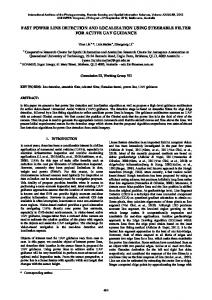
Fig. 1: Hardware setup with pallet. The platform is composed of a Universal Robots UR10 arm, a Robotiq 3-finger gripper, three Asus Xtion Pro RGB-D camera for perceiving the workspace, and a PrimeSense Carmine RGB-D camera at the wrist for close-range object perception.
sub-problems: 1) object perception and 2) motion planning and execution. In this paper, we focus on the former and present a complete pipeline for object detection, localization and verification where all components (both software and hardware) allow operation at high frame rates. We thereby explicitly exploit the characteristics of depalletizing problems such as well-separated parts (under the assumption that intermediate packaging is removed already). 1) We segment the pallet, its support surface and possible object candidates thereon in real-time [1]. 2) By efficiently registering multi-resolution surfel models [2], we accurately localize the object in real-time (after moving gripper and wrist camera to a potential object candidate). 3) We use the matching score to detect deviations from the learned object model (e.g., damages) and to detect wrong objects. The whole perception pipeline needs less than 0.5 s for execution (excluding motion planning and execution). With our hardware setup (Fig. 1), we achieve cycle times of 13 s for grasping an object on the pallet (starting from the initial safety pose of the arm used when the base is moving). In addition to real-time applicability, we focus on the generality of our approach w.r.t. to the objects to be picked. While the majority of related works focuses on particular aspects such as 2D contours in camera images [3], [4], [5],
[6], distinct 2D and 3D keypoints and feature descriptors [7], [8], [9], [10], or geometric primitives [11], we densely match RGB-D measurements to object models using multiresolution surfel maps (MRSMaps) [2]. In this way, we make full use of the available image information without relying on an explicit feature extraction stage. II. R ELATED W ORK Using vision sensors for object detection and pose estimation in industrial robotics applications has been focus of research within the last decades. Early work used very specific geometric features of objects which are found in intensity images. Rothwell et al. [3], for example, use invariants of such geometric features under perspective transformation for fast indexing and matching of observed edges of planar shapes to a model database. Other works, e.g. Rahardja and Kosaka [4], use singulated geometric shapes such as circular or polygonal structures on the objects as landmark features to find the pose of the object. Such features have also been extracted from range images for object detection and pose estimation—one prominent early example being the 3DPO system of Bolles and Horaud [5]. A. Bin Picking and Depalletizing Research More recently, Papazov et al. [7] use depth images of a Microsoft Kinect sensor to find objects in a scene for picking and placing by a robot. Their recognition approach compares surfel-pair matches between scene point cloud and object model in a RANSAC scheme for detection and pose estimation. Drost et al. [8] propose to use Hough voting with surfel-pair matches instead. This approach has been extended by Choi et al. [9] with oriented points on contours of the object. They acquire point clouds of small objects in a transport box, and grasp them with a high success rate with an industrial robot arm. Skotheim et al. [10] also propose a voting scheme based on pairs of oriented points in 3D point clouds. They mounted a laser triangulation sensor directly at the wrist of the robot such that it can scan the object from arbitrary view points. Our approach finds a highly accurate pose of the object through segmentation and dense model alignment by exploiting that in a depalletizing scenario, a coarse initial guess of the object orientation on the palette is typically known. Pretto et al. [6] use a monocular vision system in a bin picking scenario, i.e., they find objects using intensity images. The approach is based on matching contours in the scene with the object model, assuming planar surfaces on the objects. They report cycle times of up to 7 s in a statically mounted robot setup. Our approach does not make such strong assumptions on object shape. Brachmann et al. [12] use a learned object representation combining dense 3D object coordinate labeling and dense class labelling for textured and texture-less objects. They achieve high detection accuracies and runtimes (depending on the parameterization) around 500 ms, but only for single objects as opposed to scenes containing multiple instances of the same object.
In own previous work [11], we have developed an approach to mobile robot bin picking where objects are modeled using geometric shape primitives. Compounds of both 2D contour and 3D shape primitives are found by graph matching of primitives detected in 3D point clouds. Our new approach is less restrictive in the sense that objects need not to be composed from geometric primitives. B. Commercial Bin Picking Solutions Feeding small unordered parts from transport boxes to production lines is still mostly done by vibratory bowl feeders. These machines are noisy, large, and lack flexibility. Larger parts are mostly handled manually. Robotic part feeders grasp individual parts, which makes them more flexible. Halfway between vibratory bowl feeders and robot bin pickers are solutions which separate parts before detection and grasping, which simplifies these tasks. Adapt Technologies AnyFeeder, which is widely used in many industries, is one example for this approach. It is, however, limited to small parts. Through advances in 3D sensing, computing, and algorithms, more and more industrial part feeding applications can be automated by robot bin picking, which is mostly used for larger parts. An increasing number of companies offer 3D sensors, which are needed to acquire the geometry of the parts inside the box. Examples include Isra Vision (3D SHAPEscan), Sick (IVC-3D, Ruler), GFM (ShapeScan3D, AreaScan3D), Leutze (LPS 36), Tordivel (Scorpion 3D Stinger), LMI Technologies (Gocator), ShapeDrive (SD-1K-V ), and Mesa (SR4000). These 3D sensors rely on special illumination of the scene, mostly by moving laser lines, but also by varying stripe patterns or phase-modulated light. Some companies offer affordable 3D sensors for consumer applications, such as human-computer interaction. Examples include Microsoft (Kinect), Asus (Xtion), Intel (Creative Interactive Gesture Camera), and Leap Motion (hand gesture sensor). Software solutions for detecting parts and estimating their pose from 3D scans are offered by several vendors, such as Aqsense (SAL3D Match3D), Isra Vision, Vision++ (BinPicker++), VMT Vision, MVTec (Halcon), Tordivel (Scorpion 3D Stinger), and Fanuc (iRVision 3D area sensor). Some vendors offer integrated solutions for bin picking. One example is Scape Technologies A/S, which places a camera on the robot end-effector. Images are taken with active illumination from two perspectives for depth reconstruction. Parts with mostly simple geometry, like disks, cylinders, pipes, and boxes are picked with a cycle time of less then 10 s. Another example for mounting the sensor on the robot arm is the bin picking solution of Faude, which uses a Leuze Line Profile Sensor on a Universal Robots arm. In contrast, the bin-picking system of VMT Vision Machine Technic Bildverarbeitungssysteme GmbH, acquires the scene by a laser scanner moving on a linear axis above the bin. Placing the 3D sensor above the bin has the advantage that the sensor can make the next scan while the robot is delivering a part. Other examples for this approach include SICK’s PLB vision system and Liebherrs bin picking
Workspace camera
Wrist camera
RGB-D point cloud
Grasp Command Object Model
RGB-D point cloud
Workspace and pallet perception Object Candidates
Candidate Selection / Motion Planning
Endeffector Pose
Motion execution
Candidate Positition
Object localization and verification Object Pose
Grasp Selection / Motion Planning
Motion execution
Success State
Fig. 2: Perception pipeline and overall data flow.
solution, which equips the gripper with additional axis for collision-free part picking, and iRob Feeder developed by PROFACTOR GmbH and IH Tech. These examples might suggest that industrial bin picking and depalletizing are solved, but this is not the case. Successful demonstrations usually require significant engineering efforts for each use-case. Many technological advances are needed to make the systems easy to set up, flexible, reliable, fast, and cost effective. III. A PPROACH Referring to the pipeline overview in Fig. 2 and the platform description in Fig. 4a, our object perception and grasping pipeline comprises the following steps. 1) Using the workspace camera, we detect the pallet and object candidates. If no object is found (e.g., when the pallet is cleared) the robot stops and reports to the operator. 2) The wrist camera is positioned on top of the object candidate being closest to the pallet center. 3) Using the wrist camera, we recognize and localize the part. The quality of the found matching is used for object verification. Poor matching quality indicates that a wrong object was found. In case of a wrong object, the robot stops, reports the errors and waits for an operator instruction to continue its operation. 4) A grasp is selected from a set of predefined grasps and the robot plans a motion to reach it. 5) The robot grasps the object and plans a motion to the secure tray (used as a dummy for subsequent tasks). The robot then follows the planned trajectory to move the object over the secure tray, releases the object and moves back to its initial pose. A. Initial Part Detection The task of picking an object from the pallet starts, respectively, when navigation has already taken place and the robot is positioned in the vicinity of the pallet. In order to compensate for potential misalignments or inaccuracies in the estimated poses of robot and pallet, we first use the workspace camera to find the pallet and to get a first
estimate of where to find potential object candidates. Under the assumption that we know the side to which to find the pallet, we acquire images of the respective workspace camera and search for horizontal support surfaces above the ground plane. In order to achieve real-time performance, we efficiently compute local surface normals using integral images, extract points whose normals point along the gravity vector, and fit planes perpendicular to the normals of the extracted points [1]. Referring to Fig. 3, we restrict these extracted (horizontal) planes to lie in the region where we expect the pallet to be found, e.g., not outside the robot’s reachable workspace, and neglect others such as the ground plane. In order to find potential object candidates, we then select the most dominant support plane, compute both convex hull and minimum area bounding box, and select all RGB-D measurements lying within these polygons and above the extracted support plane. Thereby, we slightly shrink the limiting polygons in order to neglect measurements caused by the exterior walls of the pallet. The selected points are clustered (to obtain object candidates), and the cluster being closest to the center of the pallet is selected to get approached first. After approaching the selected object candidate with the end effector, the same procedure is repeated with the wrist camera in order to separate potential objects from the support surface. Using the centroid of the extracted cluster as well as the main axes (as derived from principal component analysis), we obtain a rough initial guess of the object pose. With the subsequent registration stage, it does not matter when objects are not well segmented (connected in a single cluster) or when the initial pose estimate is inaccurate. B. Object Pose Refinement We use multi-resolution surfel maps (MRSMaps, [2]) as a concise dense representation of the RGB-D measurements on an object. In a training phase, we collect one to several views on the object whose view poses can be optimized using pose graph optimization techniques. Our pose refinement approach is closely related to our soft-assignment surfel registration approach in [13] for registering sparse 3D point clouds. Here, for segments with only a few measurements, the softassignment method improves robustness and accuracy over the registration approach in [2] which uses one-to-one surfel associations with trilinear interpolation instead. We want to register the points P = {p1 , . . . , pP } in a segment with the points Q = {q1 , . . . , qQ } represented in the object model MRSMap. Instead of considering each point individually, we map the RGB-D segment into a MRSMap and match surfels, i.e., p(P | θ, Q) ≈
N Y
p(xi | θ, Y )Px,i .
(1)
i=1
By this, several orders of magnitudes less map elements are used for registration. Similarly, the registration of two MRSMaps is treated as the registration of their point sets. We denote the set of surfels in the scene (the measured segment) by X = {x1 , . . . , xN } and write Y = {y1 , . . . , yM } for
Fig. 3: Typical results of detection and localization. From left to right: workspace camera point cloud with extracted object candidates (cyan) and selected object (magenta), and wrist camera point clouds during localization, approach and grasping.
the set of model surfels in the object model map. A surfel xi summarizes its attributed Px,i points by their sample mean µx,i and covariance Σx,i . We assume that scene and model can be aligned by a rigid 6 degree-of-freedom (DoF) transformation T (θ) from scene to model. We explain each transformed scene surfel as an observation from a mixture model, similar as in the coherent point drift (CPD) method [14]. A surfel xi is observed under the mixture defined by the model surfels and an additional uniform component that explains outliers, i.e., p(xi | θ, Y ) =
M +1 X
p(ci,j ) p(xi | ci,j , θ, Y ).
(2)
j=1
The binary variable ci indicates the association of xi to one of the mixture components. The model is a mixture on Gaussian components for the M model surfels that measure the matching likelihood between the surfels through p(xi | ci,j , θ, Y ) := � � N T (θ)µx,i ; µy,j , Σy,j + R(θ)Σx,i R(θ)T + σj2 I , (3) where σj = 21 ρ−1 y,j is a standard deviation that we adapt to the resolution ρy,j of the model surfel. We set the likelihood of the uniform mixture component to a constant. This way, we do not make a hard association decision for each surfel, but a scene surfel is associated to multiple model surfels. The alignment pose θ is estimated through maximization of the logarithm of the joint data-likelihood ln p(P | θ, Q) ≈
N X
Px,i ln
M +1 X
p(ci,j ) p(xi | ci,j , θ, Y ).
j=1
i=1
(4) We optimize this objective function through expectationmaximization (EM) [15]. In the M-step, the latest estimate q for the distribution over component associations is held fixed to optimize for the pose θ θb = arg max θ
N X i=1
Px,i
M +1 X
q(ci,j ) ln p(xi | ci,j , θ, Y ). (5)
j=1
This optimization is efficiently performed using the Levenberg-Marquardt (LM) method as in [2].
The E-step obtains a new optimum qb for the distribution q by the conditional likelihood of the cluster associations given the latest pose estimate θ p(ci,j ) p(xi | ci,j , θ, Y ) qb(ci,j ) = PM +1 . 0 0 j 0 =1 p(ci,j ) p(xi | ci,j , θ, Y )
(6)
In order to evaluate these soft assignments, we perform a local search in the MRSMap of the model. We first look up the surfel available on the finest resolution in the model map at the transformed mean position of the scene surfel. We consider this surfel and its neighbors in a local volume for soft association whose size scales with the resolution of the surfel. C. Object Verification After pose refinement, we verify that the observed segment fits to the object model for the estimated pose. By this, we can find wrong registration results if observed and assumed object match as well as detect if a wrong object has been placed on the pallet. In such cases, the robot stops immediately and reports to the operator (as per specification of the task). We establish one-to-one associations of surfels between segment and object model map, and determine the observation likelihood using these associations similar as in Eq 4. In addition to the surfel observation likelihood given by the matching of their Gaussian statistics, we now also consider occlusions by model surfels of the observed RGB-D image as highly unlikely. Such occlusions can be efficiently determined by projecting model surfels into the RGB-D image given the estimated alignment pose and determining the difference in depth at the projected pixel position. The resulting segment observation likelihood is compared with a baseline observation likelihood of observing the model MRSMap by itself, in order to avoid the calculation of the partition function of the joint data likelihood. We determine a detection confidence from the rescaled ratio of both log likelihoods thresholded between 0 and 1. D. Motion Planning and Execution Motion planning and execution are based on MoveIt [16]. In each pipeline cycle, we need a series of individual motions in order to verify, pick, and place an object. Since planning
Initial pose Grasping (right) Releasing (Lab) or Grasping (left)
(a) System setup with labeled components
(b) Example grids in different heights and example poses
Fig. 4: Setup and pre-computed trajectories: shown are (a) the hardware platform used in the lab experiments and (b) a frontal view of the grids of sampled poses as well as common arm poses including the initial pose during navigation, a typical grasping pose to the right side of the robot and the pose for releasing parts in the lab experiments or for grasping on the left (b).
every single motion is a time consuming task, we use precomputed motions whenever the arm is moved between predefined poses. Pre-computed trajectories are planned and stored only once and can be retrieved whenever the robot needs to follow the resulting motion. For being able to use pre-computed motions, we define several fixed poses, e.g., the initial pose of the robot (used while navigating with the mobile base), and the pose where objects are placed (placement pose). In addition, we define rectangular grids (Fig. 4b) of poses to the sides of the robot and above the maximum height where we assume pallets. For every pose in the grid, we pre-compute a joint trajectory from the initial pose to the grid pose as well as from the grid pose to an intermediate pose and the placement pose. Whenever possible, the robot uses pre-computed trajectories to reach its goal, or approaches the closest pose reachable with precomputed trajectories and only plans the residual motion from that pose on. By this means, we only need to plan short trajectories that are computed faster and only check if collisions exist between the robot and the environment for every pre-computed motion before execution, which is not as time consuming as motion planning. In an average picking cycle, following this scheme reduces motion planning time by more than 25 %. For executing planned and pre-computed motions, we use standard components such as the standard drivers for arm and gripper as made available by the manufacturers within the ROS Industrial initiative1 . IV. E XPERIMENTS AND R ESULTS In order to assess robustness and performance of our approach, we conducted a series of experiments of both individual components and the integrated platform. As evaluation criteria, we focus on the success rates and the execution times of the individual components and the overall cycle times (for picking an object from the pallet) of the integrated system. 1 For
more information on ROS industrial, see http://rosindustrial.org.
(a) Parts used in the experiment
Object
Mean Stdev Min
Max
Correct object (“cross clamp”) Similar cross clamp (pose 1) Similar cross clamp (pose 2) Small starter Large starter Smaller cross clamp
0.901 0 0.407 0 0.505 0
0.951 0 0.452 0 0.581 0
0.024 0 0.034 0 0.055 0
0.853 0 0.299 0 0.398 0
(b) Object detection confidences
Fig. 5: Object detection and verification. (a) Used parts, from left to right: correct object, different cross clamp in poses 1 and 2, small starter, large starter, and smaller cross clamp. (b) Resulting object detection confidences.
In all experiments, we use the same platform as depicted in Fig. 4a. It consists of a Universal Robots UR10 6 degreeof-freedom arm, a Robotiq 3-finger gripper, an Asus Xtion Pro RGB-D camera (workspace camera), and a PrimeSense Carmine short range RGB-D camera (wrist camera). Gripper and wrist camera are mounted on a linear linkage extending the robot’s reachable workspace for being able to reach into corners of deeper boxes and lower layers of pallets. A. Object Detection, Localization, and Verification The purpose of this first experiment is to assess the robustness of the object detection and verification component. The pallet is set up to contain only one object. After initial detection, the wrist camera is positioned over the found object candidate. For every object (Fig. 5), we query the object detection and verification component 25 times (for
(a) Photo sequence of one run (detecting, localizing, verifying, grasping and releasing the part). Full videos at http://www.ais.uni-bonn.de/STAMINA.
Component Initial object detection Detecting that the pallet is empty Object localization & verification Identifying wrong objects Grasping a found object Object detection and grasping Overall cycle time
Mean 26.3 ms
Execution Times Stdev Min 10.3 ms 15.2 ms
Max 38.5 ms
532.7 ms
98.2 ms
297.0 ms
800.1 ms
7.80 s
0.56 s
6.90 s
10.12 s
13.84 s 34.57 s
1.89 s 3.01 s
10.42 s 29.53 s
23.81 s 49.52 s
Success Rate Successful / Total 120 / 120 (100 %) 10 / 10 (100 %) 100 / 100 (100 %) 20 / 20 (100 %) 99 / 100 (99 %)
(b) Execution times and success rates per component (measured over 10 complete runs). Cycle times include releasing and moving to initial pose.
Fig. 6: Depalletizing experiments with our laboratory setup. In a total of 10 runs, the robot clears a pallet containing 10 correct objects (a). It correctly detects the objects on the pallet and detects, localizes, and verifies parts with high success rates and low execution times (b). Only a single grasp fails due to a collision. The robot reports the error and successfully grasps the object after being commanded to continue operation. Overall, we achieve cycle times for detecting and grasping objects of approximately 13 s (c). Note that we focus on object perception and neglect further optimization of motion execution.
the same query object, i.e., with the same object model) and inspect the reported confidence (summarized in Tab. 5b). At a confidence lower than 0.75, the robot assumes that the object is either wrong or considerably deviates from the model. As can be seen, our approach very well separates the object to pick from other objects deviating from the queried model. B. Integrated Depalletizing in the Lab The purpose of the integrated depalletizing test is to test the complete object perception and grasping pipeline for picking tasks where the part to pick is packaged on pallets. In this experiment, the pallet is equipped with a total of 12 objects: 10 being the right part to pick, and two wrong objects (a very similar one and a very different one). A typical experiment setup is depicted in Fig. 6a. Instead of waiting for a particular pick order, the robot is repeatedly asked to pick an object from the pallet. The robot is expected to clear the pallet by grasping all (correct) objects, stop and report when it has found a wrong object, and to report when the pallet is empty. In case of failure (wrong object, empty pallet, etc.), the robot waits for commands by an operator, e.g., to continue operation. The latter is a special requirement by the industrial partner. It is intended that robots and human workers not only share a workspace but work hand-in-hand. The procedure in the final demonstrator is as follows: (1) Using the workspace camera, the robot detects the pallet and potential object candidates. If no object is found (e.g.,
when the pallet is cleared) the robot stops and reports to the operator. (2) The wrist camera is positioned on top of the object candidate being closest to the pallet center. (3) Using the wrist camera, we recognize and localize the part. In case of a wrong object, the robot stops, reports the error and waits for an operator instruction to continue its operation. (4) A grasp is selected from a set of predefined grasps and the robot plans a motion to reach it. (5) The robot grasps the object and plans a motion to the secure tray. (6) The robot follows the planned trajectory to move the object over the secure tray, releases the object, and moves back to its initial pose. We measure both the success rates and the execution times per component and present details results in Fig. 6. In all ten runs, the pallet was cleared without major failures. Only for a single out of the 100 grasps, a grasp failure occurred: during approach, the robot avoided a phantom obstacle, collided with the object and failed grasping. The robot stopped operation due to the detected collision and reported the error. After inspection of the scene, the operator commanded the robot to continue. When the same object was approached again later, it was successfully grasped. In another case, the robot stopped execution due to a phantom object: when approaching and grasping the last object on the pallet, a phantom obstacle (erroneous measurements caused by the surrounding packaging) appeared right on top of the object. The problem was reported to the operator who commanded the robot to continue after inspecting the
scene. The robot then successfully continued grasping the object. Both failures were caused by incorrectly updating the obstacle map used for motion planning. The problem was resolved and did not occur in later runs. Regarding object detection, localization and verification, no errors occurred. The robot correctly localized all objects, correctly identified wrong objects, and correctly detected that the pallet had been cleared in 100 % of the cases. None of the components had false positives (or false negatives). As for the execution times, the initial object (candidate) detection and pallet detection runs roughly with the framerate of the workspace camera (30 Hz). Object localization and verification using the wrist camera takes roughly 0.5 s. Overall, none of the object perception components considerably interrupts the operation of the robot and increases cycle time. That is, almost 100 % of the reported cycle times is spent on motion planning and execution. C. Integrated Depalletizing at the Industrial End-User Site In order to show the generality of our approach, the complete part detection and grasping pipeline has been integrated into a skill-based control architecture [17], [18] and tested on another robot platform at the industrial end-user site of PSA Peugeot Citro¨en. In a total of ten experiments, the robot received a kitting order for two compressors. For each compressor, the robot had to pick up the part and place it in the respective compartment of the kitting box. Note, that in our pipeline execution stops after grasping the part and moving the arm to an intermediate pose. Placing the part in the kitting box and the final verification if the box is correctly filled are tasks handed by another project partner. Navigation was not tested in these experiments. Out of 20 parts the robot had to pick, only a single grasp failed. In the fifth out of the ten runs, the robot successfully picked the first compressor and placed it in the kitting box. While approaching the second part (after initial object detection), the robot deviated from the planned trajectory to avoid an obstacle that was not present in the scene, i.e., a phantom obstacle. This phantom obstacle was formed by spurious depth measurements (most likely caused by reflective surfaces and the sun shining brightly through the semi-transparent roof). Such a phantom obstacle was not observed in any other experiment, neither in this series of runs nor in any previous experiment. Although the robot started to follow the planned trajectory immediately after, the robot was manually stopped for safety reasons. In Fig. 7, we show a sequence of photos and visualizations captured during one of the ten runs, and report the measured success rates and cycle times. As can be seen, the measured execution and cycle times considerably deviate from the results obtained with the lab setup (Fig. 6). This is primarily caused by 1) operating the FANUC arm at very low velocities due to safety requirements by the system integrator and the end-user site, and 2) using a considerably slower onboard computer that was running under full load during the experiments (an older dual core Xeon processor as opposed to an Intel Core i7 in the lab setup). The latter caused
that the involved processes were running delayed and taking longer. It can be expected that using a more decent onboard computer and relaxing the strong constraints on the maximum velocities of the arm will considerably lower both the execution times of the individual components and the overall cycle time. V. C ONCLUSIONS AND F UTURE W ORK In this paper, we have presented a complete pipeline for object detection, localization and verification in the context of robotic depalletizing tasks. Using multi-resolution surfel models, the approach can reliably handle both generic objects and objects composed of simple geometric primitives. In experiments, we could demonstrate that our approach can not only achieve success rates of 100 % without false positives, but also run almost real-time without causing interruptions in the work-flow of the robot. As a proof-of-concept we have integrated our approach at the industrial end-user site. However, it is a matter of ongoing and future work to evaluate performance in longterm operation. Moreover, it is planned to further robustify and speed up the whole pipeline for picking objects. R EFERENCES [1] D. Holz, S. Holzer, R. B. Rusu, and S. Behnke, “Real-Time Plane Segmentation using RGB-D Cameras,” in Proc. of the RoboCup Int. Symposium, ser. Lecture Notes in Computer Science, vol. 7416. Springer, 2011, pp. 307–317. [2] J. St¨uckler and S. Behnke, “Multi-resolution surfel maps for efficient dense 3D modeling and tracking,” Journal of Visual Communication and Image Representation, vol. 25, no. 1, pp. 137–147, 2014. [3] C. A. Rothwell, A. Zisserman, D. Forsyth, and J. L. Mundy, “Planar object recognition using projective shape representation,” International Journal of Computer Vision, vol. 16, pp. 57–99, 1995. [4] K. Rahardja and A. Kosaka, “Vision-based bin-picking: recognition and localization of multiple complex objects using simple visual cues,” in Intelligent Robots and Systems (IROS), IEEE/RSJ International Conference on, vol. 3, 1996, pp. 1448–1457. [5] R. C. Bolles and P. Horaud, “3DPO: A three-dimensional part orientation system,” International Journal of Robotics Research, vol. 5, no. 3, pp. 3–26, 1986. [6] A. Pretto, S. Tonello, and E. Menegatti, “Flexible 3d localization of planar objects for industrial bin-picking with monocamera vision system,” in Proc. of the IEEE International Conference on Automation Science and Engineering (CASE), Aug 2013, pp. 168–175. [7] C. Papazov, S. Haddadin, S. Parusel, K. Krieger, and D. Burschka, “Rigid 3D geometry matching for grasping of known objects in cluttered scenes,” The Int. Journal of Robotics Research, vol. 31, no. 4, pp. 538–553, 2012. [8] B. Drost, M. Ulrich, N. Navab, and S. Ilic, “Model globally, match locally: Efficient and robust 3D object recognition,” in Proc. IEEE Conf. on Computer Vision and Pattern Recognition (CVPR), 2010. [9] C. Choi, Y. Taguchi, O. Tuzel, M.-Y. Liu, and S. Ramalingam, “Votingbased pose estimation for robotic assembly using a 3D sensor,” in Proc. of the IEEE Int. Conference on Robotics and Automation (ICRA), 2012. [10] O. Skotheim, M. Lind, P. Ystgaard, and S. Fjerdingen, “A flexible 3d object localization system for industrial part handling,” in Proc. of the IEEE/RSJ Int. Conference on Intelligent Robots and Systems (IROS), Vilamoura, Portugal, 2012, pp. 3326–3333. [11] D. Holz, M. Nieuwenhuisen, D. Droeschel, J. St¨uckler, A. Berner, J. Li, R. Klein, and S. Behnke, “Active recognition and manipulation for mobile robot bin picking,” in Gearing up and accelerating crossfertilization between academic and industrial robotics research in Europe:, ser. Springer Tracts in Advanced Robotics, F. R¨ohrbein, G. Veiga, and C. Natale, Eds., 2014, vol. 94, pp. 133–153.
Time t Initialization
Initial part detection
Part Localization
Grasping
Placing
(a) Picking and placing one part (from top to bottom: external camera image, workspace camera image, wrist camera image, visualization).
Execution times Component
Success Rate
Mean
Stdev
Min
Max
Initial part detection Part localization & verification Grasping a found part
0.456 s 2.432 s 17.191 s
0.056 s 0.582 s 0.718 s
0.371 s 1.782 s 15.619 s
0.597 s 4.721 s 18.779 s
Overall cycle time picking
46.819 s
2.451 s
40.187 s
49.002 s
Successful / Total 20 / 20 20 / 20 19 / 20
(100 %) (100 %) (95 %)
(b) Execution times per component and overall cycle times for picking. Cycle times include moving to an intermediate pose for placing.
Fig. 7: Results of a series of picking and placing experiments at the industrial end-user site of PSA Peugeot Citro¨en. In a total of ten experiments, the robot received a kitting order for two compressors. For each compressor, the robot had to pick up the part and place it in the respective compartment of the kitting box. Only a single picking failed. A phantom obstacle caused a minor deviation from the planned path. Although the robot followed the original planned path again soon thereafter, we stopped the robot for safety reasons. All components were integrated into and started from the skill framework. Navigation was not tested in these experiments.
[12] E. Brachmann, A. Krull, F. Michel, S. Gumhold, J. Shotton, and C. Rother, “Learning 6d object pose estimation using 3d object coordinates,” in Proc. of the European Conference on Computer Vision (ECCV), 2014, pp. 536–551. [13] D. Droeschel, J. St¨uckler, and S. Behnke, “Local multiresolution representation for 6D motion estimation and mapping with a continuously rotating 3D laser scanner,” in Proc. of the IEEE Int. Conference on Robotics and Automation (ICRA), 2014. [14] A. Myronenko and X. Song, “Point set registration: Coherent point drift,” IEEE Transactions on Pattern Analysis and Machine Intelligence, vol. 32, no. 12, pp. 2262–2275, 2010. [15] C. M. Bishop, Pattern Recognition and Machine Learning (Information Science and Statistics). Secaucus, NJ, USA: Springer-Verlag New York, Inc., 2006.
[16] S. Chitta, I. A. S¸ucan, and S. Cousins, “MoveIt! [ROS Topics],” IEEE Robotics & Automation Magazine, vol. 19, no. 1, pp. 18–19, March 2012. [17] D. Holz, A. Topalidou-Kyniazopoulou, F. Rovida, M. R. Pedersen, V. Kr¨uger, and S. Behnke, “A skill-based system for object perception and manipulation for automating kitting tasks,” in Prof. of the IEEE Int. Conference on Emerging Technologies and Factory Automation (ETFA), 2015. [18] M. R. Pedersen, L. Nalpantidis, R. S. Andersen, C. Schou, S. Bøgh, V. Kr¨uger, and O. Madsen, “Robot skills for manufacturing: From concept to industrial deployment,” Robotics and Computer-Integrated Manufacturing, 2015, available online.