can possibly relieve eye strain often experienced in VR systems. Several algorithms have been developed to cre- ate DOF effects in computer generated images ...
Fast Perception-Based Depth of Field Rendering Jurriaan D. Mulder
Robert van Liere
Abstract
world and excludes the use of DOF as an additional depth cue. Furthermore, adding depth of field to stereo images can aid in stereo fusion and can possibly relieve eye strain often experienced in VR systems. Several algorithms have been developed to create DOF effects in computer generated images. However, these algorithms are too time consuming to be used in VR applications or they produce inaccurate results. In this paper, a new algorithm is proposed that greatly reduces computation time. The algorithm takes the perceptual capabilities of the human eye into account, providing accurate DOF effects in the center of attention while applying less accurate effects in the peripheral viewing areas. Although not yet fast enough to be applied in todays VR systems, it is a significant improvement over other known DOF algorithms in that it is faster and provides more accurate results where it matters most. Therefore, it brings the application of DOF effects in VR a step closer. In the next section, we will briefly describe the DOF model we used to calculate the DOF effects. This model is also used by others, see for instance [14]. In section 3 related work on DOF algorithms is reviewed. Section 4 contains the description of the new algorithm and discusses its merits. In section 5 the results of the new algorithm are presented and section 6 contains the conclusion and indicates areas for future research.
Current algorithms to create depth of field (DOF) effects are either too costly to be applied in VR systems, or they produce inaccurate results. In this paper, we present a new algorithm to create DOF effects. The algorithm is based on two techniques: one of high accuracy and one of high speed but less accurate. The latter is used to create DOF effects in the peripheral viewing area where accurate results are not necessary. The first is applied to the viewing volume focussed at by the viewer. Both techniques make extensive use of rendering hardware, for texturing as well as image processing. The algorithm presented in this paper is an improvement over other (fast) DOF algorithms in that it is faster and provides better quality DOF effects where it matters most.
1 Introduction Depth of field (DOF) is an integral part of human vision. The power of the lens of the human eye changes to accommodate to different viewing distances. An object looked at will be in focus but objects closer or further away will be out of focus and thus appear blurred. The amount of blur depends on the current power of the lens, the diameter of the pupil, and the distance of the object. In todays VR systems, no DOF effects are present. All images are rendered in focus and presented at the display surface. The lack of DOF effects contributes to the unnatural appearance of the virtual
2 Depth of Field Model
�
The human eye can be modeled as a thin lens system. Figure 1 depicts such a system. Light
Center for Mathematics � and Computer Science CWI, Amsterdam, the Netherlands. mullie|robertl � @cwi.nl
1
retina
I
eye lens
O E
di
do
Cr
dr
df dc
Figure 1: Thin lens system
Figure 2: Calculation of the CoC rays emanating from a point of light � (the object point) entering the eye are refracted by the lens From this formula, we can calculate �0/ , the through the image point � . The relation between CoC as it has to be rendered on the display screen: the power of the lens � , and the distances of the object point � � and the image point �� to the lens ��/ � / ��� is given by the thin lens equation: ���
�
� �
�
where � / is the distance from the lens to the display screen.
��
The amount of refraction depends on the power of the lens. The lens of the human eye changes its power to focus the object point of interest at the retina. Object points located closer or further away will be out of focus and create a circle of confusion (CoC). The diameter of the CoC on the retina ��� from an object point can be calculated by (see figure 2):
� � �� ��������������� where
� � ���
� �%# $ �*# ) �*# )"$
�
3 Related Work Several algorithms to render DOF effects have been developed over the years. These algorithms can be classified as either post-process filtering methods or multi-pass rendering methods.
3.1 Post-Process Filtering
�����"!
Potmesil et al. [12, 11] were one of the first to describe a DOF rendering algorithm. First an image is created with the use of the standard pin-hole camera. In this image the 1 value for each pixel is also stored. Each sampled point is then turned into a CoC with a size and intensity distribution determined by its 1 value and the lens and aperture being used. The intensity of each pixel in the output image is calculated as a weighted average of the intensities in the CoCs that overlap the pixel. Potmesil et al. use a Lommel intensity distribution function to calculate the intensity a neighboring receives. Chen proposes a simpler method to obtain the intensity distribution [3]. By the use of light particle theory, it is shown that due to raster
�'&(� � � &+� #
lens (pupil) diameter
in which
�
�
� �
distance to unfocused object focus distance
� �
, � ) �
, �.-
distance from lens to retina 2
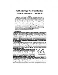
resolutions and the intensity spreading of neighboring pixels onto each other, a simple uniform intensity distribution over the CoC can be used. The algorithms presented by Potmesil and Chen are implemented in software and are far too slow to be applied in near real time. Rokita [13, 14] suggests to use special digital hardware filters to speed up the creation of DOF effects. By multiple consecutive applications of (3x3) Gaussian convolution filters, pixels are spread over their neighboring pixels to create a blurred appearance. Dudkiewicz uses a similar approach applying multiple passes of different sized convolution filters (3x3, 5x5, 7x7) using the SGI RealityEngine2 image processing hardware [6]. The drawback of using convolution filters however, is that they do not allow for a uniform distribution of a pixel’s intensity over the CoC. Furthermore, these filtering techniques give rise to intensity leakage problems, where either blurred foreground or background objects leak into objects that are in focus, or focussed objects leak intensity into blurred background or foreground objects. For all post-filtering techniques it yields that since the image is initially computed from a single point at the center of projection, the intermediate image from which the final DOF image is created does not contain sufficient information to create a perfect DOF image. This affects the results in two ways: First, a real lens’s focusing effect causes light rays that would not pass through the pinhole to strike the lens and to converge to form the image. This leads to undervalued (hypo) pixel intensities at the border of blurred background objects and focussed objects, see figure 3. Second, objects can be partially occluded by other objects in front of them, i.e. they are not ‘visible’ for the entire lens surface. As a result, in post-filtering techniques overvalued (hyper) pixel intensities can occur. Matthews [9] suggests to solve both hypo and hyper intensities by either up or down scaling under and over valued intensities, or by adding or subtracting the pixels original color to obtain a
Figure 3: Hypo intensities. The left object is in focus. The background has been blurred and suffers from too low intensities normalized pixel intensity. Shinya [16] attacks these problems by creating a sub-pixel buffer (the ray distribution buffer) and performing hidden surface removal for each distributed ray. This technique however, adds significant computational and memory costs depending on the accuracy required. Other work regarding fast creation of DOF effects include algorithms developed by Scofield [15] and Fearing [7]. Scofield presents an algorithm where the objects to be rendered are sorted in groups according to their depth, rendered independently into separate images, filtering these images, and finally combining them into the single final image. Fearing proposes an importance ordering method to avoid recalculation of DOF effects in frame sequences with only minor changes. This method however, is not suited for VR applications where major head movements and focus changes occur.
3.2 Multi-Pass Rendering DOF effects can also be created by rendering the scene multiple times with a standard pin-hole camera where the center of projection is slightly translated while preserving a common plane in focus [10]. The final image is generated by accumulation of all the sub-images [8]. A similar 3
technique is used in distributed ray tracing [5, 4]. Here multiple rays are traced through the scene that originate from different locations around the ideal center of projection. Although these techniques produce very good and accurate results, they are computationally ex- Figure 4: Discretized CoC sizes and their borders pensive since the scene has to be rendered multiple times to create a single image. They are therefore age. The RGB values are the original RGB values not suitable for application in VR settings. of the pixels. In the A value however, the pixel’s depth ( 1 ) value is stored. 4 DOF Algorithm Next, the frame buffer is cleared and a number of texture mapped rectangular polygons are The algorithm described here is based on two tech- drawn. The size of the polygons equal the size niques: a high resolution and accurate technique of the original scene, such that each texel covfor the center of attention, and a low accuracy ers exactly one pixel after the polygons are rasterhigh speed approximation for the remaining part ized. First, a polygon is rendered for each pixel in of the scene. Both techniques are based on a post- the outermost front CoC border. The position of processing approach and make extensive use of the polygons is shifted according to the position rendering hardware to obtain high speeds. First, in the CoC border. Only those pixels in the texthe scene is rendered using a standard pinhole tured polygon are rendered that should have a CoC camera. In this intermediate image, each pixel rep- larger than or equal to the diameter of the current resenting an object that should be out of focus has CoC border. This is accomplished by the use of to be spread over its neighboring pixels to create a an alpha test on the alpha value of the texel, i.e. CoC proportional to the CoC that is to be formed the depth value of the original pixel. Furthermore, on the viewer’s retina. by the use of a texture color table lookup function, Each of the techniques is now described in more the alpha values of the pixels to be blended in are detail, followed by an explanation on how these converted to the appropriate intensities. techniques are combined. This process is repeated for the next inner front CoC border, etc., upto the single pixel in the center, after which the pixels in the back CoC border 4.1 High Resolution are done, this time starting with the smallest CoC For this technique, the CoC diameters are dis- border upto the largest. For each border only those cretized to pixel sizes, i.e. CoC’s with diameters of texels are rendered whos CoC contains that pixel. 1, 3, 5, etc. pixels are used. For each of the diame- This selection is easily achieved by performing an ters the CoC border is determined. A CoC border alpha test on the texels’ alpha value, i.e. the pixels is a list of those pixels that ly within this CoC, but depth value. Furthermore, by performing a color are not covered by a CoC of smaller diameter. A table look up operation for the alpha component, pixel is considered to ly within a CoC if its center the correct texel intensity is blended into the scene. lies within the CoC, see figure 4. This process is The blending function used is alpha saturate, and done both for the CoC’s of pixels in front of the in combination with the front to back rendering orfocus plane and behind the focus plane. der this ensures that no hyper-intensity values can An RGBA texture is created from the intermedi- occur. Hypo-intensity values are corrected by a ate image of the same size as the intermediate im- final blend with the original image to normalize 4
struct the next image in the pyramid is applied to the RGBA values of the pixels. The number of levels in each pyramid is determined by the maximum blur needed in the final image. Each image created in one of the pyramids is stored as a 2D texture. Next, the final image is constructed by first rendering texture mapped polygons front to back with the front pyramid textures. Then the pixels of the focus plane are blended in, and finally texture mapped polygons are blended in back to front using the back pyramid textures. The polygons with the pyramid textures are rendered at the appropriate depth coordinates with depth testing enabled such that only those pixels are filled with the blurred texel value that correspond to the amount of blur related to the pixel’s depth value. Linear interpolation over the texel values is enabled to magnify the smaller sized pyramid textures. Finally, the hypo-intensity pixels are corrected by blending in the original image. The main advantages of this technique is that it allows for very fast creation of highly blurred effects. For comparison, a third level pyramid image effectively spreads a pixel over 31x31 pixels. This is achieved with three passes of a 5x5 convolution filter over images that are reduced in size by half in between each filter pass. When such a spread has to be achieved by the technique of Dudkiewicz, 4 consecutive passes of a 7x7 convolution filter have to be applied on the entire image, which is far more expensive.
I2
I1
I0
Figure 5: Gaussian pyramid construction pixels with too low intensities. The main advantages of this technique are that it makes extensive use of fast texturing hardware, all CoCs are created in parallel, and the intensity distributions over the CoCs are uniform. The total number of textured polygons to be rendered and blended in equals the number of pixels in the largest CoC present in the image in front of the focus plane plus the number of pixels covered by the largest CoC behind the focus plane.
4.2 Fast Approximation The fast DOF technique is based on Gaussian pyramids, a technique also used in image coding [2, 1]. Gaussian pyramids offer a very fast way to create low-passed filtered, reduced size representations of an original image. A pyramid is constructed is as follows: From an original image �32 , a reduced or low-pass filtered image � , is constructed. Each value in � , is computed as a weighted average of values in � 2 within a 5 by 5 window. Image �*4 is constructed out of � , in the same manner, etc. Figure 5 illustrates the procedure for a one-dimensional case. For a more detailed discussion on Gaussian pyramids and their use in image coding see [2] and [1]. For the DOF algorithm, two Gaussian pyramids are constructed. The initial image of the first pyramid contains all the pixels closer to the viewer than the focus plane with their alpha value set to 1, all other pixels are cleared. For the second pyramid, all pixels further away than the focus plane are used. The convolution function used to con-
4.3 Combination Each of the two algorithms have their advantages and disadvantages. The first algorithm provides accurate DOF effects, but is somewhat time consuming particularly for larger CoC diameters. Furthermore, the color resolution of the frame buffer imposes a limit on the CoC diameters that can be used; for large CoC diameters pixels have to be blended in with very low intensities. As frame buffers are usually based on integer values, such 5
low intensities do not contribute to the pixel values. The second algorithm provides a very fast way to create DOF effects, especially for larger CoC diameters, but it is of limited accuracy: intensity leakage occurs, the intensity distribution is Gaussian in stead of uniform, and large step sizes in the amount of blur occur. The two techniques however, can be very well combined to obtain a technique that provides accurate DOF effects where it is most needed, yet provides adequate computational speed by applying the fast approximation for those areas where such high accuracy is not necessary. The human visual system is of high resolution in the fovea but into the periphery the resolution rapidly decreases. Furthermore, the larger the CoC’s, the more blurred the scene will be and the less important it becomes to accurately apply DOF effects. Therefore, we combine the two algorithms into one by defining a center of attention volume (CAV) inside the actual viewing volume. This CAV is centered around the object currently focussed at by the viewer. Inside the CAV, we apply the high resolution algorithm, while outside the CAV we apply the fast approximation, see figure 6.
viewing volume Center of Attention Volume
eye point
Figure 6: The Center of Attention Volume (CAV). Inside the CAV the high resolution algorithm is applied, outside the CAV the fast approximation algorithm is applied
5 Results 7698
76
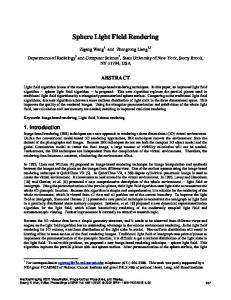
Figure 7 shows a 5 5 image created with the combined algorithm. The image is created on a SGI Onyx with a RealityEngine2 with two raster managers. The scene consists of 3 spheres, with a diameter of 0.14 m located respectively at 0.4, 0.9 and 1.4 m from the viewpoint. Pupil diameter was set to 8 mm and the display screen was 0.4 m away from the viewpoint. The CAV was set to have 5.0 degrees of field of view, and the view was focussed on the green sphere 0.83 m away from the viewpoint. Converting the pinhole camera image of the scene to the final image with DOF cost approxi- Figure 7: Depth of field effects applied to a 3D scene mately 0.24 s. Although this is not yet fast enough to be ap6
plied in todays VR setups, where at least 20 frames per second have to be rendered and preferably even more, it is a significant improvement over other methods while high accuracy is provided in the area where it matters most. For comparison, applying the same DOF effects with the fast algorithm as proposed by Dudkiewicz [6] costs approximately 50 ms. In addition, the final image suffers from intensity leakage.
the convergence-accommodation cue and thus relieving eye strain. If DOF effects are added to such a system, natural vision could be simulated very accurately.
6 Conclusion and Future Work
[2] P.J. Burt and E.H. Adelson. The laplacian pyramid as a compact image code. IEEE Transactions on Communications, 31(4):532–540, 1983.
References [1] P.J. Burt. Fast filter transforms for image processing. Computer Graphics, Image Processing, 6:20–51, 1981.
In VR applications, depth of field not only makes the virtual world look more realistic, but it can also provide an additional depth cue and help in the fusion of stereo images. Applying DOF however, is a costly process. In this paper we have presented a new algorithm that greatly speeds up the application of DOF effects to a scene rendered with a pin-hole camera. The algorithm combines an accurate, high resolution technique for the area on which the viewer is focussed with a faster but less accurate approach for the rest of the scene. It is an improvement over other known algorithms in that it is faster yet provides accurate results where they are most needed. Although not fast enough yet, it brings the application of DOF in VR settings a step closer. A major drawback of current virtual reality display hardware is that the convergenceaccommodation relationship in human viewing is violated. This is a major cause for eye strain often experienced by humans when using VR equipment. It would be an interesting research to investigate whether the application of DOF would have a positive effect in this regard. One step further along this line would be to construct a head-mounted display with a variable focus plane. When equipped with an eye tracking system or a device to measure the power of the lens of the eye, the focus plane of the HMD could be adjusted according to the focus distance of the eye to restore
[3] Y.C. Chen. Lens effect on synthetic image generation based on light particle theory. The Visual Computer, 3(3):125–136, October 1987. [4] R.L. Cook. Stochastic sampling in computer graphics. ACM Transactions on Graphics, 5(1):51–72, 1986. [5] R.L. Cook, T. Porter, and L. Carpenter. Distributed ray tracing. In H. Christiansen, editor, Computer Graphics (SIGGRAPH ’84 Proceedings), volume 18, pages 137–145, 1984. [6] K. Dudkiewicz. Real-time depth-of-field algorithm. In Y. Parker and S. Wilbur, editors, Image Processing for Broadcast and Video Production Proceedings of the European Workshop on Combined Real and Synthetic Imagfe Processing for Broadcast and Video Production, pages 257–268. Springer Verlag, 1994. [7] P. Fearing. Importance ordering for real-time depth of field. In Proceedings of the Third International Conference on Computer Science, pages 372–380, 1996. 7
[8] P. Haeberli and K. Akeley. The accumulation buffer: Hardware support for high-quality rendering. In Forest Baskett, editor, Computer Graphics (SIGGRAPH ’90 Proceedings), pages 309–318, 1990. [9] S.D. Matthews. Analyzing and improving depth-of-field simulation in digital image synthesis. Masters Thesis, University of California, Santa Cruz, December 1998. [10] J. Neider, T. Davis, and M. Woo. OpenGL Programming Guide: The Official Guide to Learning OpenGL. Addison-Wesley, Reading, Mass., first edition, 1993. [11] M. Potmesil and I. Chakravarty. A lens and aperture camera model for synthetic image generation. In H. Fuchs, editor, Computer Graphics (SIGGRAPH ’81 Proceedings), pages 297–305, 1981. [12] M. Potmesil and I. Chakravarty. Synthetic image generation with a lens and aperture camera model. ACM Transactions on Graphics, 1(2):85–108, April 1982. [13] P. Rokita. Fast generation of depth of field effects in computer graphics. Computers & Graphics, 17(5):593–595, 1993. [14] P. Rokita. Generating depth-of-field effects in virtual reality applications. IEEE Computer Graphics and Applications, 16(2):18– 21, March 1996.
6 ,
[15] C. Scofield. 4 Depth of Field Simulation for Computer Animation, volume III of Graphics Gems Series, pages 36–38. AP Professional, 1992. [16] M. Shinya. Post-filtering for depth of field simulation with ray distribution buffer. In Proceedings Graphics Interface ’94, pages 59–66, 1994.
8