it is more efficient to use edge based approaches ... In our target application two major draw backs ... measure, we will use an angle which represents the.
FAST RANGE IMAGE SEGMENTATION FOR INDOOR 3D-SLAM Ahad Harati
Stefan G¨ achter
Roland Siegwart
Autonomous Systems Laboratory Swiss Federal Institute of Technology (ETH Z¨ urich) Tannenstrasse 3, CH-8092 Z¨ urich, Switzerland
Abstract: Real-time 3D localization and mapping is eventually needed in many service robotic applications. Toward a light and practical SLAM algorithm, we focus on feature extraction via segmentation of range images. Using horizontal and vertical traces of the range matrix, 2D observed polygons are considered for calculation of a one-dimensional measure of direction, called Bearing Angle (BA). BA is the incident angle between the laser beam and edges of the observed polygon by the scanner in the selected direction. Based on this measure, two different approaches to range image segmentation, region- and edge-based, are proposed and evaluated through a set of standard analysis. It is experimentally shown that for navigation applications, edge based approaches are more efficient. Extensive tests on real robots prove BA-based segmentation is successful for SLAM.
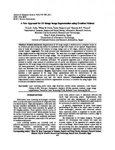
1. INTRODUCTION 3D range scanners are recently getting popularized in mobile robotics. Increasing need for more advanced sensors beside gradual reduction of prices make 3D laser scanners more and more common place in this field. The provided range image is rather rich and precise, hence, these scanners are specially very useful to do Simultaneous Localization and Mapping (SLAM). In order to acquire 3D range data, a nodding 2D laser scanner (Fig. 1) is the simplest setup which is used in various experiments (N¨ uchter et al., 2005; Kohlhepp et al., 2004; Montemerlo and Thrun, 2004). A laser beam is emitted toward the target at constant angular steps in each row, then the whole scanner is tilted. The output is a 2D array of range data which resembles an image with the measured distance as its intensity value in each pixel, called range image (Fig. 1). We will use the mentioned setup mounted on our BIBA robot to acquire range images in order to
do indoor 3D SLAM. In (Nguyen et al., 2006) a simplified practical approach to indoor 2D SLAM is presented. In our current research we pursue extension of this work to 3D. The goal is the development of a simple light algorithm for indoor 3D SLAM useful to service applications. It is apparent that raw data as point clouds is too redundant to be directly used in mapping. For indoor environments planar surfaces are very well suited features which can describe existing major structures like walls, ceiling, floor, cupboards, tables, doors, etc. In this paper, segmentation of range images are studied in order to extract planar surfaces. These planar patches then will be used as features (basic geometric primitives) for implementation of 3D indoor SLAM. Two different approaches to segmentation are proposed based on the introduced 1D orientation measure called Bearing Angle (BA) and extensively tested with range images obtained by our BIBA robot platform. In the first approach, a
a detailed description of various range image segmentation methods can be found in (Jiang and Bunke, 1997).
Fig. 1. Sensor setup: a tilting SICK laser scanner and a sample depth image taken in an office region growing is performed using the extracted lines from each row of range scans. Line extraction based on BA is reported somewhere else (Harati et al., 2006) and here the results are used for segmentation. The second approach directly use BA and perform edge detection. In addition, a simulated office environment is used to compare these two approaches quantitatively. A set of standard analysis is performed on the output of each approach to show how it performs. It is experimentally shown that for navigation applications, it is more efficient to use edge based approaches and BA-based segmentation performs successfully in such domains. We also discuss certain aspect of segmentation that are more critical in navigation.
2. RELATED WORK Range image segmentation is a long standing issue - seminal work addressing this problem has been done by (Besl, 1988). Unfortunately, ready made solutions are rarely available, as it is the case for intensity images, especially when it comes to specific applications such as in 3D SLAM, where robustness, speed, and scalable algorithm are important aspects. For indoor 3D SLAM applications, the range image segmentation should provide consistent features. Such features can be large planar surfaces such as in (Weingarten et al., 2004), since they are easy to observe and parametrize. However, recent research in range image segmentation has focused mostly on the improvement of accuracy and robustness in details of the scene (Han et al., 2004; Wang and Suter, 2004; Gotardo et al., 2003) via increased complexity, which limits the application of such algorithms in mobile robotics. Range image segmentation is a data-driven process that partitions an image into homogeneous patches of maximum size. The segmentation methods follow from the homogeneity criterion and are commonly classified into region and edge based methods. A thorough review of the latest range image segmentation algorithms is missing in the literature, but the evaluation done in (Jiang et al., 2000) is still of current interest. Furthermore,
The region growing algorithm presented in this paper is based on the work of (Jiang and Bunke, 1994), also known as scan-line-grouping. It is a region based approach which treats the range image as collection of scan rows. Each scan row is divided into straight line segments using Splitand-Merge algorithm (Duda and Hart, 1972); then these line segments are merged into 3D-planar surfaces. However, here a less complex line segmentation algorithm is used (Harati et al., 2006). In (Sappa and Devy, 2001) a similar approach is taken which obtains line ends first, but then creates an edge map and process it for labeling. Edge points are linked to each other by applying a graph strategy. In our approach, edge detection is performed on Bearing Angle images and then refined by standard morphological operations. In other work (Bellon and Silva, 2002) standard image processing methods are used. However, they rely on surface normal estimation, which is computationally expensive compared with BA computation. The bearing angle is a 1D measure that characterizes the surface in the selected direction and can be efficiently computed by exploiting the laser scanner geometry. Thus, the algorithms presented in this paper are fast but still can deal with non-uniform sampling of the range images, which is a major difference compared with the cited work.
3. BEARING ANGLE Usually surface normals are estimated to detect change of direction in the scene and segment the range image (Bellon and Silva, 2002; Pulli, 1993). In our target application two major draw backs of surface normals are: complexity of estimation in presence of noise and non-linearity (the elements of surface normal are cosines of the angles which express the patch direction). We will use an alternative measure of direction to overcome these draw backs. To simplify the complexities in dealing with direction estimation, we will take care of each dimension separately. To linearize the measure, we will use an angle which represents the direction. On the other hand, surface normals are often estimated based on neighborhood of each point since small noise on depth information creates a devastating effect on the direction data when just adjacent points are used. Hence, use of filters like Median is quite common as a preprocessing step. However, apart from being time consuming they blur the range image. It will be shown that treating each dimension separately will isolate noise
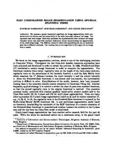
Fig. 2. a. 3D representation of two traces in depth matrix; Green line depicts laser path. b. Zoom of black rectangle in picture a, which shows BA in horizontal and vertical directions. c. Horizontal BA signal calculated in presented row-wise (blue) trace d. Vertical BA signal calculated in presented columnwise (red) trace in different dimensions and leads to enhanced estimation of direction. In fact, using horizontal and vertical traces of the range matrix, range arrays are extracted and utilized to calculate the proposed 1D orientation measure. Noise removal treatments are postponed to the end stage, after applying edge detection and before labeling. To obtain one-dimensional measure of direction, an array of range information is extracted from the depth matrix in desired direction (row, column, diagonal or any other arbitrary trace). The angle between the laser beam and the line passing through each pair of points is called Bearing Angle (BA); see Fig. 2. This angle is calculated for each point in the range array and corresponding array of Bearing Angles gives the desired onedimensional measure through horizontal, vertical or any other selected direction (Fig. 2). More formally: ρi − ρi−1 cos Φi
BAi = arccos q
ρ2i + ρ2i−1 − 2ρi ρi−1 cos Φi
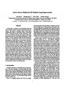
ρi is the ith depth value in the selected trace (extracted array) of the depth matrix and Φi is the corresponding angle increment (laser beam angular step in the direction of the trace). Performing this calculation for all points in the range image and putting BA values in their corresponding row and column will lead to BA image. BA image can be calculated with various traces of depth matrix to highlight relative orientation of the scene in the selected direction. We will show that normally horizontal and vertical traces are enough for a successful segmentation, but any direction can be considered depending on the application, see Fig. 3.
Fig. 3. BA images for a real scan (top right: horizontal, top left: vertical and bottom: two diagonal directions) formed by putting BA values in their corresponding row and column 4. RANGE IMAGE SEGMENTATION To perform segmentation based on the introduced measure, two approaches are compared: a regionbased segmentation using the result of line extraction on each row of the depth image, and an edgebased segmentation. Line-based region growing uses BA-based line extraction (Harati et al., 2006) to first break each scan row into some smooth segments. Since segments are used as seed regions and will be merged to obtain planar surfaces, merging is not performed in line extraction stage. Also no line fitting is necessary, since just the end-point information is used by region growing. The extracted line segments are then merged based on thresholding the distance of the segment endpoints to the growing region. See (G¨achter et al., 2006) for more details. To perform edge-based segmentation, BA images are calculated and processed by an edge detector much like a normal intensity image. In fact BA slightly changes on the smooth regions of the scene. Hence, major changes in BA correspond to the roof edges of the scene. To detect such edges, horizontal and vertical directions are considered separately. Using row and column-wise traces of the range matrix, horizontal and vertical BA images are calculated; see Fig. 3. In addition, depth discontinuities (step edges) in each direction are tagged by thresholding the BA image. When BA is near 0 or 180 degrees, the direction of the environment is nearly parallel to the laser beam; hence, if the range change is beyond the sensor noise, it shows the beam did not hit the target and jumped to the next visible surface. This fact is used to detect the step edges by thresholding the BA image. In our application using horizontal and vertical directions are enough to do a successful segmentation without any smoothing. Outliers in the edge image will be removed by Closing mor-
the structure of the environment and the proposed segmentation method help us to do that. After obtaining the edge image, each closed area gets a label and segmentation is complete.
5. SEGMENTATION PERFORMANCE
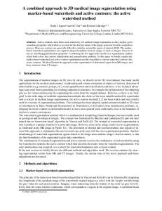
Fig. 4. BA edges for a real scan: a. Horizontal b. Vertical c. combined horizontal and vertical d. After morphological closing phological operation (dilation and then erosion). However, it would be possible to do the same calculation along other directions, as an example BA on two diagonal traces is shown in Fig. 3. When noise level is higher, calculation of BA in other directions may help to detect real edges or close open partially detected edges. Edge detection is applied on each of BA images separately. Final edge image is obtained using logical OR operator on the initial edge images (roof and step edges in each direction). This means any vertical or horizontal edge will be reflected in the final edge image. Using morphological closing it is possible to get rid of some small regions, scattered dots caused by outliers and also to close some incomplete edges. We use closing with a plus shape structuring element (3x3 pixels) for our experiments along with Sobel edge detector (Fig. 4). Closing help us to get rid of small patches also. This is specially very useful in applications like SLAM, since small patches normally come from dynamic objects in the environment. Even if they are not dynamic, their parameters cannot be estimated as robust as major planar surfaces like walls. In fact our main goal in SLAM is to map
Fig. 5. Segmentation output (labeled edge image)
Result of BA based segmentation is carefully analyzed on about 180 range images obtained from crowded offices and corridors in the context of SLAM (Harati and Siegwart, 2007). An example output using edge based approach is depicted in Fig. 5. It can be seen that although because of wide range of scan the scene looks completely deviated in 2D; all major patches are segmented correctly. White area in the right side of the picture, correspond to the windows which are invisible to the laser and tagged as outliers. In addition, to quantitatively compare the two proposed approaches, the performance of each of them is evaluated as described in (Hoover, 1996). However, a different set of range images is used to account for the particularity of the range image sensor. The range images used by (Hoover, 1996) and others are acquired by sensors with a small field-of-view. The images have high density and are almost uniformly sampled on a grid. In contrast, we use a sensor with a large field-ofview. A set of 25 range images are used. They are created by simulation to have access to the ground truth. The images have low density and are uniformly sampled in the angle. Fig. 6 shows a sample scene from the benchmark used for the performance analysis. The performance is measured by comparing the segmentation outcome for simulated range images with the ground truth as described in (Hoover, 1996). Five types of region classification are considered: correct detection, over-segmentation,
(a)
(b)
(c)
(d)
Fig. 6. A sample scene from simulated office: (a) Ground truth segmentation (b) Depth image (c) Output of region based approach (d) Output of edge based approach
Over− and Under−Segmented Instances
Correct Detected Instances 25
50 45
20 Average Classification Rate [%]
40 Average Classification Rate [%]
Over−Segmented (Region) Under−Segmented (Region) Over−Segmented (Edge) Under−Segmented (Edge)
Correct Detected (Region) Correct Detected (Edge)
35 30 25 20 15
15
10
5
10 5 0 50
60
70 80 Classification Threshold [%]
90
100
Fig. 7. Correctly segmented regions (True Positive) under-segmentation, missed, and noise. Oversegmentation results in multiple detections of a single surface. Under-segmentation means insufficient separation of multiple surfaces. A missed classification is used when the segmentation algorithm fails to find a surface, which appears in the image (false negative). A noise classification is used when the segmentation algorithms find a surface, which does not appear in the image (false positive). The classification of segments into these categories are done based on the classification threshold T in the range of (50%, 100%]. The classification threshold measures the congruency between segemented surface and the ground truth. The metrics defining each classification are given in (Hoover, 1996). Fig. 7 shows the ratio of correctly segmented regions. This is rather low, since the simulated scene is very similar to a real office and hence contains a lot of very small surfaces coming from sides of furniture. Therefore, this is not directly comparable with the results reported in (Hoover, 1996), where some artificial polyhedral scene is used. In fact the sample segmented images in Fig. 6
0 50
60
70 80 Classification Threshold [%]
90
100
Fig. 9. Over- and Under-segmented regions clearly show that both approaches are able to correctly segment the major part of the scene corresponding to main structure of the room and big sides of the objects. This is the important issue in SLAM. However, region based approach outperform the edge based approach with few percentage (Fig. 7), since it can find thinner edges between the segments. Logically success rate of the both approaches drops with increase of matching threshold. Again it can be seen that edge based approach reaches zero detection before threshold reaches to 100%, since closing morphological operation makes the edges bold and it never find all the points corresponding to a region. Fig. 8 shows more or less the same fact. For SLAM application, we are not interested in small details of the scene, so the difference of this two approaches in correct detection of small regions can be neglected. To get the correct map of the environment, extraction of the geometry is very critical in SLAM and should be done as precisely as possible. For this reason, under-segmentation is dangerous: it will lead to wrong geometry, but over-segmentation can be dealt with later on by merging patches which come from a same plane. Fig. 9 shows that both approaches are much better regarding the under segmentation.
Missed and Noise Instances 100
As a result, edge based approach is finally selected for SLAM application, since it can segment major part of the scene precise enough to get a good estimate of geometry in a much faster and simpler way.
90
Average Classification Rate [%]
80 70 60 50 40
6. CONCLUSION AND FUTURE WORK
30 Missed (Region) Noise (Region) Missed (Edge) Noise (Edge)
20 10 0 50
60
70 80 Classification Threshold [%]
90
100
Fig. 8. Missed regions (False Negative) and false detected regions (False Positive)
A one-dimensional measure of direction, Bearing Angle, was introduced. Based on this measure, two different approaches to segmentation of range images were proposed and compared: A line-based region growing and an edge based segmentation. Segmentation results are studied through a set of standard analysis and it was reasoned that for
navigation applications, it is more efficient to use edge based approaches and benefit from simple and fast methods. Bearing Angle based segmentation has linear complexity, O(n), regarding the number of points in the range image and is fast enough for navigation purposes. Extensive tests using real range images obtained from our robotic platform proved this approach is successful. We are currently developing SLAM based on the presented segmentation method. Initial results are very satisfying.
ACKNOWLEDGMENT This work has been supported by the Swiss National Science Foundation No 200021-101886 and the EU project Cogniron FP6-IST-002020.
REFERENCES Bellon, O.R.P. and L. Silva (2002). New improvements to range image segmentation by edge detection. Signal Processing Letters, IEEE 9(2), 43–45. Besl, P.J. (1988). Surfaces In Range Image Understanding. Springer-Verlag Inc., New York. Duda, R.O. and P.E. Hart (1972). Pattern Classification and Scene Analysis. Chap. 9, pp. 328– 341. John Wiley & Sons, New York. G¨achter, S., V. Nguyen and R. Siegwart (2006). Results on range image segmentation for service robots. In: Proceedings of the Fourth IEEE International Conference on Computer Vision Systems. Gotardo, P.F.U., O.R.P. Bellon and L. Silva (2003). Range image segmentation by surface extraction using an improved robust estimator. In: Computer Vision and Pattern Recognition, 2003. Proceedings. 2003 IEEE Computer Society Conference on. Vol. 2. pp. II– 33–8. Han, F., Z. Tu and S.-C. Zhu (2004). Range image segmentation by an effective jump-diffusion method. Pattern Analysis and Machine Intelligence, IEEE Transactions on 26(9), 1138– 1153. Harati, A., S. G¨ achter and R. Siegwart (2006). Fast range image segmentation for indoor 3d-slam. Technical Report 166200-2006-01. Swiss Federal Institute of Technology (ETH Z¨ urich). Switzerland. Harati, Ahad and Roland Siegwart (2007). Orthogonal 3D-slam in indoor using right angle corners. In: Submitted to the European Conference on Mobile Robotics. Hoover, A. et al. (1996). An experimental comparison of range image segmentation algorithms. IEEE Transactions on Pattern Analysis and Machine Intelligence 18(7), 673–689.
Jiang, X. and H. Bunke (1994). Fast segmentation of range images into planar regions by scan line grouping. Machine Vision and Applications 7(2), 115–122. Jiang, X. and H. Bunke (1997). Dreidimensionales Computersehen: Gewinnung und Analyse von Tiefenbildern. Springer-Verlag, Berlin und Heidelberg. Jiang, X., K. Bowyer, Y. Morioka, S. Hiura, K. Sato, S. Inokuchi, M. Bock, C. Guerra, R.E. Loke and J.M.H. du Buf (2000). Some further results of experimental comparison of range image segmentation algorithms. In: Proceedings of the 15th International Conference on Pattern Recognition. Kohlhepp, P., P. Pozzo, M. Walther and R. Dillmann (2004). Sequential 3D-SLAM for mobile action planning. In: Intelligent Robots and Systems, 2004. (IROS 2004). Proceedings. 2004 IEEE/RSJ International Conference on. Vol. 1. pp. 722–729. Montemerlo, M. and S. Thrun (2004). A multiresolution pyramid for outdoor robot terrain perception. In: Proceedings of the AAAI National Conference on Artificial Intelligence. AAAI. San Jose, CA. Nguyen, V., A. Harati, N. Tomatis, A. Martinelli and R. Siegwart (2006). Orthogonal SLAM: a step toward lightweight indoor autonomous navigation. In: Proceedings of the IEEE/RSJ Intenational Conference on Intelligent Robots and Systems, IROS. N¨ uchter, A., K. Lingemann, J. Hertzberg and H. Surmann (2005). Heuristic-based laser scan matching for outdoor 6D SLAM. In: Advances in Artificial Intelligence. KI 2005. Proceedings Springer LNAI. 28th Annual German Conference on. Vol. 3698. pp. 304– 319. Pulli, K. (1993). Vision methods for an autonomous machine based on range imaging. Master’s thesis. Licentiate Thesis, ACTA Universitatis Ouluensis, C 72. Sappa, A.D. and M. Devy (2001). Fast range image segmentation by an edge detection strategy. In: 3-D Digital Imaging and Modeling, 2001. Proceedings. Third International Conference on. pp. 292–299. Wang, H. and D. Suter (2004). MDPE: A very robust estimator for model fitting and range image segmentation. International Journal of Computer Vision 59(2), 139–166. Weingarten, J.W., G. Gr¨ uner and R. Siegwart (2004). Probabilistic plane fitting in 3D and an application to robotic mapping. In: Robotics and Automation, 2004. Proceedings. ICRA ’04. 2004 IEEE International Conference on. Vol. 1. pp. 927–932.