ELECTRONICS, VOL. 14, NO. 2, DECEMBER 2010
65
Feed – Forward Based Direct Torque and Flux Control of Induction Motor in Field Weakening Regime Petar Matić, Slobodan N. Vukosavić, and Dejan Raca
Abstract—An original feed-forward stator flux regulator for induction machines is presented in this paper. The regulator is well suited for torque and flux control of induction machines in flux weakening regime, when the only available control variable is stator flux angle. Proposed regulator is analytically described and tested via computer simulation. Index Terms—Induction Motor, Torque Control, Field Weakening.
I
I. INTRODUCTION
NDUCTION motor can operate over a wide speed range, starting from zero speed, to the speed several times higher than the nominal. Operating mode with speeds larger than nominal is called the “field weakening”, because in this regime the flux amplitude is less than nominal. Flux weakening is a natural consequence of voltage limit. There are a number of methods for controlling asynchronous motor in both voltage and current limit, but a satisfactory solution suitable for field weakening has not yet been found [1-10]. A common approach to operate in the field weakening is to simply choose the flux reference inversely proportional to the speed. Such a method does not include the current limit, leading that maximum performance of the drive can’t be achieved. Vector control is based on the assumption of an independent control of flux and torque by using active and magnetizing current components. For the realization of decoupled control, it is necessary to have two degrees of freedom, which is not the case in field weakening due to voltage limit. Therefore, there is a need to deeply explore possible methods to directly control the induction motor in field weakening, and take into consideration the simultaneous current and voltage limits. The method must ensure optimal use of magnetic core of the motor with high-quality dynamic response. The maximum (transient) torque of machine depends on rotor flux squared, and slip. Flux depends on the voltage P. Matić is with the Faculty of Electrical Engineering, Banja Luka, Republic of Srpska, Bosnia and Herzegovina (e-mail:
[email protected]). S. N. Vukosavić is with the Faculty of Electrical Engineering, Belgrade, Serbia (e-mail:
[email protected]). D. Raca is with AMSC Windtec, Klagenfurt, Austria (e-mail:
[email protected]).
limit, slip depends on the current limit, so transient torque depends on both limits. When the machine is fed from an ideal voltage source, then the maximum torque is equal to the break down torque. In this regime, the slip is equal to the break down slip which depends only on the motor parameters (it is constant at all speeds). The effect of voltage limit on transient characteristic is that break down torque in the field weakening decreases with the square of speed, while in the constant flux zone is constant. The maximum torque that can be obtained in the presence of current limit is less than break down torque, and the corresponding slip is then less than break down slip. The influence of the current limit on transient characteristic can be analyzed by comparing the slip in the presence of maximum permissible current with the break down slip. Rotor flux vector control is usually analyzed by assumption of quasi steady states of rotor flux. Current and voltage limits are presented in the d-q frame by circle and ellipse. The torque reference in that frame is represented as parabola, and the working point is found as intersection of the parabola either with circle or ellipse. Therefore, three characteristic regimes can be defined: first, when only the current limit should be observed (constant flux region), the second regime, when both current and voltage limit are observed (this mode corresponds to constant power mode), and finally, the third regime, when only the voltage limit is present. [8-15]. Stator flux vector control is usually simpler in field weakening because it is inherently based on voltage control of the machine. Analysis of operating points is performed in a plane defined by stator flux and torque. In field weakening it is necessary to simultaneously observe voltage and current limits, as well as stability limit. The working point must always be chosen by respecting the stricter requirement. The basic drawback of stator flux vector control is that this approach does not include the dynamics of the rotor circuit. In flux weakening, rotor flux decreases when load is increasing [15-20]. Direct torque control (DTC) performances are superior to vector control. Direct torque control is based on direct control of stator flux and torque, without current regulation, with maintaining the rotor flux at a given value. DTC takes the advantages of rotor flux vector control because it controls
ELECTRONICS, VOL. 14, NO. 2, DECEMBER 2010
66
rotor flux, and the advantages of the stator flux vector control because it uses a direct link between the stator flux and voltage. Drawback of common DTC solutions is that the current and voltage limits are taken into account indirectly, using the motor equations in steady state. In transient regimes stator flux regulator can go into saturation, or it can generate reference voltages larger than nominal voltage [15-20]. Influence of stator resistance is neglected at high speeds, because the voltage drop on it is only a few percent of the motor voltage. The influence of magnetic saturation is such that the voltage limit becomes more stringent when machine is saturated, than in the case of linear magnetic core. Analysis of the influence of magnetic saturation is performed by an approximation of magnetizing curve. When the machine is saturated, the output power at the entering of the field weakening zone may be even greater than the nominal power because the current can be significantly reduced. Saturated machines have a higher power at the same flux and same current limit. In the field weakening mode, a linear magnetic core is usually considered. In this paper a DTC approach, based on full voltage utilization with taking current limit into consideration is presented. First, mathematical model is developed. On the basis of the model, a feed-forward torque control scheme based on voltage angle control is presented. The presented method is verified through computer simulation. II. MATHEMATICAL MODEL
u rk = R r i rk + Ψ sk = L s i sk
∆ Ψ sk ∆T ∆ Ψ rk
∆T + M i rk ,
(8)
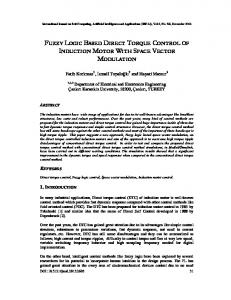
In stationary α − β reference frame, stator flux vectors Ψ sk and Ψ s (k +1) in two adjacent sample periods are shown in
Fig. 1. When
Ψ s (k +1) ≠ Ψ sk , tip of stator flux vector
Ψ s (k +1) is on the circle K 2 , which diameter can be larger or lesser than diameter of circle K1 . When Ψ sk = Ψ s (k +1) , tip of stator flux vector Ψ s (k +1) is on the circle K1 . The angle ∆ϑk between fluxes in two sample periods is also shown in Fig. 1 and in steady state it is equal to the product of synchronous speed and sample time:
∆ϑk0 = ω sk ∆T .
(9) β K2 ψκ+1 ∆ψ
K1 ∆θκ
ψκ
θκ
α
∆Ψ . Stator flux vector increment can be rewritten in form of module and angle as: Fig. 1. Definition of Stator Flux Vector Increment
State-space model of induction motor in stationary reference frame, with fluxes as state variables in discrete time k∆T , k = 0,1,2... is given by following equations:
u sk = R s i sk +
Ψ s (k +1) = Ψ sk + ∆ Ψ sk = Ψ sk + u sk ∆T .
∆ Ψ sk = Ψ s (k +1) (cos ∆ϑk + j sin ∆ϑk ) − Ψ sk ,
(10) (11)
,
(1)
And from (1) stator flux vector increment is: ∆ Ψ sk = u sk ∆T .
+ jω mk Ψ rk ,
(2)
By combining (10) and (11), stator flux vector increment is: (12) ∆ Ψ sk = u sk ∆T [cos(π − ∆χ k ) + j sin (π − ∆χ k )] ,
Ψ rk = Lr i rk + M i sk
(3) (4)
{
}
3 3 m k = P(Ψ sk × i sk ) = − P Im Ψ sk i *sk , (5) 2 2 Where u, i, Ψ are voltage, current and flux vectors, R, L are resistance and inductance, M is mutual inductance, ω m is speed (normalized to one pole pairs), m is torque, P is number of pole pairs. Stator and rotor variables are defined by indexes s, r , and j is imaginary unit. Stator and rotor flux changes during the one sample period k , k = 0,1,2... are defined by: ∆ Ψ sk = Ψ s (k +1) − Ψ sk ,
(6)
∆ Ψ rk = Ψ r (k +1) − Ψ rk .
(7)
Control variable at instant k , k = 0,1,2... is voltage vector u sk . By combining (1) with neglected stator resistance
with (6), the stator flux can be expressed as:
or
s uΨ sk = u sk [cos(π − ∆χ k ) + j sin (π − ∆χ k )] ,
(13)
where ∆χ k is the angle between stator flux increment vector, ∆ Ψ sk , and stator flux vector Ψ sk . The angles ∆ϑk and ∆χ k , s as well as voltage vector u Ψ sk are referred to stator flux vector
Ψ sk . These angles are shown in Fig. 2 β
Ψs(k+1)
∆Ψk εk
∆θk
∆χκ
θk
Ψk
θk Fig. 2. Angle Definitions.
α
s In (13), stator voltage vector, u Ψ sk , which is control
variable, is given by its modulus, u sk , and phase angle ∆χ k
ELECTRONICS, VOL. 14, NO. 2, DECEMBER 2010 referred to the stator flux vector Ψ sk . Stator voltage transformed to the stationary reference frame is: u sk = u sk cos ε k = , (14) = u sk [cos(ϑk + π − ∆χ k ) + j sin (ϑk + π − ∆χ k )]
β
δ Ψk+1
∆Ψβ = Ψ k +1 sin (ϑk + ∆ϑ ) − Ψ k sin ϑk = ∆ Ψ sk sin ε .
Ψ k +1 = Ψ k
flux is kept constant, decreasing
Ψ k +1 < Ψ k .
and when flux is
Angles
for
increasing
are equal to π / 2 , meaning that flux vector increment has only the tangential component. Stator flux regulator is shown in Fig. 5. Inputs to the regulator are stator flux angle advance ∆ϑ , the estimated flux Ψ sk determined by its modules and the appropriate angle,
ε θk
and the sign of the difference between estimated and the reference torque. Outputs are the stator voltage components. The presence of sign of torque variations is necessary to determine the direction of flux change, increase or decrease. This sign is the same as the sign of torque change..
α
TABLE 1 CALCULATION OF ANGLES FROM FIG. 3 AND FIG. 4
Ψ k +1 > Ψ k
π
α β
2
π 2
Ψ k +1 = Ψ k
π
− ∆ϑ
− arcsin
2
Ψ k sin ∆ϑ ∆Ψ k Ψ k sin ∆ϑ
γ
∆ϑ + arcsin
δ
arcsin
ε
ϑk + ∆ϑ + arcsin
∆Ψ k
Ψ k sin ∆ϑ ∆Ψ k
2
π 2
π
Ψ k sin ∆ϑ ∆Ψ k
2
ϑk +
Ψ k +1 < Ψ k
π
− ω k ∆T
ω k ∆T
and
decreasing stator flux are different, and it is necessary to chose appropriate angle γ + or γ − depending on the sign of the flux changes. When stator flux is kept constant, these angles are the same. In case of very small sampling period, i.e., ∆T → 0 , discrete model becomes continuous, and the angles α and γ
Equation (15) is shown in Fig 3 and in Fig. 4 in stationary reference frame for cases of flux increasing and flux decreasing, respectively. Stator flux regulator should produce stator flux vector angle increment ∆ Ψ sk which will guide both torque and flux to their references.
Fig. 3. Stator Flux Vector Increment When Flux is Increasing.
(17)
Table 1 shows all combinations for angles from Fig 3 and Fig 4 for cases when flux is increasing, Ψ k +1 > Ψ k , when
Stator flux regulator can be realized as feed-forward regulator based on stator voltage equation (1) with stator resistance neglected [17]: (15) ∆ Ψ sk = u sk ∆T = Ψ k +1 − Ψ k .
∆θ θk
α
Auxiliary angles α , β and δ shown in Figs 3 and 4 are the same as defined in Fig. 2. Components of stator flux vector increment are found as: ∆Ψα = Ψ k +1 cos(ϑk + ∆ϑ ) − Ψ k cosϑk = ∆ Ψ sk cos ε , (16)
III. STATOR FLUX REGULATOR
α Ψk
θk
Fig. 4. Stator Flux Vector Increment When Flux is Decreasing.
variable is stator flux angle ∆χ k . Inputs to the mathematical model (1-5) are stator and rotor flux vectors, Ψ sk and Ψ rk , and rotor speed ω mk . Mechanical transients are slower than electrical ones, so in the model rotor speed can be assumed to be constant.
β γ
α γ Ψk
∆θ θk
region, its modulus is constant and equal to the rated voltage u sk = U MAX . In field weakening region, the only control
Ψk+1 ∆Ψ δ
β
∆Ψ
In constant flux region, stator voltage modulus is lower than rated voltage, i.e. u sk < U n , while in the field weakening
β
67
ω k ∆T
−
ω k ∆T
π 2
2 2 +
π
+
2
− ∆ϑ
− arcsin
Ψ k sin ∆ϑ ∆Ψ k
π + ∆ϑ − arcsin
arcsin
ω k ∆T 2
2
Ψ k sin ∆ϑ ∆Ψ k
Ψ k sin ∆ϑ ∆Ψ k
ϑk + ∆ϑ + π − arcsin
Ψ k sin ∆ϑ ∆Ψ k
ELECTRONICS, VOL. 14, NO. 2, DECEMBER 2010
68
Fig. 5. Stator Flux Regulator.
IV. BLOCK DIAGRAM OF PROPOSED SOLUTION
controller of the stator flux, which is based on the stator flux angle advance ∆ϑ . Voltage amplitude is determined by the torque reference, synchronous speed and rotor flux (in the first zone), while in the second zone it is limited to maximum available voltage: ⎧ ω s Ls 4 ⎪ Ψr4 + σ 2 L2r me2 u s ≤ u sn 2 (18) u s = ⎨ Ψr Lm 9P ⎪ = u , u u sn s sn ⎩
Proposed solution for field weakening should satisfy the following requirements: a) Torque control should be based solely on the manipulation of the voltage phase angle when its amplitude is maintained at maximum. By this, full use of available inverter voltage is obtained. b) Torque increasing leads to rotor flux decreasing and vice versa, so there is a coupling between torque and flux which is the result of the voltage limit. c) The criterion for entering the field weakening is reaching the maximum available voltage. d) There must be a mechanism to prevent the collapse of the rotor flux because the algorithm is based on manipulation of the stator flux, to fulfill stability condition. Fig. 6. shows the functional block diagram of the proposed direct torque control structure. The structure consists of a torque controller, stator flux controller, block for determining the entering to the field weakening region and the mechanism to prevent the collapse of the rotor flux. All necessary variables are estimated by the torque, and stator and rotor flux amplitude and angle estimator. Torque controller is the PI feed-back controller, which is based on the deviation between torque reference and estimated torque. Another key element of the structure is a feed-forward
m*
PI
Ψr*
Ua
∆θ(k)
uα (k) PWM
+
Us* (k)
Voltage Calculation
*
uα (k) Stator Flux Regulator
1/T
Finally, to prevent rotor flux collapse, which occurs when the slip is larger then break – down slip, there is a structure that stops increasing of the angle when slip becomes equal to the break – down slip. In the constant flux zone, stator voltage will increase when the torque and speed increases. In the field weakening zone the voltage will be kept on the nominal value. As long as the voltage is less than the nominal, there are two control values (voltage angle and amplitude), whereas, when the voltage reaches the nominal value, the only control variable is the voltage angle.
uβ(k) Rs
me (k)E
E
Ψs(k) θs(k) Estimator
E
uβ*(k)
+
Fig. 6. Block-Diagram of the Proposed Solution.
Uc
Rs
E
Ψr(k)
iα (k) iβ (k)
Ub
Sampling & abc-dq
Induction Motor
ELECTRONICS, VOL. 14, NO. 2, DECEMBER 2010
69
Stator flux angle advance ∆ϑ is continuously increasing, as synchronous speed increases. Slip speed is constant in the constant flux region, and is increasing in field weakening region because rotor flux decreases, even the torque is kept constant. Finally, stator voltage increases in the constant flux zone when speed increases, and is kept on the rated value after the machine enters field weakening zone.
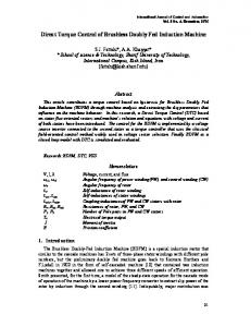
V. SIMULATION RESULTS Simulation of the proposed solution was performed in the program MATLAB – SIMULINK. Motor with rated parameters 7.5 kW, 50Hz, 380V is controlled in torque mode. Reference torque was equal to the 25% of the rated torque, so machine speeds up from standstill to the field weakening zone with constant torque. Simulation results of are shown in Fig. 7 with all variables in per-unit [p.u] values. As it can be seen in Fig. 7, machine torque is constant through the whole simulation period. Stator and rotor fluxes are constant when the speed is below rated value, and are decreased in field weakening region. Torque
Stator Flux 1.5
0.4 1 0.2
0.5
0
0
0.5
1
0
1.5
0
t[s] Rotor Flux
0.5
1 t[s] Stator flux angle dtheta
1.5
1.5 0.04 1
0.02
0.5 0
0 0
0.5
1
-0.02
1.5
0
t[s] Synchronous Speed, Slip Speed, Shaft Speed
0.5
1
1.5
t[s] Stator Voltage 2
4 1
2
0
0
0.5
1
0
1.5
t[s]
0
0.5
1
1.5
t[s]
Fig. 7. Simulation results.
REFERENCES
VI. CONCLUSION The paper proposed a structure for the direct torque and flux control suitable for implementation in the field weakening regime. In field weakening regime there is only one control value, the voltage angle, because the machine voltage amplitude is limited to the nominal value. It is possible only to control torque, while the flux is independently established with respect to voltage limit. Current limit can be satisfied by limiting the slip to the break – down slip. Practical implementation of proposed solution is very complicated due to the parameter sensitivity. The further work on voltage angle control in field weakening should be based on the reconfiguration of the proposed solution to eliminate this parametric sensitivity.
[1] [2] [3] [4]
[5] [6]
[7]
Slobodan N. Vukosavić Digitalno upravljanje električnim pogonima, Akademska Misao, Beograd 2003. Peter Vas: Sensorless Vector and Direct Torque Control, Oxford University Press, London, 1998. Peter Vas Electrical Machines and Drives: A Space-Vector Theory Approach, Oxford University Press, London, 1992. G. Buja, M. Kazmierkowski: “Direct Torque Control of PWM Inverter – Fed AC Motos – A Survey”, IEEE Transactions on Industrial Electronics, Vol. 51, No.4, pp. 744-757, August 2004. Đ. Stojić: „Direktno upravljanje asinhronim motorom“, doktorska disertacija, Univerzitet u Beogradu, 2004. Dj. M. Stojic, S. N. Vukosavic: “A New Induction Motor Drive Based on the Flux Vector Acceleration Method”, IEEE Transactions on Energy Conversion, Vol. 20, No. 1, pp.173-180, March 2005. P. Matić, D. Raca, B. Blanuša, S. N. Vukosavić: “Direct Torque Controlled Induction Motor Drive Based on Double Feedback Structure“, Electronics, Vol. 1, No. 1, pp. 41-48, September/October 2006.
70 [8]
[9]
[10]
[11]
[12]
[13]
[14]
ELECTRONICS, VOL. 14, NO. 2, DECEMBER 2010 N. T. West, R. D. Lorenz: “Implementation and Evaluation of a Stator and Rotor Flux Linkage-Based Dead-Beat, Direct Torque Control of Induction Machines at the Operational Voltage Limits“,The FourtySecond IAS Annual Meeting 2007, Conference Record, pp.690-695, 2327. September 2007. M. Mengoni, L. Yarri, A. Tani, G. Serra, D. Casadei: “Stator Flux Vector Control of Induction Motor Drive in the Field Weakening Region”, IEEE Transactions on Power Electronics, Vol. 23, No. 2, pp. 941-949, March 2008. Jidin, N. Idris, A. Yatim, M. Elbuluk, “ A Novel Overmodulation and Field Weakening Strategy for Direct Torque Control of Induction Machines”, The Fourty-Third IAS Annual Meeting 2007, Conference Record, pp.1-8, 5-9. October 2008. N. Oikonomou, J. Holtz: “Stator Flux Trajectory Tracking Control for High-Performance Drives”, The Fourty-First IAS Annual Meeting 2006, Conference Record, Vol. 3, pp.1268-1275, 8-12. October 2006. M. Mengoni, L. Yarri, A. Tani, G. Serra, D. Casadei: “Stator Flux Vector Control of Induction Motor Drive in the Field Weakening Region”, IEEE Transactions on Power Electronics, Vol. 23, No. 2, pp. 941-949, March 2008. A. Jidin, N. Idris, A. Yatim, M. Elbuluk: “A Novel Overmodulation and Field Weakening Strategy for Direct Torque Control of Induction Machines”, The Fourty-Third IAS Annual Meeting, Conference Record, pp.1-8, 5-9. October 2008. N. T. West, R. D. Lorenz: “Digital Implementation of Stator and Rotor Flux-Linkage Observers and a Stator-Current Observer for Deadbeat
[15]
[16]
[17]
[18]
[19]
[20]
Direct Torque Control of Induction Machines“, IEEE Transactions on Industry Applications, Vol. 45, No. 2, pp. 729-736, March/April 2009. Y. S. Lai, J. H. Chen: “A New Approach to Direct Torque Control of Induction Motor Drives for Constant Inverter Switching Frequency and Torque Ripple Reduction”, IEEE Transactions on Energy Conversion, Vol. 16, No. 3, September 2001. D. Casadei, G. Serra, A. Tani, L. Zarri, F. Profumo: ”Performance Analysis of a Speed Sensorless Induction motor Drive Based on a Constant Switching Frequency DTC Scheme”, IEEE Transactions on Industry Applications, Vol. 39, No. 2, March/April 2003. P. Matić, B. Blanuša, S. N. Vukosavić, “A Novel Direct Torque and Flux Control Algorithm for the Induction Motor Drive”, IEEE International Electric Machines and Drives Conference, IEMDC’03, Proceedings, Vol. 2, pp. 965-970, 1-4. June 2003. Barbara H. Kenny, Robert D. Lorenz: “Stator and Rotor Flux Based Deadbeat Direct Torque Control of Induction Machines”, IEEE Transactions on Industry Applications, Vol 39, No. 4, July/August 2003. C. Lascu, A. Trzynadlowski: “Combining the Principles of Sliding Mode, Direct Torque Control, and Space-Vector Modulation in a HighPerformance Sensorless AC Drive”, IEEE Transactions on Industry Applications, Vol. 40, No. 1, pp. 170-177, January/February 2004. N. T. West, R. D. Lorenz: “Implementation and Evaluation of a Stator and Rotor Flux Linkage-Based Dead-Beat, Direct Torque Control of Induction Machines at the Operational Voltage Limits“,The FourtySecond IAS Annual Meeting 2007, Conference Record, pp.690-695, 2327. September 2007.