1154
IEEE TRANSACTIONS ON INDUSTRIAL INFORMATICS, VOL. 10, NO. 2, MAY 2014
FPGA Implementation of the C-Mantec Neural Network Constructive Algorithm Francisco Ortega-Zamorano, José M. Jerez, and Leonardo Franco, Senior Member, IEEE
Abstract—Competitive majority network trained by error correction (C-Mantec), a recently proposed constructive neural network algorithm that generates very compact architectures with good generalization capabilities, is implemented in a field programmable gate array (FPGA). A clear difference with most of the existing neural network implementations (most of them based on the use of the backpropagation algorithm) is that the C-Mantec automatically generates an adequate neural architecture while the training of the data is performed. All the steps involved in the implementation, including the on-chip learning phase, are fully described and a deep analysis of the results is carried on using the two sets of benchmark problems. The results show a clear increase in the computation speed in comparison to the standard personal computer (PC)-based implementation, demonstrating the usefulness of the intrinsic parallelism of FPGAs in the neurocomputational tasks and the suitability of the hardware version of the C-Mantec algorithm for its application to real-world problems. Index Terms—Circuit complexity, constructive neural networks (CoNN), on-chip learning, threshold networks.
A
I. INTRODUCTION
RTIFICIAL neural networks (ANNs) are the mathematical models inspired in the functioning of the brain that can be utilized in clustering and classification problems, and which have been successfully applied in several fields, including pattern recognition, stock market prediction, control tasks, medical diagnosis, prognosis, etc. Despite years of research in the field of ANN, selecting a proper architecture for a given problem remains a difficult task [1]–[3]. Among the several strategies to solve or alleviate this problem, constructive neural networks (CoNNs) offer the possibility of generating networks that grows as the input data are analyzed, and then they can match the complexity of the set of data [4]. Moreover, the training procedure in CoNN, considered a computationally expensive problem in the standard feedforward neural networks, can be done online and relatively fast. Competitive majority network trained by the error correction (C-Mantec) is a CoNN algorithm recently introduced [5] that implements competition between the neurons permitting them to learn during the whole training process as it does not freeze the synaptic weights
Manuscript received June 24, 2013; revised September 27, 2013; accepted November 29, 2013. Date of publication December 05, 2013; date of current version May 02, 2014. This work was supported in part by Junta de Andalucía under Grant P10-TIC-5770 and Grant P08-TIC-04026, and from CICYT (Spain) under Grant TIN2010-16556 [all include Fondo Europeo de Desarrollo Regional (FEDER) funds]. Paper no. TII-13-0416. The authors are with the Departamento de Lenguajes y Ciencias de la Computación, Universidad de Málaga, Campus de Teatinos S/N, 29071 Málaga, Spain (e-mail:
[email protected]). Color versions of one or more of the figures in this paper are available online at http://ieeexplore.ieee.org. Digital Object Identifier 10.1109/TII.2013.2294137
of the previous incorporated neurons as most CoNN usually do, and also incorporates a built-in filtering scheme to avoid the overfitting problems. These two characteristics permit the algorithm to generate the compact neural architectures with very good generalization capabilities, making the algorithm suitable for its application to devices with limited resources such as microcontrollers, embedded systems, sensor networks, and field programmable gate arrays (FPGAs) [6]. FPGAs are the hardware devices created with the aim of prototyping digital circuits as they offer flexibility and speed. In the recent years, the advancement in technology has permitted to construct FPGAs with a considerable amount of processing power and memory storage, and so they have been applied in several domains (telecommunications, robotics, pattern recognition tasks, infrastructure monitoring, etc.) [7]–[9]. In particular, FPGAs seem quite suitable for neural network implementations as they are intrinsically parallel devices as is the processing of information in neural network models. Several studies have analyzed the implementation of neural networks models in FPGAs [10]–[12]. A broad classification of them can be done according to whether or not they include the learning process on-chip [3], [13]. In the off-chip learning implementations, the training of the neural network model is usually performed in a personal computer (PC), and only the synaptic weights are transmitted to the FPGA that acts as a hardware accelerator [14]–[16]. In contrast, the on-chip learning implementations [17]–[20] permit to train the models autonomously, independently of a PC, consuming much more FPGA resources but offering more flexibility and efficiency. Among the works in this category, we highlight the recent work by Lotrič and Bulic´ [19] where the backprogation algorithm is fully implemented and applied to a large set of benchmark functions, even though there is no significant performance through the use of an FPGA was found in comparison to the software models. An important aspect at the time of the implementation of an algorithm in an FPGA is the data-type representation. The nature of the FPGAs encourages the use of an integer data type, or fixed point representation if a fractional part is needed, because this type of representation is more efficient. A floating point representation might be used but this would require the utilization of specific cores [21], [22]. In this sense, the work of Savich et al. (2007) [23] describes an interesting analysis of the implementation of floating point neural algorithms in the fixed point arithmetic, being the one used in this work. Programming an FPGA is not a trivial task. A straightforward approach would be the use of standard programming languages (C, C++, Fortran, etc.) but unfortunately this option requires the use of language translators that so far tends to be quite inefficient. Instead, FPGAs are predominantly programmed
1551-3203 © 2013 IEEE. Personal use is permitted, but republication/redistribution requires IEEE permission. See http://www.ieee.org/publications_standards/publications/rights/index.html for more information.
ORTEGA-ZAMORANO et al.: FPGA IMPLEMENTATION OF THE C-MANTEC NEURAL NETWORK CONSTRUCTIVE ALGORITHM
using the hardware description languages such as VHDL or Verilog. These languages are complex and thus its programming is usually very time consuming. Furthermore, the existence of several FPGAs manufacturers and a lack of a common standard makes the situation a little bit more complicated [8]. In the present work, we have fully implemented the C-Mantec CoNN model in a VIRTEX-5 XC5VLX110T FPGA but using a general programming approach that may facilitate its portability to other board models. Our aim was twofold: first, to analyze the advantage in processing the speed that can be achieved through the FPGA parallel processing, and second to analyze the actual limitations in the utilization of an FPGA in terms of maximum number of patterns that can be stored, the dimension of the dataset, the differences in using a fixed point representation, etc., and, in particular, analyzing those aspects that arise only when a real hardware implementation is carried on. The organization of the present work is as follows. Section II includes the details about the C-Mantec algorithm. The FPGA implementation is described in Section III, which contains four parts: the first three subsections describe the implementation of the blocks in which the FPGA is divided, and the fourth subsection deals with specific implementation details. Section IV contains the results of testing the implementation on two sets of benchmark functions (Boolean and real-valued problems), together with a detailed comparison of the computational speed between the current FPGA implementation and the original PC-based one. Finally, the paper ends with the discussion of the results and the conclusions obtained. II. C-MANTEC AND CONN ALGORITHM C-Mantec [5] is a novel neural network constructive algorithm that utilizes competition between the neurons and a modified perceptron learning rule (thermal perceptron [24]) to build the single hidden layer compact architectures with good prediction capabilities for the supervised classification problems. As a CoNN algorithm, C-Mantec generates the network topology online during the learning phase, avoiding the complex problem of selecting an adequate neural architecture. The novelty of the C-Mantec in comparison to the previously proposed constructive algorithms is that the neurons in the single hidden layer compete for learning the incoming data, and this process permits the creation of very compact neural architectures. The binary activation state ( ) of the neurons in the hidden layer depends on the input signals , and on the actual value of the synaptic weights ( ) and bias ( ) as follows: on off where
is the synaptic potential of the neuron defined as
In the thermal perceptron rule, the modification of the synaptic is done online (after the presentation of a single weights input pattern) according to the following equation:
1155
where is the target value of the presented input and represents the value of input unit connected to the output by weight . The difference to the standard perceptron learning rule is that the thermal perceptron incorporates the factor. This factor, whose value is computed as shown in (4), depends on the value of the synaptic potential and on an artificially introduced temperature ( )
The value of decreases as the learning process advances according to (5), similarly to a simulated annealing process
where is a cycle counter that defines an iteration of the algorithm on one learning cycle and is the maximum number of iterations allowed. One learning cycle of the algorithm is the process that starts when a chosen pattern is presented to the network and finishes after checking that all neurons respond correctly to the input or when the synaptic weights of the neuron chosen to learn the actual pattern (whether an existing or a new neuron) modifies its synaptic weights. The C-Mantec algorithm has three parameters to be set at the time of starting the learning procedure, and several experiments have shown the robustness of the algorithm that operates fairly well in a wide range of parameter values. The algorithm has the following three parameters. 1) : maximum number of learning iterations allowed for each neuron in one learning cycle. 2) : growing factor that determines when to stop a learning cycle and include a new neuron in the hidden layer. 3) : determines in which case an input example is considered as noise and removed from the training dataset according to the following condition:
where represents an input pattern, is the total number of patterns in the dataset, is the number of times that pattern has been presented to the network on the current learning cycle, and and correspond to the mean and variance of the distribution for all patterns on the number of times where the algorithm has tried to learn each pattern in a learning cycle, respectively. The learning procedure starts with one neuron present in the single hidden layer of the architecture and an output neuron that computes the majority function of the responses of the hidden neurons (a voting scheme). The process continues by presenting an input pattern to the network and if it is misclassified, it will be learned by one of the present neurons whose output did not match the target pattern value if certain conditions are met, otherwise a new neuron will be included in the architecture to learn it. Among all neurons that misclassified the input pattern, the one with the largest will learn it but only if this value is larger than the parameter of the algorithm, a condition included to prevent the
1156
IEEE TRANSACTIONS ON INDUSTRIAL INFORMATICS, VOL. 10, NO. 2, MAY 2014
unlearning of the previous stored information. If no thermal perceptron meeting these criteria is found, a new neuron is added to the network, starting a new learning cycle that includes the resetting of all neurons’ temperature to . Also, at the end of a cycle, the noisy patterns filtering procedure (6) is applied. The algorithm continues its operation iteratively by repeating the previous stages until all patterns in the training set are correctly classified by the network.
MAIN SPECIFICATIONS
TABLE I VIRTEX-5 XC5VLX110T FPGA RELATED AVAILABLE SLICE LOGIC
OF THE
TO ITS
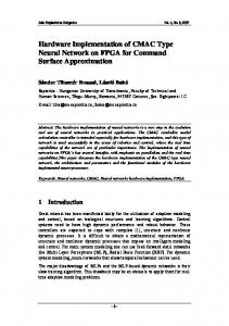
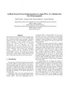
III. FPGA IMPLEMENTATION FPGAs [25] are reprogrammable silicon chips, using prebuilt logic blocks and programmable routing resources. They can be configured to implement the custom hardware functionality, and in this sense, FPGAs are completely reconfigurable and can almost instantly change its behavior by recompiling a new circuitry configuration. The board used for the current implementation is the Virtex-5 OpenSPARC evaluation platform (ML509). This device includes a Xilinx Virtex-5 XC5VLX110T FPGA that provides different connector devices: 2 USB (host and peripheral) ports, 2 PS/2 (keyboard, mouse) ports, RJ-45 (10/100/1000 networking) and RS-232 (male serial port) connectors, 2 Audio inputs (line, microphone), 2 audio outputs (line, Amp, SPDIF), video input, video output (DVI/VGA), and single-ended and differential I/O expansion. Table I shows some characteristics of the Virtex-5 XC5VLX110T FPGA, indicating its main logic resources. A picture of the Virtex-5 OpenSPARC platform is shown in Fig. 1. The VHDL [26], [27] (VHSIC hardware description language) language is used for programming the FPGA, under the “Xilinx ISE Design Suite 12.4” environment using the “ISim M.81d” simulator. VHDL is a hardware description language widely used in the electronic design automation to describe the digital and mixed-signal systems such as FPGAs and integrated circuits, and can also be used as a general purpose parallel programming language. Our design strategy was to avoid the usage of specific Xilinx cores, in order to obtain a general design that can be potentially used in FPGAs from other manufacturers. All computations have been performed using the fixed point arithmetic, which is the standard way to work with FPGA boards. Even if floating point operations can be codified in an FPGA [23], they tend to be more inefficient, as it is also the case for most digital circuits. The implementation of the C-Mantec algorithm in the Virtex 5 FPGA was carried by dividing the board resources in three main blocks. Fig. 2 shows the control, pattern, and neuron blocks created, and the flow of information between them, necessary for the execution of the algorithm. We describe below the organization of each one of the three blocks followed by a subsection that comment on the specific implementations details. A. Neurons Block Each neuron consists of a group of look-up tables (LUTs) containing all information to compute its output ( ), to calculate its value, and to modify its synaptic weights. Neurons receive the information about the input patterns from the pattern
Fig. 1. Picture of a Virtex-5 OpenSPARC platform used for the implementation of the C-Mantec algorithm.
Fig. 2. Scheme of the FPGA design, where the control and pattern blocks are shown together with the neurons.
block and compute their synaptic potential value neuron’s output through the following equation:
to obtain a
on off Note that this equation is similar to the original C-Mantec equation (1) but the inequality condition for activating or not the neuron according to the value of was modified, as now the neuron will be active only if and not in the case . This change permits to compute the majority function of all neurons (the network output) in a much faster way (see control block section). The values of all hidden neurons are sent by the neurons block to the control block for computing the whole network output value that is returned back to the neurons for
ORTEGA-ZAMORANO et al.: FPGA IMPLEMENTATION OF THE C-MANTEC NEURAL NETWORK CONSTRUCTIVE ALGORITHM
deciding whether to compute the values (in case the network output does not match the pattern target value) or to wait for the next input pattern (if network output match the pattern target value), starting the whole process again. In case the network output does not match the target of the current pattern, each neuron computes its value (4), and these values are sent to the control block that will return the information about which neuron has the largest , so this neuron modifies its synaptic weights if its is larger than the value of the parameter . Synaptic weight values are stored in the registers of the FPGA instead of using the RAM block in order to reduce the set-up problems because in this way they are kept close to the neurons. B. Pattern Block Training patterns are managed by the pattern block. Through the serial port pattern, the values are received from the PC and stored in the FPGA distributed RAM block. Patterns are represented using bytes, with the value of determined by the input dimension of the patterns, noting that one extra bit is reserved for the pattern class (the target output). During the execution of the algorithm after a signal from the control block is received, the pattern block sends one randomly selected pattern to all neurons. In order to avoid repeated training of a given pattern, the memory position of the last sent pattern is switched with the one corresponding to the final eligible memory position, whereas the number of eligible memory positions is reduced by 1. This action is repeated until a pattern is found for which the network output is different from its target value, as this case involves modifying the synaptic weights and also the beginning of a new cycle. The C-Mantec algorithm incorporates a filtering scheme for removing patterns considered as “noisy” samples, task also performed by the pattern block. Every time a new neuron is added to the architecture, patterns that needed a number of weight updates larger than the mean plus standard deviation of the whole set of patterns [see (6) and related text] are considered as noise and removed from the training set. In practice, the removal procedure works by storing these “noisy” patterns in the last memory positions. C. Control Block The control block organizes the whole information process by sending and processing the information from the neurons and pattern blocks. Once the patterns have been loaded into the pattern block, the control receives a signal in order to start the execution of the algorithm. The process start by sending a signal to the pattern block indicating that a random chosen pattern should be sent to the neurons. As C-Mantec is a constructive ANN model, the architecture grows as the training phase proceeds, but as FPGA programming needs all elements to be specified before execution, the maximum number of possible neurons in the architecture is created at the beginning with a flag managed by the control block, which determines whether a neuron is activated (included in the actual architecture) or inactivated (waiting for its potential inclusion). At the beginning of the learning process, all synaptic weights are set to zero and the control unit activates only one neuron.
1157
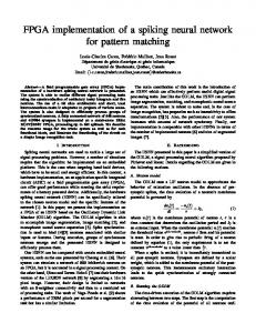
Fig. 3. Functional diagram of the S module for computing the majority function of the hidden neurons outputs.
When a random chosen pattern is sent to the neurons, their outputs ( ) are computed and the control block calculates the majority function of these signals, which is the whole network output in response to the presented input. This output value is compared with the target value and if they match, the control block sends a signal for the release of a new pattern, but if they are different, values are obtained for each of the neurons in order to choose the one with the largest value and in case if its is larger than the value of parameter , start the modification of its synaptic weights. values are received from the neurons and the control unit chooses among the wrong ones, the neuron with the largest . At this point, the control block sends a signal to the chosen neuron so this unit modifies its synaptic weights. The modification of the weights is done serially, updating every synapse according to (3). The control block contains two modules: the and the (Output) modules. The former one calculates the largest of a group of neurons, whereas the module calculates the majority function of the outputs ( ). A detailed description of both the modules is given in the following section. D. Implementation Details 1) Module: This module computes the majority function of the hidden neurons outputs ( ). A diagram showing the schematic operation of this module is shown in Fig. 3. Hidden neurons output ( ) are first added and then this value is compared to the number of active neurons divided by 2, so the majority function can be computed. The output of this module is “1” when the number of activated neurons is larger than the inactivated ones and “0” otherwise. Regarding the logical operation of the circuit, half of the number of active neurons is obtained using a right logical shift operation applied to the number of active neurons. The operation of this module can be performed in just one clock cycle, because computations within this block are not synchronized. 2) Module: This module is in charge of computing the largest value among all neurons whose output does not match the target value for a presented pattern (“wrong” neurons). Since it is more efficient to compute the value among all neurons, we set this value to 0 for the “correct” neurons to obtain the largest value among all (also the value of inactive neurons is set to 0). The highest is calculated in blocks of 16 neurons, as this number was the largest one for which it is not necessary to reduce the operative frequency of the system. If the number of active neurons is larger than 16, the obtained value of the first block is saved and compared to the one obtained from
1158
IEEE TRANSACTIONS ON INDUSTRIAL INFORMATICS, VOL. 10, NO. 2, MAY 2014
TABLE II NUMBER OF LUTS, MAXIMUM OPERATING FREQUENCY, NUMBER OF AVAILABLE NEURONS AND ACCURACY ACCORDING TO THE NUMBER OF BITS USED FOR REPRESENTING THE SYNAPTIC WEIGHTS
Fig. 4. Functional diagram of the module, which calculates the largest value among active neurons and the index of the neuron for which this value was obtained.
the second block, saving the largest value found so far and proceeding in this way until all active neurons are analyzed. Fig. 4 shows an schematic drawing of the procedure used to find the neuron with the largest among those that incorrectly classify the input pattern. This figure shows on its bottom left of the clock signal that synchronizes the module operation. On top of it, values grouped in blocks of 16 that are iteratively sent to the logic circuit that computes the maximum of this block, taking into account the maximum value obtained so far [indicated by in the figure]. After all blocks are analyzed, the module outputs the maximum value found (Max ) together with a value (Index) that indicates the neuron for which this value was found. 3) Product Implementation: The execution of the algorithm requires the computation of several products, such as the computation of the values, the obtention of the synaptic weights, and the neuron potential ( ). In particular, the computation of the value requires three multiplications; one related to the calculation of , another for the interpolation of the exponential function, and the last for obtaining its final value [cf. (4)]. Every neuron has only one multiplier block that is used in a time-division multiplexing scheme to minimize the LUTs’ usage. Xilinx specific multiplication cores are not used because we have decided to use the exportable code, allowing its potential application to other FPGAs. The multiplication block is based on the use of shifters and adders, following the approach introduced in [28]. The number of LUTs required in this scheme is proportional to the bit size of the input data, e.g., for two vectors with and bits length, respectively, the product requires LUTs, whereas the output has a size of bits. 4) Synaptic Weights Precision: The representation of the synaptic weights can be chosen according to the available resources, taking into account that obtaining a higher accuracy may require a larger representation, which will imply an increase in the number of LUTs per neuron (consequently a reduced number of available neurons) and a decrease in the maximum operation frequency of the board. Synaptic weight accuracy is important so that the resulting values are similar to those obtained using the floating point representation used in the PC-based code. A synaptic weight is represented by a bit array with integer and fractional parts of lengths and . determines the minimum and maximum values that can be obtained as to , whereas defines the accuracy . The number of bits needed to
and
indicate the integer and fractional parts of the representation.
TABLE III LUTS PER NEURON, NUMBER OF RAM BLOCKS USED, MAXIMUM NUMBER OF PATTERNS AND NUMBER OF LUTS AND REGISTERS USED IN THE PATTERN BLOCK AS A FUNCTION OF THE INPUT SIZE
represent all possible discrete values within a certain range of positive values depends on the difference between the maximum and minimum values of the interval, and can be obtained from the following equation:
Table II shows the number of LUTs, maximum operating frequency, number of available neurons, and accuracy according to the number of bits used for representing the synaptic weights , where and indicate the integer and fractional parts of the representation, respectively. 5) Number of Inputs: The number of inputs in a C-Mantec network is determined by the dimension of the training patterns. The input dimension strongly influences the whole FPGA implementation as it essentially modifies the number of LUTs per neuron and the maximum number of training patterns that can be stored in the memory board. Further, changing the number of inputs involves a complete modification of the programming code, and in this sense, our approach was to develop different codes according to the maximum number of inputs needed. Of course, one nonoptimal option is to choose the largest input code for all cases, clearly reducing other capabilities of the board. Table III shows the number of LUTs per neuron, the number of RAM blocks used every 1024 patterns, the maximum number of patterns that can be stored ( RAM blocks), and the number of LUTs and registers of the pattern block, all as a function of the number of inputs. The size of the inputs shown in the table corresponds to values of a power of 2 minus 1, as the remaining input is used for the output class. 6) Exponential Function: The calculation of the value involves the computation of an exponential functions involving a negative number. As there is no floating point operations defined in the FPGA, integer fixed point arithmetic should be used. For the exponential function, a table was created that contains the value of the function for some selected inputs.
ORTEGA-ZAMORANO et al.: FPGA IMPLEMENTATION OF THE C-MANTEC NEURAL NETWORK CONSTRUCTIVE ALGORITHM
1159
TABLE IV MEAN AND STANDARD DEVIATION OF THE NUMBER OF NEURONS IN THE GENERATED ARCHITECTURES AND THE TIME (IN SECONDS) NEEDED BY THE ALGORITHM FOR A SET OF 16 BOOLEAN FUNCTIONS, BOTH FOR FPGA AND PC IMPLEMENTATIONS
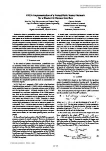
Fig. 5. Exponential function and approximated value (top graph). Absolute (middle) and relative errors (bottom) committed in the approximation of the exponential function (see text for more details).
Storing the table values requires large amounts of memory, and as one table per neuron is needed, only selected input values were stored, and thus the table was built with 64 values starting from 0 down to with 0.125 decreasing steps (values lower than were set to 0). To increase the precision of the exponential calculation, a linear interpolation procedure was implemented. Fig. 5 (top) plots the real, table, and interpolated values for the exponential function, where the inset plot shows an enlargement of a portion of the curve. Fig. 5 (middle and bottom graphs) shows the absolute and relative errors of the exponential function in the range from 0.0 to . 7) : This value, which determines the maximum number of learning modifications that a neuron can suffer in a learning cycle, has been modified with respect to the original C-Mantec code. As this value is employed for calculating the temperature ( ) value, through a division operation with a high associated computational cost, was limited power of 2 values, allowing a conversion of the division operation in a right logical shift. The maximum allowed value of is . IV. RESULTS Different comparisons have been performed between the implementation in VHDL for the selected FPGA and the implementation of the C-Mantec algorithm in C programming language [29], noting that this language is considered among the fastest that can be used in a PC [30]–[32]. The CPU used for
running the C code is an Intel (R) core (TM) Quad CPU Q6600 @ 2.4 GHz. A set of 16 single output Boolean functions was used to test the speed and the architectures generated by the C-Mantec algorithm. The functions used for the tests comprises two sets of arithmetic logic unit (ALU) functions that include 6 Alu2 functions of 10 inputs and 8 Alu4 functions of 14 inputs, both from the MCNC (Microelectronics Center of North Carolina) benchmark [33], together with the exclusive disjunction function (XOR) of two and three inputs. The C-Mantec algorithm was run with the following parameter values: and . (No noise elimination step was applied in this case, i.e., .) Also, a phase-locked loop (PLL) block has been used to set the frequency of the system to 72.72 MHz for all tests. Table IV shows the number of neurons and time (s) needed by the VHDL–FPGA and the C-PC implementations, computed as the mean over 20 simulations run for each function [the standard deviation ( ) is also shown]. A comparison of the learning times is displayed in Fig. 6 using a logarithmic -axis. All the results shown in Table IV were obtained using a 16-bit fixed point representation for the synaptic weights ( ), except the values for function Alu4r for which a larger representation was needed ( ) in order to avoid the saturation effects. We have also computed the time (s) that the system employs for three important tasks involved in a learning cycle: computing the majority function of the hidden neurons’ responses, determining the largest value, and modifying the synaptic weights. For obtaining the majority function, the system needs cycles, for determining the largest , and for modifying the synaptic weights cycles ( is the number of inputs and is the number of neurons). Fig. 7 shows a graphical representation of the running times for the values of and . We further computed the execution times related to the addition of a new neuron as the constructive network grows, comparing the times needed by the FPGA and PC-based implementations using the 10-input function alu2l (30 repetitions
1160
IEEE TRANSACTIONS ON INDUSTRIAL INFORMATICS, VOL. 10, NO. 2, MAY 2014
Fig. 6. Mean and standard deviation of the learning times (in seconds, logarithmic scale) for a set of 16 Boolean functions for VHDL–FPGA and C-PC implementations of the C-Mantec algorithm (these values are also represented in Table IV).
Fig. 8. Execution times needed by the FPGA and PC implementations of C-Mantec related to the addition of a new neuron. Absolute times (top graph) and relative times (bottom graph) computed for the alu2l function (see the text for more details).
Fig. 7. Run time of computing the majority function, determining the largest and modifying the synaptic weights in a learning cycle (see text for more details).
RESULTS
VERSION
were performed in order to obtain an average value). Fig. 8 (top) shows the time needed by the FPGA and PC implementation, whereas Fig. 8 (bottom) shows the relative speed increase between the two platforms. The two curves in Fig. 8 (bottom) corresponds to the relative time needed by the algorithm to achieve the shown number of neurons (cumulative), whereas the upper curve (per neuron) corresponds to the comparison when the algorithm is executed with a constant number of neurons. The cumulative comparison clearly shows that the relative performance of the FPGA (in comparison to the PC implementation) increases almost linearly as the number of neurons in the architecture increases. In another experiment, we analyzed the implementation of real-world functions, using a set of eight binary output benchmark problems from the UCI1 repository. Table V shows the results for the FPGA and PC implementations of the C-Mantec algorithm. The first two columns of the table show the name and number of inputs of the used benchmark problems. The third and fourth columns show the number of neurons obtained for both the implementations, and in the last two columns the generalization ability is shown for both the approaches. The generalization ability was computed using a 10-fold training/test scheme with the following parameters for the C-Mantec algorithm: ( , , ). 1
www.ics.uci.edu/ mlearn/.
TABLE V EIGHT BENCHMARK PROBLEMS IN THE C-MANTEC ALGORITHM
OF THE IMPLEMENTATION OF OF
THE
FPGA
The first two columns show name and number of inputs of the function and the rest of the columns shows the number of neurons and the generalization ability obtained with both platforms.
V. DISCUSSION
AND
CONCLUSION
We have presented and analyzed in this work an FPGA on-chip learning implementation of the recently introduced C-Mantec neural network constructive algorithm. One of the main advantages of using this new algorithm is the fact that in comparison to backpropagation training (the standard choice in the ANN field) it avoids the problem of selecting the adequate architecture, as this process is done automatically according to the complexity of the input data. A further advantage of C-Mantec is its robustness regarding the parameter settings [5]. Several tests carried on two well-known benchmark datasets (cf. Tables IVand V) show that the fixed precision representation
ORTEGA-ZAMORANO et al.: FPGA IMPLEMENTATION OF THE C-MANTEC NEURAL NETWORK CONSTRUCTIVE ALGORITHM
used (16 bits fixed point) for most cases is enough to achieve the results comparable to the floating point original PC-based execution of the algorithm, as almost indistinguishable results were obtained for the size of the generated architectures and for the generalization ability of the algorithm. Regarding the advantage of using the FPGA version of the algorithm instead of standard software, a clear significant speed increase has been observed, noting that this increase grows approximately linear as the complexity of the problem augments (cf. Fig. 7 bottom graph), thus obtaining a factor increase of up to 47 times in the case of the most complex function analyzed (function Alu4r in Table IV). In the light of the observed results, we can conclude that the present analysis demonstrates the suitability of the C-Mantec algorithm for its application in the real-world industrial problems in which FPGAs are commonly used [34], such as industrial motor control [35], machine vision [36], industrial networking [37], robotics [38], etc. Further, the experiments carried out confirm the great potential that FPGAs have for neurocomputational tasks given its intrinsic parallel processing. ACKNOWLEDGMENTS The authors would like to acknowledge P. Monasterio-Huelin, A. I. Molina, and M. González for fruitful discussions. REFERENCES [1] I. Gómez, L. Franco, and J. Jerez, “Neural network architecture selection: Can function complexity help?,” Neural Process. Lett., vol. 30, pp. 71–87, 2009. [2] D. Hunter, Y. Hao, M. Pukish, J. Kolbusz, and B. Wilamowski, “Selection of proper neural network sizes and architectures—A comparative study,” IEEE Trans. Ind. Appl., vol. 8, no. 2, pp. 228–240, May 2012. [3] K. Lakshmi and M. Subadra, “A survey on FPGA based MLP realization for on-chip learning,” Int. J. Sci. Eng. Res., vol. 4, 2013. [4] L. Franco, D. Elizondo, and J. Jerez, Constructive Neural Networks, Berlin, Germany: Springer-Verlag, 2009. [5] J. Subirats, L. Franco, and J. Jerez, “C-Mantec: A novel constructive neural network algorithm incorporating competition between neurons,” Neural Netw., vol. 26, pp. 130–140, 2012. [6] D. Urda, E. Canete, J. L. Subirats, L. Franco, L. Llopis, and J. M. Jerez, “Energy-efficient reprogramming in WSN using constructive neural networks,” Int. J. Innov. Comput. Inf. Control, vol. 8, pp. 7561–7578, 2012. [7] E. Monmasson, L. Idkhajine, M. Cirstea, I. Bahri, A. Tisan, and M. W. Naouar, “FPGAs in industrial control applications,” IEEE Trans. Ind. Informat., vol. 7, no. 2, pp. 224–243, May 2011. [8] D. Bacon, R. Rabbah, and S. Shukla, “FPGA programming for the masses,” Queue, vol. 11, pp. 40–52, 2013. [9] P. Conmy and I. Bate, “Component-based safety analysis of FPGAs,” IEEE Trans. Ind. Informat., vol. 6, no. 2, pp. 195–205, May 2010. [10] J. Zhu and P. Sutton, “FPGA implementations of neural networks—A survey of a decade of progress,” Lecture Notes Comput. Sci., vol. 22778, pp. 1062–1066, 2003. [11] A. Gomperts, A. Ukil, and F. Zurfluh, “Development and implementation of parameterized FPGA-based general purpose neural networks for online applications,” IEEE Trans. Ind. Informat., vol. 7, no. 1, pp. 78–89, Feb. 2011. [12] Q. Le and J. Jeon, “Neural-network-based low-speed-damping controller for stepper motor with an FPGA,” IEEE Trans. Ind. Appl., vol. 57, no. 9, pp. 3167–3180, Sep. 2010. [13] A. Omondi and J. Rajapakse, FPGA Implementations of Neural Networks, New York, NY, USA: Springer, 2006. [14] S. Himavathi, D. Anitha, and A. Muthuramalingam, “Feedforward neural network implementation in FPGA using layer multiplexing for effective resource utilization,” IEEE Trans. Neural Netw., vol. 18, no. 3, pp. 880–888, May 2007.
1161
[15] S. Jung and S. S. Kim, “Hardware implementation of a real-time neural network controller with a DSP and an FPGA for nonlinear systems,” IEEE Trans. Ind. Electron., vol. 54, no. 1, pp. 265–271, Feb. 2007. [16] T. Orlowska-Kowalska and M. Kaminski, “FPGA implementation of the multilayer neural network for the speed estimation of the two-mass drive system,” IEEE Trans. Ind. Informat., vol. 7, no. 3, pp. 436–445, Aug. 2011. [17] A. Dinu, M. Cirstea, and S. E. Cirstea, “Direct neural-network hardwareimplementation algorithm,” IEEE Trans. Ind. Electron., vol. 57, no. 5, pp. 1845–1848, May 2010. [18] A. Gomperts, A. Ukil, and F. Zurfluh, “Implementation of neural network on parameterized FPGA,” in Proc. AAAI Spring Symp.: Embedded Reasoning, Stanford, CA, USA, 2010. [19] U. Lotrič and P. Bulic´, “Applicability of approximate multipliers in hardware neural networks,” Neurocomputing, vol. 96, pp. 57–65, 2012. [20] J. Shawash and D. Selviah, “Real-time nonlinear parameter estimation using the Levenberg-Marquardt algorithm on field programmable gate arrays,” IEEE Trans. Ind. Electron., vol. 60, no. 1, pp. 170–176, Jan. 2013. [21] C. H. Ho, C. W. Yu, P. Leong, W. Luk, and S. J. E. Wilton, “Floating-point FPGA: Architecture and modeling,” IEEE Trans. Very Large Scale Integr. (VLSI) Syst., vol. 17, no. 12, pp. 1709–1718, Dec. 2009. [22] Z. Jovanovic and V. Milutinovic, “FPGA accelerator for floating-point matrix multiplication,” IET Comput. Digit. Technol., vol. 6, no. 4, pp. 249–256, 2012. [23] A. W. Savich, M. Moussa, and S. Areibi, “The impact of arithmetic representation on implementing MLP-BP on FPGAs: A study,” IEEE Trans. Neural Netw., vol. 18, no. 1, pp. 240–252, Jan. 2007. [24] M. Frean, “The upstart algorithm: A method for constructing and training feedforward neural networks,” Neural Comput., vol. 2, no. 2, pp. 198–209, Apr. 1990. [25] S. Kilts, Advanced FPGA Design: Architecture, Implementation, and Optimization, Hoboken, NJ, USA: Wiley, 2007. [26] P. Ashenden, The Designer’s Guide to VHDL, Vol. 3, (Systems on Silicon), 3rd ed., Burlington, MA, USA: Morgan Kaufmann Publishers, 2008. [27] P. P. Chu, FPGA Prototyping by VHDL Examples: Xilinx Spartan-3 Version, Hoboken, NJ, USA: Wiley, 2008. [28] P. P. Chu, RTL Hardware Design Using VHDL: Coding for Efficiency, Portability, and Scalability, Hoboken, NJ, USA: Wiley, 2006. [29] D. M. Ritchie, “The development of the C language,” Proc. 2nd ACM SIGPLAN Conf. History Program. Lang, ser. HOPL-II, New York, NY, USA: ACM, 1993, pp. 201–208. [30] B. Fulgham, “The computer language benchmarks game” [Online]. Available: http://benchmarksgame.alioth.debian.org/ Last accessed on Dec. 27, 2013. [31] Bioinformatics.org, “Language benchmark” [Online]. Available: http:// www.bioinformatics.org/benchmark/results.html Last accessed on Dec. 27, 2013. [32] R. Hundt, (2011). “Loop recognition in C++/java/go/scala,” in Proc. Scala Days 2011 [Online]. Available: https://days2011.scala-lang.org/sites/ days2011/files/ws3-1-Hundt.pdf. [33] ACM/SIGDA benchmarks [Online]. Available: http://www.cbl.ncsu. edu:16080/benchmarks/. [34] Y. Lin, Using FPGAs to Solve Challenges in Industrial Applications, WP410 (V2.0), Xilinx, Oct. 2012. [35] S. Maiti, V. Verma, C. Chakraborty, and Y. Hori, “An adaptive speed sensorless induction motor drive with artificial neural network for stability enhancement,” IEEE Trans. Ind. Informat., vol. 8, no. 4, pp. 757–766, Nov. 2012. [36] D. Kim, T. Nguyen, M. Kim, and J. Jeon, “Design and implementation of a pipelined datapath for high-speed face detection using FPGA,” IEEE Trans. Ind. Informat., vol. 8, no. 1, pp. 158–167, Feb. 2012. [37] P. Ferrari, A. Flammini, D. Marioli, and A. Taroni, “A distributed instrument for performance analysis of real-time ethernet networks,” IEEE Trans. Ind. Informat., vol. 4, no. 1, pp. 16–25, Feb. 2008. [38] X. Shao and D. Sun, “Development of a new robot controller architecture with FPGA-based IC design for improved high-speed performance,” IEEE Trans. Ind. Informat., vol. 3, no. 4, pp. 312–321, Nov. 2007. Francisco Ortega-Zamorano, photograph and biography not available at time of publication. José M. Jerez, photograph and biography not available at time of publication. Leonardo Franco (M’06–SM’13), photograph and biography not available at time of publication.