Generating Nearly Optimally Compact Models from. Krylov-Subspace Based Reduced-Order Models. Matt Kamon, Frank Wang, and Jacob White, Member, IEEE.
IEEE TRANSACTIONS ON CIRCUITS AND SYSTEMS—II: ANALOG AND DIGITAL SIGNAL PROCESSING, VOL. 47, NO. 4, APRIL 2000
239
Generating Nearly Optimally Compact Models from Krylov-Subspace Based Reduced-Order Models Matt Kamon, Frank Wang, and Jacob White, Member, IEEE
Abstract—Automatic model reduction of chip, package, and board interconnect is now typically accomplished using moment-matching techniques, where the matching procedure is computed in a stable way using orthogonalized or biorthogonalized Krylov-subspace methods. Such methods are quite robust and reasonably efficient, though they can produce reduced-order models that are far from optimally accurate. In particular, when moment-matching methods are applied to generating a reduced-order model for interconnect which exhibits skin effects, the generated models have many more states than necessary. In this paper, we describe our two-step strategy in which we first compute medium-order models using an efficient moment-matching method, and then nearly optimally reduce the medium-order models using truncated balanced realization. Results on a spiral inductor and a package example demonstrate the effectiveness of the two-step approach. Index Terms— Frequency dependence, interconnect, modelorder reduction, packaging, parasitics.
I. INTRODUCTION
A
S GIGAHERTZ frequencies become more common in both digital and analog integrated circuits and systems, designers have required more accurate and wider band models of packaging parasitics and distributed components like spiral inductors. For example, gigahertz-plus operating frequencies often generate unexpected loss in conductors due to current crowding near conductor surfaces. For this reason, models of packages and spiral inductors must include this current-crowding, or skin, effect [1]. However, since many of these models are typically combined with hundreds of transistors to perform circuit-level simulation of an entire subsystem, the models of these distributed components must achieve accuracy without being too expensive to evaluate. One standard approach to generating accurate wideband models of packaging parasitics or distributed components is to use a three-dimensional (3-D) electromagnetic analysis program to compute frequency-dependent impedences or S-parameters. Then, the frequency response can be converted to an impulse response using the inverse Fourier transform. When such generated impulse responses are used in a circuit simulation program, they are convolved with other circuit waveforms to generate appropriate currents and voltages [2], Manuscript received January 21, 1999; revised September 3, 1999. This work was supported by DARPA Composite CAD program and by a Grant from SRC. This paper was recommended by Associate Editor M. Nakhla. M. Kamon is with Microcosm Technologies, Inc., Cambridge, MA 02142 USA. F. Wang and J. White are with the Massachusetts Institute of Technology, Cambridge, MA 02139 USA. Publisher Item Identifier S 1057-7130(00)03132-3.
[3]. The difficulty with convolution-based approaches is that the models are expensive to construct because the electromagnetic behavior must be analyzed at many frequencies, and the models are expensive to use because the cost of convolution grows with the square of the number of timepoints in the circuit simulation. It is possible to improve the convolution approach described above by using rational function fitting instead of the inverse Fourier transform [4], [5]. However, when magnetoquasistatic (RL) analysis is sufficient, it is more efficient to generate reduced-order state-space models directly from a PEEC-based [6] magnetoquasistatic simulator [7]. These state–space models, generated using numerically robust orthogonalized Krylov-subspace based methods [8]–[12], can be carried out to a sufficiently high order to ensure capturing all the important frequency-dependent effects. For problems that exhibit significant skin effect, it has been observed that Krylov-subspace based model order reduction applied to PEEC-based magnetoquasistatic analysis must be carried out to high order to capture these skin effects [13]. Such a result is disappointing, because the resulting reduced-order model is expensive to evaluate. In addition, the need for a highorder model is surprising, since the change in impedance due to skin effect is very smooth and one would expect that a low-order state–space model should be sufficient. For these reasons, several researchers have been examining the near optimal model order reduction methods discussed extensively in the control literature. These methods, based on truncated balanced realizations (TBR) [14], produce reduced-order models that are near optimally accurate. TBR methods are not commonly used for reduction from three-dimensional simulation because the computational cost grows cubically with the original system’s size. Finding an approach that retains the computational efficiency of Krylov-subspace based methods with the accuracy of TBR methods has been a topic of much recent research [15]–[17]. For the problem of magnetoquasistatic analysis, the methods in [15], [16] are nearly equivalent to first reducing the extremely highorder ( 10 000) system generated by PEEC discretization to a high-order ( 100) reduced-order model. Then, TBR methods are used to further reduce the model to one with fewer than ten states. In this paper, we show that the two-step method is particularly efficient for magnetoquasistatic problems that exhibit skin effect. We begin in Section II by describing the mesh formulated PEEC approach to modeling 3-D interconnect. Then, in Section II-B, we review using the PRIMA algorithm to generate reduced models and demonstrate the large size models needed to capture skin and proximity effects. Then in Section III, we introduce TBR and show how the PRIMA models can be compacted.
1057–7130/00$10.00 © 2000 IEEE
240
IEEE TRANSACTIONS ON CIRCUITS AND SYSTEMS—II: ANALOG AND DIGITAL SIGNAL PROCESSING, VOL. 47, NO. 4, APRIL 2000
Fig. 1. One conductor: (a) as piecewise-straight sections, (b) discretized into filaments, and (c) modeled as a circuit.
A. The Mesh-Formulation Approach
Fig. 2. Discretization to model a thin plane. Segments are one-third actual width for illustration.
Section IV shows two examples of compact model generation, and in Section V, we conclude and describe future work.
II. BACKGROUND To begin, we review generating an equivalent circuit for resistance and inductance computation from the magnetoquasistatic Maxwell equations via the mesh-formulated PEEC approach. Then in Section II-B, we describe reducing that equivalent circuit via PRIMA.
The frequency-dependent resistance and inductance matrices describing the terminal behavior of a set of conductors can be rapidly computed with the multipole-accelerated mesh-formulated PEEC approach as implemented in FASTHENRY [18]. To model current flow in the PEEC method, the interior of conductors is divided into volume filaments, each of which carries a constant current density along its length. In order to capture skin and proximity effects, the cross section of each conductor is divided into bundles of filaments. The interconnection of the filaments, plus sources, at the terminal pairs, generates a “circuit” whose solution gives the desired inductance and resistance parameters. These concepts are illustrated in Fig. 1, where a single bent wire is divided into sections and those sections are each divided into a bundle of filaments. In the figure, each section is divided into four filaments, but in practice they are divided into many more, with thin filaments near the surface to capture the concentration of current there at high frequencies due to the skin effect. To model two-dimensional (2-D) and 3-D current distributions, the filaments can be connected into a grid, as shown for a thin plane in Fig. 2. To derive a system of equations for the filament currents, we start by assuming the system is in sinusoidal steady-state, and following the partial inductance approach in [19], the branch current phasors can be related to branch voltage phasors by
(1)
KAMON et al.: GENERATING NEARLY OPTIMALLY COMPACT MODELS
241
where is the number of branches (number of is the complex impedance current filaments), and matrix given by
solves. Instead, consider automatically reducing the size of (4) via PRIMA, as described in Section III-B. B. Model-Order Reduction with PRIMA
(2) where is the excitation frequency. The entries of the diagonal represent the dc resistance of each current filmatrix is the dense matrix of partial inductances ament, and [20]. The partial inductance matrix is dense since every filament is magnetically coupled to every other filament in the problem. To apply the circuit analysis technique known as mesh analysis we explicitly enforce Kirchhoff’s voltage law, which implies that the sum of branch voltages around each mesh in the network is zero (a mesh is any loop of branches in the graph which does not enclose any other branches). This relation is represented by (3) is the mostly zero vector of source branch voltwhere is the vector of mesh currents, and ages, is the mesh matrix. Here, is the number of meshes, which is typically somewhat less than , the number of filaments. Combining (3) and (1) yields (4) The complex admittance matrix which describes the external , terminal behavior of a -conductor system, denoted can by derived from (4) by noting that (5) and are the terminal source currents and voltages of the -conductor system ( and of Fig. 1), which are related , where to the mesh quantities by is a terminal incidence matrix determined by the mesh formulation. At this point, it would be possible to insert the equivalent circuit of the multiconductor system directly into a circuit simulator for time domain simulation with nonlinear devices. However, to capture skin effect, the number of filaments, , can exceed 10 000. Factoring such a dense matrix at just one simuoperations, and would take hours lator time step requires of CPU time and nearly a gigabyte of memory. Instead, recently developed methods replace the original system with a reduced-order model with nearly the same admittance characteristics. One approach to generating a reduced-order model would be to solve (4) at many frequency points and then fit this data to a rational function [21]. To make the single frequency analyses reasonably efficient, (4) should not be solved by Gaussian , elimination, whose computational cost grows like but instead be solved using accelerated iterative like those in FASTHENRY [18]. Such methods have a variety of difficulties, and can be quite expensive because of the multiple frequency
In this section, we review Krylov-subspace moment-matching approaches to model order reduction. To apply moment-based methods we write the mesh analysis circuit equations of (4) in state–space form
(6) is the dense mesh inductance matrix, is the sparse mesh resistance matrix, and To follow a moment-matching technique, one wishes to derive a rational function whose moments, or terms in the Taylor series expansion, match that of the original admittance function, , up to some order. From (6), the admittance function can as be expanded about
where
(7) . where the moments are given as , such Thus, we seek an approximation . Since represents a passive that also be passive, which can be guarcircuit, we require anteed via the numerically stable Arnoldi-based PRIMA model order reduction algorithm [11]. The dominant cost of applying is computation of any moment-matching scheme about , once for each moment to be matched. the product is sparse, the products with can be computed Since rapidly after an initial sparse LU factorization. Also, the dense product can be accelerated with fast potential solvers such as the Fast Multipole Method [22], [23]. Unfortunately, applying moment-matching techniques at generates models with tens of modes per conductor in order to capture the skin effect [13]. For multiple conductor geometries, such a high order would dominate the circuit simulation. Such a high order is needed because modeling skin effect generates . These poles are weak in the many “weak” poles near sense that they do not contribute significantly to the frequency response of the circuit. The difficulty is PRIMA matches moand thus tends to capture poles near ments about before those at higher frequencies responsible for the shape of the frequency response. Another approach which has been shown to improve upon as expansion points. this problem is to use some The dominant cost of such a multipoint approach involves for each moment. Unforcomputation of tunately, this approach has two disadvantages. First, applying requires a dense matrix solve as opposed to just , and second, optimally a matrix-vector product when and the number of moments to match is an open choosing problem though some selection strategies have been suggested [24].
242
IEEE TRANSACTIONS ON CIRCUITS AND SYSTEMS—II: ANALOG AND DIGITAL SIGNAL PROCESSING, VOL. 47, NO. 4, APRIL 2000
Instead, consider using methods based on balanced realizations as discussed in Section III. III. TRUNCATED BALANCED REALIZATIONS In this section we consider using an approach based on TBR [14]. Such methods have the advantage that for a given order, the reduced-order model is nearly optimal in a certain norm. The disadvantage is that the method requires computation on the order of a full symmetric eigendecomposition which limits its usefulness to only small systems. However, since generating is sparse, in a model with PRIMA is inexpensive because this section we describe generating a model by the following procedure. , generate a model 1) From the PEEC model of size of size 100 via PRIMA. 2) Further reduce the order via balanced truncation to obtain a model of size reasonable for circuit simulation. A. Description Given an th order, input and output, state-space system resulting from applying PRIMA to (6),
(8) we write this realization in standard form as
(9) , and are the inwhere ternal state variables. The goal, as with any model reduction ap, which maintains proach, is to find a smaller system, the accuracy of the original model. Given is less than roughly 1000, a simple approach might be to perform a full eigendecomposition of and truncate the largest eigenvalues. Such an approach is unlikely to be successful since the largest eigenvalues correspond to the largest poles, thus truncating the high frequency behavior. Also, since the PRIMA model expanded already has favored poles near zero, the remaining about high-frequency poles are likely to be important to the behavior. Such spectral truncation is also unlikely to be successful because it ignores the inputs and outputs of the system, represented by and . Some higher frequency poles may contribute more to the transfer function than some lower frequency poles. More specifically, for a given input/output pair, low-frequency poles can be nearly cancelled by nearby zeros and such poles make an insignificant contribution to the frequency or transient response. In an imprecise manner, Krylov-subspace methods account for the influence of and . An th order PRIMA approach projects the original system, , into the Krylov-subspace . Any will not eigenvector which is orthogonal to all columns of be contained in the Krylov-subspace, and thus, will not appear in the model, regardless of its magnitude. This is equivalent to pole–zero cancellation. Unfortunately, very weak modes, that
Fig. 3.
Truncated balanced realization algorithm.
Fig. 4.
Microfabricated spiral inductor plus plane.
is, eigenvectors with a very small component in , but which will be magnified as correspond to large eigenvalues of is increased and thus eventually appear in the model. What are required are methods which precisely choose a reduced system based directly on the influence of various states on the system response. The methods of truncated balanced realizations [14] and Hankel norm approximation [25] have long been used to address such concerns in the control systems literature. The TBR algorithm computes a transformation which explicitly indicates which modes contribute the most to the system response. In particular, the transformation computes a measure of how controllable a given state is from the input and similarly computes how observable a state is at the output, . States
KAMON et al.: GENERATING NEARLY OPTIMALLY COMPACT MODELS
Fig. 5.
Resistance of spiral with frequency.
Fig. 6.
Inductance of spiral with frequency.
243
Fig. 7. Resistance for various PRIMA models without skin effect in the original model.
which are both weakly observable and weakly controllable do not contribute to the frequency response and can be truncated.
Fig. 8. Inductance for various PRIMA models without skin effect in the original model.
B. TBR Algorithm and Properties The TBR transformation involves computing a change of which gives a “balanced” realization of state variables (9). Note that a change of state variables via the transformation does not change the system transfer function. The algorithm is given in [14] and is summarized in the algorithm of Fig. 3. The two matrix Lyapunov equations and the eigendecomputation time. Such composition can be solved in complexity is acceptable for the problems introduced here where the size of the PRIMA models is less than 1000. Under the transformation of the TBR algorithm of Fig. 3, the , are diagcontrollability and observability gramians, onal and equal .. .
..
.
..
.
.. .
(10)
. where are known as the Hankel singular values and are a The measure of the controllability and observability of each state. If
Fig. 9. Position of the poles for various PRIMA models without skin effect in the original model. The original poles marked with “x” are shown for reference. All poles are real and negative.
244
Fig. 10. model.
IEEE TRANSACTIONS ON CIRCUITS AND SYSTEMS—II: ANALOG AND DIGITAL SIGNAL PROCESSING, VOL. 47, NO. 4, APRIL 2000
Resistance for various PRIMA models with skin effect in the original
the state variables are ordered such that realization can be partitioned as
Fig. 11. model.
Inductance for various PRIMA models with skin effect in the original
then the
(11) where the weakly controllable and observable modes are given by . The method of truncated balanced realizations refers to . Most imchoosing as the reduced-order model portantly, for a state truncation of order (12) corresponds to the maximum norm over all . The where error bound in (12) implies that the error monotonically approaches zero as the order, , is increased. In addition, if the original system is stable, so is the truncated system. General results for passivity are not known; however, since the system is and , one could use symmetric, i.e, the method of [26] which performs both balancing and truncation as a projection, . Then that projection could be used to perform reduction as a congruence transformation on (8) [27]. The TBR approach has a guaranteed bound on the error, but there is no guarantee that it is gives the optimal model of order . A technique which extends the TBR algorithm to give the error is presented in [25]. The commodel of minimum putational effort of such an approach is greater and from our computational experience does not produce significantly better models and will not be described here.
Fig. 12. Position of the poles for various PRIMA models with skin effect in the original model. The original poles marked with “x” are shown for reference. All poles are real and negative.
C. Applying TBR While (12) places a strict bound on the absolute error in the admittance, the admittance is not necessarily the desirable measure of error for a given application. For instance, the behavior of a passive RF component such as a spiral inductor is often measured by its inductance and resistance which directly influence resonant behavior and Q factor. For digital applications, ground bounce, simultaneous switching noise, and ohmic loss are better characterized in terms of resistance and inductance.
Fig. 13.
Resistance for various TBR models of spiral.
Unfortunately, the admittance of RL interconnect behaves like
KAMON et al.: GENERATING NEARLY OPTIMALLY COMPACT MODELS
Fig. 14.
245
Inductance for various TBR models of spiral. Fig. 16.
Fig. 15.
Error in inductance for TBR models of spiral.
Error in resistance for TBR models of spiral.
so is maximum near and decays to zero for large . Thus since the error bound of (12) is an absolute bound, it only . Nonetheguarantees an accurate and value near less, the guarantee of monotonicity of the error in (12) allows us to choose a higher order model until the error is adequate. Note that since the Hankel singular values are all computed in the balancing transformation, no additional computation is necessary to raise the order of the model. It would also be possible to write (8) as an impedance relation. Then the absolute TBR bound would guarantee an accurate in the high frequency range where the impedance is the which is greatest. Such an approach would not match near necessary to capture the steady state behavior necessary in transient simulations. For frequency domain circuit analysis where is not of interest, using an impedance relation may be preferable, but is not pursued here. IV. RESULTS In this section we show two examples of applying the PRIMA-TBR model reduction strategy. First, we apply it to a spiral inductor and second to a 32–pin package.
Fig. 17. Position of the poles for various TBR models of spiral. The 60 PRIMA poles marked with “x” are shown for reference. All poles are real and negative.
A. Spiral Consider the on-chip square spiral inductor suspended over a copper plane shown in Fig. 4 The spiral is also copper with turns 40- m wide, 15- m thick, with a separation of 40- m. The spiral is suspended 55- m over the substrate by the posts at the corners and centers of the turns in order to reduce the capacitance to the substrate [28]. The overall extent of the suspended turns is 1.58 mm 1.58 mm. This inductor is intended as an integrated RF passive inductor. To enhance this example, we add a 0.1- m plane of copper 45 m above the spiral to make it also a proximity sensor. In Figs. 5 and 6, we compare the response of the impedance of the spiral with one PEEC model that discretizes for skin effect and another that does not. As the frequency is raised, we see that the first change in both and is due to proximity effect, and the second is due to skin effect. To illustrate the difficulty in using the standard model reduction approaches to capture skin effect, we first generate a low order model for the spiral without discretizing for skin effect.
246
Fig. 18.
IEEE TRANSACTIONS ON CIRCUITS AND SYSTEMS—II: ANALOG AND DIGITAL SIGNAL PROCESSING, VOL. 47, NO. 4, APRIL 2000
QFP package and planes, wire bonds, and part of printed circuit board.
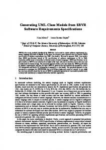
Fig. 19. Resistance of one pin of the 32-pin package. Note that the 32nd-order model corresponds to one mode per pin, which is equivalent to a single constant R and L element and thus shows no frequency dependence.
is adequate. Also, even though the original model had a dense spectrum of poles up to , PRIMA successfully chose a small number to captured the behavior. Next, the spiral is discretized to model skin effect generating a 2117 filament model. The plane is thin and does not require refinement. Figs. 10–12 show the resistance, inductance, and pole locations, respectively, for PRIMA models of order 7, 15, 30, and 45. Again, a model of order 7 captured the proximity of the plane well, but a very large order is needed to capture the skin effect. As can be seen from poles of Fig. 12, the spectrum , but as the order is of the full system now extends to increased beyond 7, most of the added poles are in the range . These added low-frequency poles are weak and do not contribute to an improved frequency response. To find a nearly optimal lower order model, TBR is applied to a sixtieth-order PRIMA model. Results for resistance and inductance are shown in Figs. 13 and 14. Figs. 15 and 16 show relative error. The pole locations of Fig. 17 shows that the many weak poles are not included in the TBR models as desired. Now only a ninth-order model was required to capture the resistance and inductance representing a factor-of-five reduction in the size of the model. To compare the computational costs of TBR, note that since the PRIMA model is only of size 60, the cost of the computing the TBR model is small compared to the 60 matrix vector products to generate the PRIMA model. If instead we wished to compute a ninth-order model with a multipoint approach, then assuming we could optimally pick the expansion points, the nine would each require roughly 27 iterative solves of iterations per solve. Since each iteration requires computation equal to that of one PRIMA step, this model would require the same computation as a 243rd-order PRIMA model. Thus the PRIMA-TBR approach is four times more computationally efficient. B. 32-Lead Quad Flat Pack
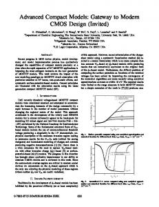
Fig. 20. Self-inductance of one pin of the 32-pin package. Note that the 32nd-order model corresponds to one mode per pin, which is equivalent to a single constant R and L element and thus shows no frequency dependence.
A coarse discretization required 856 filaments. Figs. 7–9 show the resistance, inductance, and pole locations, respectively, for PRIMA models of order 3, 5, 7, and 9. Since the PEEC equivalent circuit contains only and , the poles are all real and negative. From the figures, it is clear that a seventh-order model
As another example, consider the 32–lead package shown in Fig. 18. The model includes leads, package planes, wire bonds, and pieces of the underlying printed circuit board. The discretization of the entire model contains roughly 13 000 filaments and required an 1152nd-order PRIMA model to represent the 32 conductor self and mutual resistances and inductances. Applying TBR brought the order down to 256 for roughly 2% accuracy as shown in Figs. 19 and 20 for the self inductance and resistance of one pin of the package. The errors are shown in Figs. 21 and 22. The figures correspond to the self terms of one pin. The mutual terms have similar accuracy. The results for the spiral in the previous example are encouraging. The presence of the plane near the spiral causes a large change in the inductance as the frequency rises and was captured with a low order model. On the other hand, for the seven pins, the change in the inductance is slight yet more than eight modes per pin are required to capture the change in both the resistance and inductance. Such a result still obeys the error bound (12), since the resistance is small compared to the reactance at the higher frequencies. Note that for both models, if an accurate resistance model is not needed then a lower model is adequate to capture the inductance.
KAMON et al.: GENERATING NEARLY OPTIMALLY COMPACT MODELS
Fig. 21.
Error in resistance for one pin of the package.
Fig. 22.
Error in inductance for one pin of the package.
V. SUMMARY AND FUTURE WORK In this paper, we presented a two-step approach to generating reduced-order models of the frequency dependent inductance and resistance of 3-D interconnect. The approach involves first generating models via PRIMA and then postprocessing them via the truncated balanced realization approach. The combined strategy can lead to approximately a factor of five compaction of the reduced model when skin effect is important. The final models require less than ten modes per conductor, which would make it efficient to simulate the interaction of multiconductor interconnect with nonlinear devices. REFERENCES [1] A. Deutsch, “Electrical characteristics of interconnections for high-performance systems,” Proc. IEEE, vol. 86, no. 2, pp. 315–355, Feb. 1998.
247
[2] J. E. Schutt-Aine and R. Mittra, “Scattering parameter transient analysis of transmissions lines loaded with nonlinear terminations,” IEEE Trans. Microwave Theory Tech., vol. MTT-36, pp. 529–536, 1988. [3] A. J. Gruodis and C. S. Chang, “Coupled lossy transmission line characterization and simulation,” IBM J. Res. Develop., vol. 25, pp. 25–41, 1981. [4] L. M. Silveira, M. Kamon, and J. K. White, “Algorithms for coupled transient simulation of circuits and complicated 3-D packaging,” IEEE Trans. Comp., Hybrids, Manufact. Technol. B, vol. 18, pp. 92–98, February 1995. [5] C. P. Coelhos, J. R. Phillips, and L. M. Silveira, “Robust rational function approximation algorithm for model generation,” in Proc. 36th ACM/IEEE Design Automation Conf., New Orleans, LA, June 1999, pp. 207–212. [6] A. E. Ruehli, “Equivalent circuit models for three-dimensional multiconductor systems,” IEEE Trans. Microwave Theory Tech., vol. 22, pp. 216–221, Mar. 1974. [7] L. M. Silveira, M. Kamon, and J. K. White, “Efficient reduced-order modeling of frequency-dependent coupling inductances associated with 3-D interconnect structures,” IEEE Trans. Comp., Packag., Manufact. Technol. B, vol. 19, pp. 283–288, May 1996. [8] P. Feldmann and R. W. Freund, “Efficient linear circuit analysis by Padé approximation via the Lanczos process,” in Proc. EURO-DAC’94 with EURO-VHDL’94, Sept. 1994. [9] W. B. Gragg and A. Lindquist, “On the partial realization problem,” Linear Algebra and its Appl., vol. 50, pp. 277–319, 1983. [10] K. Gallivan, E. Grimme, and P. Van Dooren, “Asymptotic waveform evaluation via a lanczos method,” Appl. Math. Lett., vol. 7, no. 5, pp. 75–80, 1994. [11] A. Odabasioglu, M. Celik, and L. Pileggi, “Prima: Passive reduced-order interconnect macromodeling algorithm,” in Proc. Int. Conf. Computer Aided-Design, San Jose, CA, Nov. 1997. [12] L. M. Silveira, M. Kamon, I. M. Elfadel, and J. K. White, “A coordinate-transformed Arnoldi algorithm for generating guaranteed stable reduced order models of RLC circuits,” in IEEE/ACM Int. Conf. Computer Aided-Design, San Jose, CA, Nov. 1996. [13] M. Kamon, N. Marques, L. M. Silveira, and J. White, “Automatic generation of accurate circuit models of 3-D interconnect,” IEEE Trans. Comp., Packag., Manufact. Technol. B, vol. 21, pp. 225–240, Aug. 1998. [14] B. Moore, “Principal component analysis in linear systems: Controllability, observability, and model reduction,” IEEE Trans. Automat. Contr., vol. AC-26, pp. 17–32, February 1981. [15] P. Rabiei and M. Pedram, “Model-order reduction of large circuits using balanced truncation,” in Proc. Asia and South Pacific Design Automation Conf., Feb. 1999, pp. 237–240. [16] I. M. Jaimoukha and E. M. Kasenally, “Implicitly restarted Krylov subspace methods for stable partial realizations,” SIAM J. Matrix Anal. Appl., vol. 18, no. 3, pp. 633–652, 1997. [17] J.-R. Li, F. Wang, and J. White, “An efficient lyapunov equation-based approach for generating reduced-order models of interconnect,” in Proc. 36th Design Automation Conf., New Orleans, LA, June 1999, pp. 1–6. [18] M. Kamon, M. J. Tsuk, and J. White, “FastHenry: A multipole-accelerated 3-d inductance extraction program,” IEEE Trans. Microwave Theory Tech., vol. 42, pp. 1750–1758, Sept. 1994. [19] A. E. Ruehli, “Inductance calculations in a complex integrated circuit environment,” IBM J. Res. Develop., vol. 16, pp. 470–481, Sept. 1972. [20] P. A. Brennan, N. Raver, and A. Ruehli, “Three dimensional inductance computations with partial element equivalent circuits,” IBM J. Res. Develop., vol. 23, no. 6, pp. 661–668, November 1979. [21] L. M. Silveira, I. M. Elfadel, J. K. White, M. Chilukura, and K. S. Kundert, “Efficient frequency-domain modeling and circuit simulation of transmission lines,” IEEE Trans. Comp., Packag., Manufact. Technol. B, vol. 17, pp. 505–513, Nov. 1994. [22] L. Greengard and V. Rokhlin, “A fast algorithm for particle simulations,” J. Comput. Phys., vol. 73, no. 2, pp. 325–348, Dec. 1987. [23] K. Nabors and J. White, “Fast capacitance extraction of general threedimensional structures,” IEEE Trans. Microwave Theory Tech., vol. 40, June 1992. [24] E. Chiprout and M. S. Nakhla, “Analysis of interconnect networks using complex frequency hopping (CFH),” IEEE Trans. Computer-Aided Design, vol. 14, pp. 186–200, Feb. 1995. [25] K. Glover, “All optimal Hankel-norm approximations of linear multivariable systems and their L error bounds,” Int. J. Control, vol. 36, pp. 1115–1193, 1984. [26] M. G. Safonov and R. Y. Chiang, “A schur method for balanced-truncation model reduction,” IEEE Trans. Automat. Contr., vol. 34, pp. 729–733, July 1989.
248
IEEE TRANSACTIONS ON CIRCUITS AND SYSTEMS—II: ANALOG AND DIGITAL SIGNAL PROCESSING, VOL. 47, NO. 4, APRIL 2000
[27] K. J. Kerns, I. L. Wemple, and A. T. Yang, “Stable and efficient reduction of substrate model networks using congruence transforms,” in Proc. IEEE/ACM Int. Conf. Computer-Aided Design, San Jose, CA, Nov. 1995, pp. 207–214. [28] J. Park, S. Bhattacharya, and M. Allen, “Fully integrated passives modules for filter applications using low temperature processes,” in Proc. Int. Symp. Hybrid Microelectronics, Minneapolis, MN, 1997, pp. 592–597.
Mattan Kamon received the B.S degree in engineering science and the M.A. degree in mathematics in 1991 from Pennsylvania State University, University Park, PA, and the M.S. and Ph.D. degrees in electrical engineering and computer science in 1994 and 1998, respectively, from the Massachusetts Institute of Technology, Cambridge, MA. For his graduate, work he developed efficient algorithms for 3-D interconnect parameter extraction and simulation. He joined Microcosm Technologies, Cambridge, MA, after graduation, where he has developed computer-aided design tools for fast inductance and magnetic-force calculation for package analysis and microelectromechanical system design.
Frank Wang received the B.S. degree in engineering science from Peking University, Beijing, in 1994, and the Master’s degree in electrical engineering and computer science from the Massachusetts Institute of Technology, Cambridge, MA, in 1998, where he is currently working toward the Ph.D. degree. His current research interestes include modeling and numerical computation for the inductance extraction of interconnects packaging.
Jacob White (S’80–M’83) received the B.S. degree in electrical engineering and computer science from the Massachusetts Institute of Technology (MIT), Cambridge, MA, and the S.M. and Ph.D. degrees in electrical engineering and computer science from the University of California at Berkeley. He was with the IBM T. J. Watson Research Center during 1985–1987, and then held the position of Analog Devices Career Development Assistant Professor at MIT during 1987–1989. During 1988, he was a Presidential Young Investigator. He is currently a Professor at MIT. His research interests are in serial and parallel numerical algorithms for problems in circuit, interconnect, device, and microelectromechanical system design. Dr. White was an Associate Editor of the IEEE TRANSACTIONS ON COMPUTER-AIDED DESIGN from 1992 to 1996.