CO2P3S, a pattern-based parallel programming system that generates parallel ... we can find common patterns in the design that captures the experience in ...
Generating Parallel Programs from the Wavefront Design Pattern John Anvik, Steve MacDonald, Duane Szafron, Jonathan Schaeffer, Steven Bromling and Kai Tan Department of Computing Science, University of Alberta {janvik, stevem, duane, jonathan, bromling, cavalier} @ cs.ualberta.ca Abstract Object-oriented programming, design patterns, and frameworks are common techniques that have been used to reduce the complexity of sequential programming. We have applied these techniques to the more difficult domain of parallel programming. This paper describes CO2P3S, a pattern-based parallel programming system that generates parallel programs from parallel design patterns. We demonstrate CO2P3S by applying a new design pattern called the Wavefront pattern to three problems. We show that it is quick and easy to use CO2P3S to generate structurally correct parallel programs with good speed-ups on shared-memory computers.
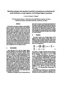
1. Introduction Parallel programming potentially offers substantial performance improvements to computationally-intensive problems. To realize this potential, programmers must develop highly concurrent algorithms that can execute on massively-parallel systems. The need for such algorithms and systems arises from complex problems in fields such as computational biology and chemistry. These problems can take hours, days, or weeks of processing time. Unfortunately, designing efficient, highly concurrent algorithms that effectively exploit multiprocessor computer systems is a daunting task that usually falls on a small number of experts. While the range of problems that can benefit from parallelism appears almost boundless, the range of solutions to these problems exhibits a degree of commonality. By extracting the communication and synchronization elements from these parallel solutions, we can find common patterns in the design that captures the experience in building parallel programs. This idea is known in sequential programming as design patterns [5]. In this paper we describe several parallel programs that use wavefront computations. Each element computes a value that depends on the computation of a set of previous elements. The computation typically flows from one region to another as shown in Figure 1, and this flow is what gives the wavefront its name. In Figure 1, each element depends on the values to its north (N), west (W) and northwest (NW). The wavefront frontier is denoted by the thick black stair-case line. At the point of the computation of Figure 1, elements above the frontier have been computed and elements below it have not. Concurrency can be obtained by using different processors to compute multiple elements at the same time,
as long as each element is computed after the elements that it depends on. For example, if 4 processors were available, 4 of the 5 shaded elements just below the frontier could be computed concurrently. 1 NW
2
W
N
3
4
4
5
3
4
5
6
4
5
6
7
Figure 1: A wavefront computation. To increase the granularity of the computation for each processor, the individual elements can be grouped into larger blocks and each block can be assigned to a processor. For example, Figure 1 shows 16 blocks, each containing 6x6 = 36 elements. However, in evaluating a block, elements on the boundary require values from adjacent blocks. This boundary exchange defines the communication and synchronization structure. The numbers in Figure 1 show the concurrency. In time step 1, only the single block labeled 1 can be computed. In time step 2, the two blocks labeled 2 can be computed, each by a different processor. In time step 3, three processors can be used. In time step 4, all 4 processors can be used. In time steps 5, 6 and 7, the number of processors used is 3, 2 and 1 respectively. To increase processor utilization, more blocks could be created. However, this will reduce the granularity of each block. Wavefront computations form a pattern that is recognized by experienced parallel programmers, with a few details that vary from application to application. In object-oriented computing, design constructs that can be re-used between applications are often expressed as design patterns [5], which capture design experience at an abstract level. By their nature, design patterns are applicable to different problem domains, each with its own individual characteristics and concerns. A design pattern is a description of a solution to a general design problem that must be adapted for each use. Once a user elects to use a design pattern, most of the basic structure of the application can be inferred. We want to take advantage of this knowledge in a more concrete manner.
To do so, we look to object-oriented frameworks from sequential programming [6]. Frameworks are a set of classes that implement the basic structure of a specific kind of application. This structural code defines the classes in the application and the flow of control through these classes. The user of a framework must subclass the framework classes to provide implementations of key components and compose these classes into an application. Frameworks are similar to libraries in some respects. However there is an important difference. When a library is used, a programmer must define the structure of the application and make calls to the library code. Conversely, a framework defines the structure of an application and the programmer supplies code for specific application-dependent routines. Frameworks allow programmer to reuse the overall design of an application, and capitalize on the use of object-oriented techniques such as encapsulation and code reuse. Frameworks can reduce the effort required to build applications [6]. We can combine frameworks and design patterns by considering the application domain of the framework to be the implementation of a pattern. For instance, consider the description of a Wavefront design pattern. Most wavefront algorithms share the same basic structure with only a few application-dependent properties. We can encapsulate this structure into a framework that implements a basic wavefront. The structural code uses classes that define the application-dependent properties of a wavefront without implementing them, such as the function that computes the value of an element from the value of its predecessors. A user of this wavefront framework supplies these properties by either providing subclasses that contain the needed implementation or by composing framework-supplied classes that modify the basic structure to better fit the application. CO2P3S generates correct framework code from a design pattern description of the application structure. In contrast, other systems provide the ability to specify the structure with patterns but rely on the user to write application code that matches the parallel specification. High-level parallel programming tools have failed to become mainstream for a number of reasons, including lack of generality and mediocre application performance. The concept of design pattern templates introduced in CO2P3S is a major step in addressing these concerns. Section 2 describes design pattern templates and frameworks. Section 3 describes the Wavefront design pattern template and its parameters. Section 4 gives three example problems that illustrate how this single new CO2P3S design pattern (the Wavefront) can be used to generate several parallel programs that run on a sharedmemory computer. These programs show how CO2P3S can quickly create parallel programs that are structurally correct and provide good parallel performance with little coding effort. Section 5 presents an implementation of the
Wavefront design pattern template. Finally Section 6 provides our conclusions and discusses future work.
2. Pattern Templates and Frameworks A design pattern has several variations on its structure and implementation to accommodate many applications. Therefore, a design pattern is really a family of solutions to a family of problems. For example, the Wavefront pattern has several variations. Recall that each element in a wavefront computation relies on values from neighboring elements. The designation of dependent neighboring elements is one variation of the Wavefront pattern. Figure 1 illustrated one dependency set {W, N and NW}. In Section 4 we describe a biological sequence alignment algorithm that has this dependency set, and two other applications with different dependency sets. To exploit patterns as families of solutions, we introduce an intermediate form called a design pattern template. A template represents the basic structure of the pattern with parameters to specialize the template for common alternatives. Patttern templates are a parametrically related family of solutions, much like the patterns they are based upon. Using these templates, a user can select the member of the family that best represents the structure required for an application. For example, the neighbor dependency set is one parameter for the Wavefront design pattern template. The usefulness of a pattern template must be balanced against its generality. More parameters provide a large number of alternative structures, at the expense of specification complexity. Conversely, fewer parameters may mean that some aspects of the basic structure cannot be modified using the template. This could limit the range of applications to which the template may be applied. Striking this balance requires consideration of the alternatives on a pattern-by-pattern basis. A pattern-based method can be used to build parallel programs from a palette of different design pattern templates. The first step is to select the pattern template(s) that represents the best parallel structure for an application. This step is not addressed by our research. It is possible for users to select a pattern template that is inappropriate for a particular problem. However, there are several methodologies for finding the best parallel structure for an application [3,4]. In addition, there are parallel design pattern languages (such as [9]), which describe a set of patterns that guide users to the most appropriate parallel structure for a problem. The user selects one or more pattern templates and then supplies the required parameters. Each pattern template requires some class names for the generated framework class. In addition, there are other templatespecific parameters, such as the neighbor dependency set for the Wavefront pattern.
2
Once the pattern(s) and its parameter(s) have been specified, the system (CO2P3S in our case) generates the code that implements the specific pattern structure. This framework consists of abstract classes that implement the parallel structure of the pattern (concurrency, communication, and synchronization), a set of concrete classes for inserting user application code, and any required collaborator classes. The structural code defines the flow of control in the framework based on a set of collaborating abstract classes. A user supplies subclasses that override hook methods to implement a specific application. These subclasses are invoked from the structural code through the use of well-known sequential patterns like the Strategy or the Template Method [5]. The complete application is created when the user combines the framework-generated classes with application-specific subclasses. Two crucial aspects of CO2P3S are that the generated frameworks correctly implement the pattern structure and that structural parts are hidden from the user. The user can only supply sequential hook method implementations to the framework at this layer. The user starts with the correct structure and cannot introduce errors into it. This allows the user to concentrate on the application rather than on the parallel framework code that executes it. This is an improvement over current parallel programming systems, which still require that the user consider parallel structure issues during program development. The implementation details of the framework are hidden from the programmer. To change the parallel structure of a program, the user changes a parameter for the pattern template and regenerates the framework code. Although this new framework may introduce additional hook methods that need to be implemented, hooks that were previously implemented are included in the regenerated framework automatically. Alternately, to obtain larger structural changes, the programmer may select a completely different design pattern. In this case, the programmer will need to implement different hook methods; application code will need to be moved from the old hook methods to the new ones. For example, the framework for the Wavefront pattern template uses a Strategy pattern to handle different dependency sets. In a normal framework, the user creating an instance of a wavefront would need to create the correct strategy object and supply it to the wavefront framework. Our approach allows the user to specify the parameters in the template, and the generated framework internally composes the wavefront classes with the correct strategy. The user does not even know how the dependency sets are handled in the framework, but simply treats the generated framework as a wavefront with the desired dependency sets. Further, a user interface ensures that dependency sets are always specified, so that a correct structure is always created.
The structural code in the framework correctly handles the difficult aspects of the parallel structure, such as communication, synchronization, and creating the concurrency. In contrast, if users had to write this code by hand, the program writing effort would increase substantially. The structural code is not only a significant amount of the code for a complete application, it is also the code that is the most error prone, and the most difficult to debug. Generating this complex code saves users the time of writing and, more importantly, debugging the structure of the pattern template. Instead, users can concentrate on their applications. An important feature of the generated frameworks is that the concrete classes that are created include default implementations for all of the hook methods. Together with the generated mainline method, the frameworks can be compiled and executed immediately after they are generated. In the Wavefront framework, the computation is a trivial one that propagates correctly over all of the elements. This allows a programmer to start with a working parallel program and incrementally modify it. Overall, the most important aspect of the frameworks is that they are structurally correct. Further, the frameworks implement all of the communication and synchronization, so the user does not need to include any parallel code in the hook methods for their application. This approach to correctness is unique, represents an improvement over existing parallel programming systems, and can only improve their usability.
3. Wavefront Design Pattern Template Our design-pattern-based approach to parallel programming is independent of programming language and parallel architecture. However, we have implemented a system using multithreaded Java code targeted at shared-memory multiprocessor machines and a distributed memory version is under development. The CO2P3S parallel programming system is the realization of our goal to build a system based on parallel design pattern specifications and object-oriented frameworks [7,8]. It currently supports several design pattern templates. In this paper we introduce a new design pattern template called a Wavefront, that supports the computation of elements that depend on a set of elements that must be computed first. The template parameters can be divided into two categories, design parameters and performance parameters. A design parameter affects the parallel structure of the generated framework. A performance parameter only affects the performance of the code. One kind of performance parameter is a debugging parameter. A debugging parameter is turned off after the application is debugged to improve performance. The Wavefront pattern template has three design parameters:
3
1. The name for the the Wavefront element class. 2. The shape of the element matrix. The default choice is a Full Matrix shape in which all elements of a rectangular matrix are computed. The second choice is Triangular, which supports computations over half of a matrix. The third choice is Banded which represents computations along a band of elements centered around the diagonal. Each of these different matrix shape choices will be illustrated by a separate problem in Section 4. 3. The dependency set for an element. Figure 1 illustrated the dependency set {N, W, NW}. Not all groups of directions form legal dependency sets. For example any set that contains opposite directions is illegal since they generate cyclic dependencies that result in deadlock. The user interface prevents a programmer from selecting illegal dependency sets. The Wavefront template has three performance parameters: 1. The notification method used to inform elements that a dependency constraint has been satisfied. One choice is Push, where elements signal their dependents upon completion. The other choice is Pull, where dependents poll their prerequisites for completion status. 2. The type of wavefront elements. If the type is primitive, then the user selects the specific primitive type and static methods are generated in the element class with the appropriate argument types and return types. If the element type is an object then instance methods are generated to operate on instances of the element class. 3. Whether the application needs access to nonneighboring elements. For example, in Figure 1, an element is directly dependent on three neighbors. If the element can actually be computed from the values of these three neighbors, the neighbors-only parameter would have the value true. However, if the element required all elements to the west of it, as well as the north and northwest neighbors, the neighbors-only parameter would be false. Notice that the dependency set would still be {N, W, NW} since once these values are available, the element can be computed. Figure 2 is a screenshot of the CO2P3S Wavefront template that illustrates these six parameters. The element class is called SAElement, the shape is full matrix and the graphic shows the matrix with a wavefront. The dependency set is {N, W, NW} since these directions are shaded medium (green in the interface). The invalid opposite directions are shaded dark (red in the interface). The NE and SW directions are shaded light (grey in the interface) since they are unselected but not invalid. If one of them was selected, the other would become invalid. The three performance parameters are: push, element type int, and neighbors-only equals true. The Wavefront pattern template is highly customizable and all parameters except for the class name have a large impact on the framework code generated.
The selection of element type determines whether static or instance methods are generated. The shape of the matrix has an impact on the blocking strategy and the iteration code. The dependency set determines the number of different methods required to compute the elements and the signatures of these methods. The neighbors-only parameter indicates whether neighbor elements or the whole matrix are used as method parameters.
Figure 2: The CO2P3S Wavefront pattern template. The only class the user implements is the wavefront element class. This class has three responsibilities: providing an initialization method that is called for each wavefront element, implementing the wavefront operations on a wavefront element, and supplying a method to be used for reducing the matrix after the computation is complete. The user is supplied with stubs for the appropriate hook methods depending on the parameters specified at framework creation time. For example, there are three groups of generated hook methods for the parameter choices of Figure 2, a single initialization method, a single reduction method to gather the results and four static methods that compute elements: int operateCorner(int row, int col); int operateLeft(int north, int row, int col); int operateTop(int west, int row, int col); int operateInterior(int north, int northwest, int west, int row, int col);
The framework invokes the appropriate method based on the location of the element. Each method has appropriate dependent elements as arguments and returns the computed element. Each method also has the row and column indexes as arguments in case the computation depends on these values as well. To use the Wavefront framework, the user creates a Wavefront object and uses it to launch the computation. The Wavefront object is instantiated by supplying the height and width of the matrix, the number of threads to
4
be used, an initializer object (or null if no object is needed), and a reducer object (or null if no object is required). Optionally, the Wavefront object can be created with a blocking factor that specifies the minimum number of blocks of wavefront elements to create along each axis of the matrix. If no blocking factor is supplied, a default factor is used. The value for this default (100 blocks by 100 blocks) has been determined empirically, and is acceptable across a number of applications. The framework is responsible for partitioning the matrix into blocks, creating threads, and executing the computations. The user simply has to launch the computation, which returns when all of the wavefront elements have been computed and the matrix has been reduced.
and some application-specific data structures. In this case the row and column indices are used to access these data structures. Specifically, the value for an element in a given row, r, and column, c, is: Formula 1: DPM[r, c] = max (W - gapPenalty, N - gapPenalty, NW + score(r, c)).
In the simplest case, the gap penalty is a fixed constant. The score is a function that maps two letters that represent amino acids to an integer representing their similarity. For example, if we are computing the value of the element in the fourth row (V) and third column(L) of Figure 2, we would use score(4, 3). The score function can be represented by a similarity matrix with constant entries, like score(4, 3) = similarity[V, L] = 12. If we use a gap penalty of 10, then Formula 1 yields:
4. Using the Wavefront Pattern In this section, we describe the development of three applications that use different parameter values of the Wavefront. We concentrate on the pattern specification and the application code written by the user, and show that we are able to obtain reasonable performance gains without having to modify the generated code.
Formula2: DPM[4, 3] = max (W - 10, N - 10, NW + score(4,3)) = max (DPM[4, 2] - 10, DPM[3, 3] - 10, DPM(3, 2) + 12) = max(0-10, 20-10, 10+12) = 22.
In this example, the initialization method does nothing. The reducing method simply collects the optimal alignment score, the element at the bottom left corner. The performance of the sequence alignment application is given in Table 1. These speedups are not necessarily the best that can be achieved, as the blocking factor greatly affects the results. They are meant to show that for a little effort, it is possible to quickly build a parallel program with reasonable speedups. Once we decided to use the Wavefront pattern template, the correct parallel structure for the specific wavefront that solves this problem was generated in a matter of minutes. Using the available sequential code, the remainder of the application was implemented in about an hour.
4.1 Biological Sequence Alignment Using Dynamic Programming Consider a dynamic programming matrix (DPM) that is generated by a biological sequence alignment algorithm, as shown in Figure 3 [10]. The computation proceeds from the top left corner to the bottom right corner. Except for the top row and left column, each element in the DPM depends on the values of three elements in the directions, N, W and NW, as well as some application specific data structures. The Wavefront parameters for this application are shown in Figure 2.
T D V L K A D
0 -10 -20 -30 -40 -50 -60 -70
T -10 20 10 0 -10 -20 -30 -40
L -20 10 20 22 20 10 0 -10
D -30 0 30 20 22 20 10 20
K -40 -10 20 30 20 42 32 22
L -50 -20 10 32 50 40 42 32
L -60 -30 0 22 52 50 40 42
K -70 -40 -10 12 42 72 62 52
Processors sequential 2 3 4
D -80 -50 -20 2 32 62 72 82
Time (sec) 40.5 22.6 15.3 11.6
Speedup 1.79 2.65 3.48
Table 1: Wall clock times and speedups for the sequence alignment example. The program was run using two 10,000 character sequences and the default blocking strategy was used (100 blocks by 100 blocks). It ran using a native threaded Java implementation from SGI (Java 1.3) with optimizations and JIT turned on. The execution environment was an SGI Origin with 4 processors and 1GB of RAM. The virtual machine was started with 512MB of heap space. The speedups are based on the average wall clock time for ten executions compared to a sequential program executing on a native threaded virtual machine. The speedups only include computation time and exclude initialization, reduction, and output. From Table 1, we can see that the problem scales well up to four processors.
Figure 3. A dynamic programming matrix for biological sequence alignment. In this application, the four operate hook methods were implemented as follows. The operateCorner() method returns 0. Note that the row and column indexes are not used in this case. The operateLeft() and operateTop() methods return the fixed values on the left and top edge respectively. The operateInterior() method computes the element value based on the three adjacent elements, N, W and NW
5
Four operate methods corresponding to the ones described in Section 3 are also generated. However, since elements in this application depend directly on nonneighboring elements, the operate methods require access to non-neighboring elements. This means that the entire matrix is used as a parameter to each of the operate methods. This also means that the particular neighbors, W and N are omitted as parameters since they can be accessed from the matrix. These parameters are replaced with an instance of the Matrix class that can be used to access the data in the matrix. For example, the operateInterior() method becomes:
4.2 The Skyline Matrix Problem The Cowichan problem set [13] is used for evaluating the expressive power and performance of parallel programming systems. It contains two problems that can be solved using the Wavefront pattern. One of these problems is the LU-Decomposition of a skyline matrix. A skyline matrix is a square matrix where each subdiagonal row and supra-diagonal column has a (possibly zero-length) prefix of zero-valued elements. While any matrix can be viewed as satisfying the skyline property, those matrices that have a substantial zero-element portion hold the most interest. Sparse matrices with elements clustered near the diagonal are good examples of skyline matrices. An example of a skyline matrix is given in the left side of Figure 4. Doolittle's Method is used to perform the LUDecomposition of a skyline matrix [1]. The value of an element aij is computed using Formula 3 or Formula 4.
int operateInterior(Matrix m, int row, int col);
As before, the row and column are the indices of the element to be computed. Inside of this method, the programmer needs to access the matrix elements. Since the programmer does not know the internal structure of the Matrix class, an accessing method is provided:
Formula3: Lij = aij - sum(lik * ukj) / ujj
(lower triangular).
int getElement(int row, int col);
Formula4: Uij = aij - sum(lik * ukj)
(upper triangular).
It is dangerous to set the neighbors-only parameter to false since the programmer has access to all of the matrix elements, even those that may not have been computed yet. The programmer is trusted to access only the computed values. The solution to this problem is to throw an exception when the program tries to access an uncomputed value. However, since this check is expensive, it should be turned off after the user is done testing and ready to generate production code. This is an example of a debugging performance parameter, but we have not implemented it yet. The program was run on a 50% full 1,000 x 1,000 matrix of random values using the same hardware/software configuration as the sequence alignment problem. The performance results are shown in Table 2. The times are the average of ten executions. The default blocking strategy produced near linear speedups.
These formulas generate the following dependency relationships that are shown in the right side of Figure 4: • Elements in the lower triangle are dependent on all elements to its left in the same row and all elements from the upper triangle in the same column. • Elements in the upper triangle are dependent on all elements above it in the same column and all elements of the lower triangle in the same row.
Processors sequential 2 3 4
Figure 4: A skyline matrix and its dependency relationships. As Figure 4 shows, the dependency set of an individual matrix element is {W, N}, the matrix shape is banded, and the neighbors-only flag is false. The banded matrix shape generates two static hook methods to compute the size of the bands.
Time (sec) 64.1 35.3 21.7 16.4
Speedup 1.81 2.96 3.92
Table 2: Wall clock times and speedups for the skyline matrix example.
4.3 The Matrix Product Chain Problem
int startRow(int column);
Our final example of the Wavefront pattern is another problem from the Cowichan problem set. The Matrix Product Chain (MPC) problem can be solved using a dynamic programming matrix (DPM) [13]. The goal is to find the best order for multiplying a series of matrices to minimize the number of computations. For example, for matrices A, B, C, and D having sizes 6 x 3, 3 x 5, 5 x 12,
int startColumn(int row);
The framework uses these methods to compute the size of the band. The startRow() method is called by the framework, once for each column and the startColumn() method is called once for each row.
6
and 12 x 2 respectively, the cost of doing the multiplications ranges from 186 for A(B(CD)) to 594 for ((AB)C)D). The minimum cost for the multiplications can be found by using the upper triangular portion of a DPM where the values represent the least cost ordering of multiplications for multiplying matrices Mi to Mj. The value of an element is calculated by finding the least cost of multiplying Mi to Mk and Mk+1 to Mj for i < k < j and then using those values to find the cost of multiplying the resulting matrices. Since the values of the matrix may be found in a diagonal-by-diagonal way, this problem is suited to the Wavefront pattern. Unlike the previous two examples, in which elements were calculated from the top left-hand corner to the bottom right-hand corner, the MPC problem calculates from the diagonal of the matrix to the top right-hand corner. This changes the pattern template parameters. The matrix shape is triangular as opposed to full-matrix or banded. The dependency set is now {S, W} instead of {W, N, NW} or {N, W}. Due to the triangular shape of the matrix and the inclusion of S in the dependency set, the corner elements are now found along the diagonal and the remaining elements are interior elements. Therefore, only two operation methods are generated: o p e r a t e C o r n e r ( ) and operateInterior(). Finally, this problem has non-neighbor dependencies so the operate methods have a Matrix parameter as described in the skyline matrix problem. Although these are all of the changes that the programmer might notice, there is another internal change in the framework. In the previous two examples, the initial working set contained a single element (the top left-hand corner). However, the initial working set for a triangular shaped matrix with dependency set {S, W} contains all elements along the diagonal. It is one of the major advantages of our approach that the user does not have to be aware of such structural changes. In this example, the initialization method sets all the costs along the diagonal to 0 and all other costs to a maximum value. The reduction method stores the top right-hand value in the reducer object. The operateInterior() method uses an applicationspecific array, dimension[], created and initialized by the programmer:
problems. Matrices of random dimensions between 10 and 100 were used and the matrix was divided into 10 x 10 blocks. This is an example where the default blocking factor is inappropriate for the problem. Since the top right corner must access elements on the entire length and width of the matrix, it represents the largest piece of work. Since it is also the final piece of work, only a single thread will be performing the calculations for that block. Therefore we would like to minimize the block size to increase the amount of parallelism without creating unnecessary overhead. The performance results are shown in Table 3. Again the speedups are based on the average wall clock time for ten executions. Note that despite the disproportional amount of computation in the last few blocks, the application has near-linear speedup. This is due to experimentally fine-tuning the application by finding a good block size for this application. Processors sequential 2 3 4
Time (sec) 87.9 44.2 29.7 22.4
Speedup 1.99 2.96 3.93
Table 3: Wall clock times and speedups for the matrix product chain example.
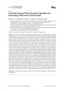
5. The Wavefront Implementation The delegation of work to threads in the Wavefront pattern is handled by a work queue. Access to the work queue is via a controller object. The controller handles requests to add and remove work from the queue, as well as tracking the amount of work completed so that it can stop the threads when the computation has finished. We define two kinds of synchronization for the workflow. In diagonal synchronization, an element is added to the work queue when all elements of the previous diagonal have completed their computation. In prerequisite synchronization, an element is added to the work queue as soon as its prerequisite constraints have been satisfied. In Figure 1 the numbers represent time steps in either diagonal or prerequisite synchronization when 4 processors are used. However, in general, diagonal synchronization is slower than prerequisite synchronization. For example, Figure 5 shows the same wavefront matrix as Figure 1, but with more blocks. The left matrix is labeled by time steps for diagonal synchronization and the right matrix is labeled by time steps for prerequisite synchronization. In both cases, 4 processors are used. CO2P3S uses prerequisite synchronization for the Wavefront. However, it easy to compute the theoretical maximum speedup in the case of diagonal synchronization as a function of the number of blocks and processors. This theoretical maximum can be used to experimentally determine the amount of overhead for the
minCost = Integer.MAX_VALUE; for(k = row to column-1) do cost = aMatrix.getElement(row,k) + aMatrix.getElement(k+1,column) + dimension[k+1] + dimension[column+1]; if (cost < minCost) minCost = cost; end do; return minCost;
The program was run using the same hardware/software configuration as the previous two
7
Wavefront pattern (not counting synchronization waits). Table 4 shows speedups for a version of the sequence alignment example that uses diagonal synchronization and shows how close they come to the theoretical limit. The difference between these two values gives an indication of the relative overhead for the Wavefront framework. This is a fairly small overhead considering how rapidly a wavefront application can be created. Note that the speedups with prerequisite synchronization given in Table 1 are better (as they should be).
1 2
2 3 3 4
4 5
5 7
7 9
1 2 2 3
3 4
4 5
5 6
6 7
3
4 5
7
9 11
3 4
5
6
8
9
4 6
5 7 9 11 12 8 9 11 12 13
4 5 6 7
7 8
8 9 10 9 10 11
8 10 11 12 13 14
7 8
9 10 11 12
not include the Wavefront template described in this paper. It was added recently using Meta-CO2P3S. Current research also includes finding new patterns to add to CO2P3S and improving the support for distributed patterns. Future research will address tool support. Currently, CO2P3S supports program development, compilation, execution and pattern addition. Debugging and performance tools will be needed to produce a fully featured, mature parallel programming environment.
Acknowledgements This research was supported by grants from the Natural Science and Engineering Research Council of Canada and PENCE.
References 1.
2.
Figure 5: Diagonal and prerequisite synchronization with 4 processors.
3. Processors 2 3 4
Actual speedup 1.66 2.41 3.04
Theoretical speedup 1.99 2.94 3.88
Relative overhead 17% 18% 22%
4. 5.
Table 4: Theoretical versus actual speedup.
6.
6. Conclusions and Future Research
7.
In this paper, we described a new approach to writing parallel programs that is based on generating structural framework code from a pattern description of the problem. We demonstrated that this approach can be used to build correct, working parallel programs that yield performance benefits. We have also shown that our design pattern templates provide a family of framework solutions that can be applied to different problems. Three of the example problems discussed in the paper, sequence alignment, skyline matrices and matrix product chain, are all implemented with the same Wavefront pattern template. Additional applications using different patterns can be found in [8]. The frameworks generated by CO2P3S were originally targeted at shared memory multiprocessors. We are currently creating distributed memory versions of the pattern templates, taking advantage of the facilities available in JINITM [11] and JavaSpacesTM [12]. We have also customized RMI to use a more compact serialization scheme to improve performance. A recurring problem in programming systems based on design patterns is that they are limited by the set of patterns they support. We are currently working on a tool called Meta-CO2P3S [2] that can be used to add new patterns to CO2P3S. The original version of CO2P3S did
8.
9.
10.
11.
12.
13.
8
D. Bouman. Parallelizing a Skyline Matrix Solver using Orca, Student report, http:// www.cs.vu.nl/~bal/cowican.html, 1995. S. Bromling. Meta-programming with Parallel Design Patterns, Master's thesis, Department of Computing Science, University of Alberta, 2002. K. Mani Chandy and S. Taylor. An Introduction to Parallel Programming. Jones and Bartlett Publishers, 1992. I. Foster. Designing and Building Parallel Programs. Addison-Wesley, 1995. E. Gamma, R. Helm, R. Johnson, and J. Vlissides. Design Patterns: Elements of Reusable Object-Oriented Software. Addison-Wesley, Reading, Massachusetts, 1994. R. Johnson. Frameworks = (components + patterns). Communications of the ACM, 40(10):39-42, October 1997. S. MacDonald, D. Szafron, and J. Schaeffer. Objectoriented pattern-based parallel programming with automatically generated frameworks. In Proceedings of the 5th USENIX Conference on Object-Oriented Technology and Systems (COOTS'99), pages 29-43, 1999. S. MacDonald. From Patterns to Frameworks to Parallel Programs. PhD thesis, Department of Computing Science, University of Alberta, 2001. B. Massingill, T. Mattson, and B. Sanders. Patterns for parallel application programs. In Proceedings of the Sixth Pattern Languages of Programs Workshop (PLoP'99), 1999. Proceedings available at http://stwww.cs.uiuc.edu/~plop/plop99/proceedings/. S. Needleman and C. Wunsch, A general method applicable to the search for similarities in the amino acid sequences of two proteins. Journal of Molecular Biology, 48, 443-445, 1970. Sun Microsystems. JINITM Technology Architectural Overview. Available at http:// www.sun.com /jini/whitepapers/architecture.html, 1999. Sun Microsystems. JavaSpacesTM Service Specification. Available at http:// www.sun.com/jini/specs/jini1.1html/jstitle.html, 2000. G. Wilson. Using the Cowichan problems to assess the usability of Orca. Proceedings of IFIP Working Conference on Programming Environments for Massively Parallel Distributed Systemsy, 183-193, 1994.