Grid-Code-Based Fast Matching Method in Active Binocular Vision Chen Mingzhou, Wang Zhong, Kou Xinyu, Ye Shenghua State Key Laboratory of Precision Measuring Technology and Instruments; Tianjin Univ.! Tianjin ABSTRACT Binocular machine vision has been explored for so many years, but the most difficult problem and the obstacle of the system processing is the matching procedure. This thesis will give a new technique to obtain matching points of the left and right image in the binocular active vision system, without searching the whole image, or even the whole feature curve. So the time-consumed computation is reduced considerably. And the mismatching errors are reduced too. In this technique, except the epipolar constraints, we add two strong constraints into the system: Adherent-Mark, Grid (row and column). Using a new method of Grid-Coding, matching point is easy to be found. Keywords: Epipolar Constraint, Adherent-Mark, Binocular, Arbitral Lines, Grid-Coding
1. INTRODUCTION Binocular machine vision is an important branch of machine vision. Simulating the human vision, two cameras grab the two images of the same scene from two different positions. If the parameters and the poses of cameras are calibrated beforehand precisely, 3-D coordinates of the feature points are easily obtained from the parallax. In this procedure, how
to match the feature points of the left and the right image is an important and difficult task. Stereo matching is an important technology in the 3-D scene analysis or 3-D surface measurement. Its aim is to find the corresponding target point if the source image point has been given. Many matching algorithms have been explored these yeas: Gradientbased matching algorithm is based on the information ofthe gradient distribution. Through computing gradient statistics of the 2-D image, it can obtain the comparability or relativity of the sub-windows in the left and right image '. This method has the problem of huge computation and mismatching errors. Image template matching algorithm has been
used for many years. Also, it has the problem of rotation and scale variance, requiring much image computation. Characteristic-based matching algorithm needs to obtain the characters points, and then decides matching point in a candidates queue. Using this method, we need not to search in the whole image. So the computation is reduced considerably. But the candidates are required to have definite characteristics in order to obtain high quality signals. So another matching algorithm is developed under this condition. That is epipolar constraint matching algorithm 2,3 This matching method makes use of geometric constraints formed by the image planes, optic center and the object, so its searching area is reduced to one dimension.
Grid-coding technique has been used in machine vision for many years. Y. F. Wang used it in his monocular vision system to compute the surface orientation and structure of the object His method can obtain the direction of the projected strips to infer local surface orientation only. A. Blake used a grid projector and near-degenerate epipolar alignment to obtain the depth ofthe 3-D scene 6 Gongzhu Hu used a projected grid of light to measure the 3-D surface with a single image . His method needed to obtain two transformation matrices. Tsorng-Lin Chia and Zen Chen has used grid to obtain the axis and orientation of 3-D cylinder and right circular cone 8,9
In this thesis, a new matching method is proposed. Epipolar constraint is also used as an important constraint. And two other constraints are also introduced into our binocular vision system. A new grid-coding technique is used, which makes matching procedure more easy and computation less. The details will be discussed in section III. Section II will give the binocular vision system model. Conclusions will be given at the last section.
2. MODEL OF ACTIVE BINOCULAR VISION SYSTEM The vision system is arranged as showed in the fig2-l. The patterns marked on the grid plane are projected to the freeform surface, which is to be measured, to form curves on the surface. The patterns are parallel strips marked on the film. Chen Mingzhou, Email:
[email protected]; Telephone: 86-22-2740-6643; other author information: Kou Xinyu, Email:
[email protected]; Wang Zhong, Email:
[email protected]; Ye Shenghua, Telephone: 86-22-2740-4778.
Image Matching and Analysis, Bir Bhanu, Bir Bhanu, Jun Shen, Jun Shen, Tianxu Zhang, Tianxu Zhang, Editors, Proceedings of SPIE Vol. 4552 (2001) © 2001 SPIE. · 0277-786X/01/$15.00
Downloaded from SPIE Digital Library on 14 Oct 2010 to 140.203.12.240. Terms of Use: http://spiedl.org/terms
253
Two CCD cameras are arranged at symmetrical position about projector optical axis. The camera model will be discussed as followed.
Free-Form Si
XIb
projector optical axis right image plane
Ob
x Light Source Fig2-l Active Binocular Vision System Principle
2.1 PERSPECTIVE PROJECTION MODELS OF THE CCD CAMERA In Fig2- 1, because of symmetry arrangement, we discuss left camera in detail only. The right one is the same. Define
the lens center (optical center) as the origin °a of camera coordinate system (see left part in the Fig2-1). So the camera coordinate system is constructed now. Then the intersection of Za axis and the left image plane is defined as
°Ia the origin of the image plane coordinate system. Xja axis and Yja axis are parallel to the Xa axis and Ya axis respectively. So equation can be derived through perspective projection as followed: fa
0
P L =0
fa
XL 1
0
0 0
Xa
°Ya 1
(1)
Za
Where, fa is the focal length of left CCD lens defined as Fig2-l. [XL L ]T is the coordinate of the image point P
on the left image plane. [Xa Ya Za ]T is the coordinate of the surface point p in the coordinate system of left CCD camera. The same with right CCD camera, similar equation is obtained:
XR
fb
pYR =0 1
254
0
0 0 fb 0 0
1
Xb .
Yb Zb
Proc. SPIE Vol. 4552
Downloaded from SPIE Digital Library on 14 Oct 2010 to 140.203.12.240. Terms of Use: http://spiedl.org/terms
(2)
Where, fb S the focal length ofright CCD lens defined as Fig2-1. 2.2 OBTAINING 3-D COORDINATES OF SURFACE POINT Now, the relationships between image point coordinates and surface point coordinates in CCD measuring coordinate T T system ( OaXaYa ) are obtained. Then, the relationships of [Xa Ya Za ] and [xb Yb Zb I can be defmed as equation (3) based on the geometric arrangement of left and right CCD cameras.
1 r2 i T
Xa
Xb
Xb
Ya 5 r6 T. =R Tj• Za
r7
r1
F
1
r r9 T
Yb
(3)
1
r r3
Where, R = r4 r5 r6 , r7
Yb
T rotate
matrix, and, T = T ,
transform matrix. They express the rotation and
r
translation between the coordinate system of left camera ( OaXaYaZa ) and right camera ( ObXbYbZ,, ). Every
coefficient in these two matrices must be determined beforehand precisely [10, 1 1].
From equations (1) (2) (3), 3-D coordinates ofthe point on the surface can be deduced:
z= b
fafbLfb7z XLXR faXRni +XLYR faYRr2 +XLfb4 fafb
x XbZb ib Yb =
ib
(4)
Zb
3. IMAGE MATCHING PROCEDURE From the description in the section two, if the corresponding image point coordinates of left and right are known, 3-D coordinates can be derived through equation (4). So the most important thing is to find the corresponding image point from one image when its source point is given in the other image. If we search in the whole image, computation will be egregiously large. So epipolar constraint is introduced into the vision system. At the same time, grids are used. And a new grid-coding technique is also introduced.
3.1 EPIPOLAR CONSTRAINT From the geometry of the system, it is easily to find out the epipolar constraint (shown in the Fig3-l). Camera optical
centers °a and °b set up the epipolar plane with surface point p (x, Y z). The intersection ECL of left image plane and base line (Oa Ob) is defined as left epipolar center in the left image plane. Similarly, ECR is defined as right epipolar center. It is obviously true that the image point must locate on the epipolar line, which passes through the
Proc. SPIE Vol. 4552
Downloaded from SPIE Digital Library on 14 Oct 2010 to 140.203.12.240. Terms of Use: http://spiedl.org/terms
255
epipolar center (see in Fig3-1). The coordinates of ECL and ECR can be derived from (5) if matrices R and T are known:
ECL( fa' fa)'
(5)
ECR( fb 'fb)
If the slope ka of the left epipolar line has been worked out from the left image point P and point ECL, the
slope kb can be determined by:
k — T(r4 +r5 ka) —Tfr7 +r8
bT( +r2 'ka)Ty(1 +
(6)
k)
So the matching point in the right image must be on the line, which has the slope kb and passes
T
T
z
z
through the point ECR ( fb
fb)
Matching procedure is simplified. It needs to search the epipolar line only. But it is not easy enough. It can be even simplified if grid-coding technique is used.
Fig3-1 Geometry Configuration of epipolar constraint
3.2 GRID-CODING TECHNIQUE It is true that the right image point must be located on the same edge if the corresponding left image point is located on that edge. So grids are introduced into our system. First, we grab a scene of the object without the grid projection. Then we grab the scenes with grids. So it is easy to
obtain the grid-edge images without the edges of original object (shown in Fig3-2). Grid columns are used as characteristic points to be matched. Grid rows are used as arbitral lines, which is to reduce the searching area further.
We need only find the matching points of the edges, that is, grid columns. But the problem is how
to identify the left and right grid
line
column, which is the same edge on the surface. Adherent-mark is used in our
system as it is shown in the Fig3-2. The grid-coding steps are described as followed:
grid rows
01 2 Fig3-2
grid images of left and right cameras
1. Obtain the coordinates of the adherent-mark
256
Proc. SPIE Vol. 4552
Downloaded from SPIE Digital Library on 14 Oct 2010 to 140.203.12.240. Terms of Use: http://spiedl.org/terms
It is very easy because we needn't extract the very precise coordinates of the mark. If it does locate on the same grid column and row of the left and right image, it is precise enough. If the surface is forbidden to be adhered anything, we can select a mark in the left image and also select one in the other image, based on the rule that these two marks must be located in the same area, which can be judged from the original surface image. In our experiments, we used the method of selecting the two adherent-marks in the binocular images.
2. Edge detection Find all grid columns. Because the columns will be used in matching procedure as feature points, Edge-tracing and Spline-fit technique are used to obtain the sub-pixel edge location precision. Grid rows are just used as arbitral lines, so they are extracted the edges at one-pixel edge location precision. These edges are saved as arrays that will be used in the matching procedure. 3.
Grid coding
From the adherent-mark, the grid columns and row can be coded as shown in the Fig3-4 or in the Fig3-2. All the coordinates of the grid columns are dived by grid rows and saved as edge arrays. For every column and row, it must be true that one corresponding code is attached. It is also true that the two edges must be the same edge of the grids in the binocular images if their codes are same. This is because the relationship of the edges and the adherent-mark is decided in both images. Using this rule, we can apply with several adherent-marks in one image to resolve the problem of line breaking. For space of the paper, we can't discuss it in detail. Another paper will do it.
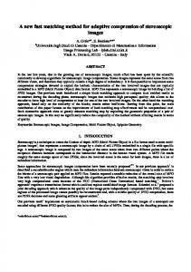
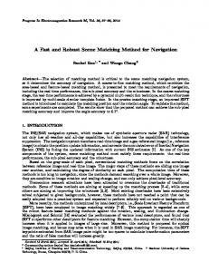
3.3 STEREO MATCHING We grab the surface images first, which is useful to reduce the influence of the original surface. Then grids images with colunm or rows only (see Fig3-3) will be captured. Edges are extracted and coded using the techniques discussed above (see Fig3-4). It is easily deduced that the grid column whose code is —1V, as shown in Fig3-4, in the left image must have the corresponding grid column whose code is also —1V in the right image. And the edge point on the one column between two grid rows in the left image must be located on the same column and between the same rows in the right image. This is true for all columns and rows.
a
b c Fig 3-3 Original images of the fan surface a is a fan without grids, b is the same fan with columns only, and c is the same fan with rows only
So once a point on one column edge segment between two rows is decided, its matching point in the other image can be found on the column edge segment between the rows with the same codes, then 3-D coordinates of the surface point can be worked out based on equation (4).
4. CONCLUSEION In this thesis, a new approach of matching the edge points of binocular images is discussed detailed. It can truly reduce the computation, which is because introducing two strong constraints into the system. It makes the matching procedure more evidently. If the density of the grid lines is increased, we can even directly look the intersections of the grid as the
Proc. SPIE Vol. 4552
Downloaded from SPIE Digital Library on 14 Oct 2010 to 140.203.12.240. Terms of Use: http://spiedl.org/terms
257
feature points to be matched, without using the epipolar constrain, which will make matching procedure more easily. But it makes image processing more complex at the same time. It will be discussed in another thesis.
Fig3-4
Images with grid edges only ofleft and right images respectively
Adherent-marks (the little cross) and the codes of edges are also displayed in the Fig.
ACKNOWLEDGMENTS This project is supported by the National Natural Fund Committee under Grant No. 50075063, and also supported by the Key Project Fund Committee ofMinist,y ofEducation under Grant No.99140, P.R.China.
REFERENCES 1. Robert B. Fisher, A. MacKirdy, "Integrating Iconic and Structured Matching". ECCV, 2, pp.6W7-698, 1998. 2. Kou Xinyu, "Active Binocular Vision Sensor and Its Application in Free-Form 3-D Inspection", p.27-32, Tianjin University, Tianjin, 2000.6. 3. Zhang Jianxin, "Study on Application ofBinocular Stereo Technique in Industrial Inspection", p.50-56, Tianjin University, Tianjin, 1996. 4. Y.F.Wang, "Characterizing Three-Dimensional Surface Structures from Visual Image". IEEE PAMI, VOL. 33, NO. 1, pp.5260, January 1991. 5. Y.F.Wang, A.Mitiche, and J.K.Aggarwal, "Computation of Surface Orientation and Structure of Objects Using Grid Coding", IEEE PAMI, VOL. 9, NO. 1, pp.129-137, January 1987. 6. A. Blake, D. McCowen, H. R. Lo, and P. J. Lindsey, "Trinocular Active Range-Sensing", IEEE PAMI, VOL. 15, NO. 5, May
1993.
7. Gongzhu Hu, and George Stockman, "3-D Surface Solution Using Structured Light and Constraint Propagation", IEEE PAMI, VOL. 1 1, NO. 4, April 1989. 8. Zen Chen, Tsorng-Lin, and Shinn-Ying Ho, "Measuring 3-D Location and Shape Parameters ofCylinders by a Spatial Encoding Technique", IEEE PAMI, Vol. 10, NO. 5, pp. 632-647, October 1994.
9. Tsorng-Lin Chia, "Computing 3-D Location and Shape Parameters of Cones Using Structured Lights", Journal of Information Science and Engineering, 15, pp.27-40, 1999. 10. Roger Y. Tsai, "A Versatile Camera Calibration Technique for High-Accuracy 3D Machine Vision Metrology Using Off-the-Shelf TV Cameras and Lenses", IEEE PAMI, VOL.RA-3, NO.4, pp.323-344, August 1987. 11. Zhengyou Zhang, Olivier Faugeras, Rachid Deriche, "An Effective Technique for Calibrating a Binocular Stereo Through Projective Reconstruction Using Both a Calibration Object and the Environment", Videre: Journal of Computer Vision Research, VOL. 1, NO. 1, pp.58-68, 1997. 12. Xiao-Wei Tu and Bernard DuBuission, "3-D Information Derivation From a Pair of Binocular Images", Patter Recognition, VOL. 23, NO. 3/4, pp.223-235, 1990.
258
Proc. SPIE Vol. 4552
Downloaded from SPIE Digital Library on 14 Oct 2010 to 140.203.12.240. Terms of Use: http://spiedl.org/terms