INTERNATIONAL JOURNAL OF EMBEDDED SYSTEMS, VOL. 1, NO. 12, SEPTEMBER 2004
1
Hardware/Software Codesign of On-chip Communication Architecture for ApplicationSpecific Multiprocessor System-On-Chip Nacer-Eddine Zergainoh, Member, IEEE, Amer Baghdadi, Member, IEEE, and Ahmed Jerraya, Fellow, IEEE
Abstract—System-on-chip (SoC) is developing as a new paradigm in electronic system design. This allows an entire hardware/software system to be built on a single chip, using predesigned components. This paper examines the achievements and future of novel approach and flow for an efficient design of application-specific multiprocessor system-on-chip (called GAMSoC). The approach is based on a generic architecture model which is used as a template throughout the design process. The key characteristics of this model are its great modularity, flexibility and scalability which make it reusable for a large class of applications. In the flow, architectural parameters are first extracted from a high-level system specification and then used to instantiate architectural components, such as processors, memory modules, IP-hardware blocks, and on-chip communication networks. The flow includes the generation of hardware/software wrappers that adapts the processor to the onchip communication network in an application-specific way. The feasibility and effectiveness of this approach are illustrated by significant demonstration examples. Index Terms—Component-based design, generic architecture model, systematic design methodology, on-chip communication wrappers, AHB-AMBA, multiprocessor SoC.
T
I. INTRODUCTION
o accommodate the ever increasing performance requirements of application domains such as xDSL technology, networking, wireless, game applications, multiprocessor SoCs are more and more required [34]. Often, the multiprocessor SoC architectures require for applicationspecific optimization heterogeneous processors (DSP, CPUs), signal processing hardware, hardware controllers, DRAMs, Flash Memories, high-performance on-chip communication interfaces, and sophisticated communication protocols [11]. Current system design methods tend towards codesign of Manuscript received December 1, 2003. This paper was recommended by Associate Editor P. Hsiung. N. E. Zergainoh and A. A. Jerraya are with the TIMA Laboratory National Polytechnique Institute of Grenoble, 46, avenue Felix Viallet 38031 Grenoble Cedex France (phone: +33 476 574 652; fax: +33 476 473 814; e-mail:
[email protected];
[email protected]) A. Baghdadi was with the TIMA Laboratory. He is now with the Electronic Engineering Department of the ENST Bretagne, Brest, CS 83818, France (email:
[email protected])
mixed hardware/software systems targeting multiprocessor SoC [36]. One of the most important issues in multiprocessor SoCs design is the target architecture. The rigidity of the target architecture may lead to a very restricted application field or poor performances. Modularity, flexibility and scalability are required to have an efficient applicationspecific multiprocessor design flow. Modularity is needed to master complexity. It allows the separate design of the different modules and provides an overall assembling scheme [12], [19]. The most common way to achieve modularity is to separate the inter-sub-system communication from the behavior when partitioning a system. Modularity allows for reuse of existing modules. Flexibility is required in order to avoid early decisions. It allows the designer to decide quite late in the design process which technology will be used for the design of each module. When combined with modularity, flexibility allows changing the implementation for a given module at any stage of the design process. For instance a software module may be converted into a hardware module for performance reasons. Scalability allows adapting the same architecture model for applications of different complexity scales, e.g. increasing the number of processors or communication buses. For architecture design, modularity means separate design of inter-processors communication, flexibility requires the possibility to design applicationspecific inter-processors communication, and scalability requires the possibility to scale the communication network on chip. This paper deals with the use of a generic architecture model for the design of application-specific multiprocessor systems-on-chip including generation of hardware/software wrappers that adapts the processor to the on-chip communication network in an application-specific way. The generic architecture model used provides a great deal of modularity, flexibility and scalability. In the next section, we deal with the related works and outline the contribution of our work. Section 3 presents the generic multiprocessor architecture Model and shows how to construct applicationspecific communication coprocessors in order to produce optimal system performance. In Section 4, we introduce the generic architecture model-based methodology for multiprocessor SoC (GAM-SoC), and describe the high-level
INTERNATIONAL JOURNAL OF EMBEDDED SYSTEMS, VOL. 1, NO. 12, SEPTEMBER 2004
system specification and refinement. In Section 5, we detail the design process of a significant application example using our GAM-SoC flow. Section 6 reports the experimental results on several industrial designs and evaluates the generic architecture model and the associated design flow. Finally, section 7 gives the concluding remarks.
II. RELATED WORK AND CONTRIBUTION We can classify hardware/software SoC architectures into two categories: single-processor and multiprocessor architectures. A single-processor architecture consists of one CPU and one or more ASICs. This scheme follows a master– slave synchronization pattern where the CPU acts as a top controller in charge of coordinating the activities of the other components which are acting as coprocessors. Although very useful in several application domains, the single processor architecture can only offer a restricted performance capability in many applications because of the lack of true parallelism. A multiprocessor architecture allows more flexibility and improved performances thanks to the distribution of computation among processors [29]. However, it is much more difficult to handle due to parallelism. Several new simplified versions of this generic architecture were used for hardware/software codesign [1], [9], [13], [18], [22], [25], [28]. Most of these works target single-processor architectures, and the most used model in this class is the single CPU and one or more ASICs. Even though this architecture is a special and limited example of a distributed system, it is relevant in the area of embedded systems [14] [20]. Several research groups tried to target multiprocessor architectures [2], [3], [4], [7], [23], [27], [30], [32], [33], [37], [39]. In [4], the target architecture is a system consisting of general-purpose processors combined with a few ASICs and possible other components such as DSPs. The authors in [6] tried to extend this approach with a layered communication model. The target architecture in [10] is a heterogeneous multiprocessor with any number of processors, coprocessors, ASIP or FPGA, communicating through multiple buses. A more generic architecture was used in [32], [33]. The authors presented architecture and an associated design flow to target application-specific multiprocessor SoC. However, they restricted their communication model to point-to-point communication with “Rendezvous” protocol. Besides these academic research projects, there were also several industrial trails of open standards and design that try to deal with the more and more complex system on chip designs methodologies [5], [16], [26], [32], [34], [35], [42], [44], [45], [47], [49]. However, we believe that in all above works, target architectures and design methodologies still lack generic aspects and thus only tackle a restricted application field. In fact, most of the above mentioned systems restrict the kind of components used and/or the network to few proprietary and/or specific models designed to be plugged together. The concept of a generic virtual interface has been attracting a lot of
2
attention as a way to increase the design reuse or IP business. General virtual interfaces such as VSIA [48] lead to designers to believe that any IP could communicate with any other. Despite their great efforts, designers still face many challenges, especially considering the communication time. VSIA are kinds of wrapper IPs, so they would have the area and delay overhead. The work presented in this paper allows the building of application-specific communication network (architecture) for heterogeneous multiprocessor system on chip. The main contribution of this paper is the definition of a Generic Architecture Model that handles a large class of applications and may be used for an efficient multiprocessor SoC design flow. Additionally, this model allows for the systematic design of multiprocessor architectures. This facilitated the development of automatic architecture generation tools. One of the main advantages of our GAM-SoC design methodology is the integration of the implementation protocols into the wrappers, which can be generated automatically. In above mentioned approaches, wrappers must be manually coded to be adapted to a standard bus (e.g. for IP-integration methodology of VSIA [48] or to implement protocols conversions between different abstraction levels (e.g. in the interface encapsulation approach used in SystemC 2.0).
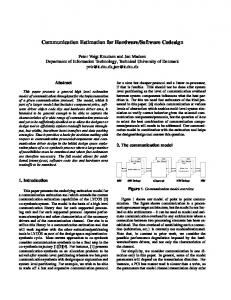
III. GENERIC ARCHITECTURE TEMPLATES One of the primary tasks in system level design is to create models representing various design decisions. The first critical design is to distribute the functionality in the specification onto components in the multiprocessor architecture, thereby requiring an architecture model to reflect that decision [24]. We use a generic multiprocessor architecture model that promotes the adaptability for multiprocessor SoC design and the possibility of an automatic generation of the final architecture. The model is made of a set of processors communicating through a communication network (Figure 1). The components of our architecture model belong to the three essential categories: software, hardware, and communication components. They consist of CPUs, hardware blocks (IPs), memories, and communication interfaces. Several kinds of CPUs may be used within the same design. The addition of an extra CPU requires the availability of a set of tools (ISS, compiler, debugger, etc.) and models (layout, timing, operating systems, etc.). The communication network may be of whatever complexity from a single bus to a network with T1 T2 T3
OS
Mem
CPU
Tn AD
Application-specific coprocessors (DCT, Viterbi, etc.)
IPs (Memory, etc.)
Com. Com. coprocessors coprocessors
Com. Com.
Component Adapter Internal bus
Com. Com. coprocessors coprocessors
Communication Communicationnetwork network
Fig. 1. Generic multiprocessor architecture model
Channel Adapter #1
CA #n
INTERNATIONAL JOURNAL OF EMBEDDED SYSTEMS, VOL. 1, NO. 12, SEPTEMBER 2004
Mem. controller
ARM7 Core
Mem. controller
Comm. Interface
DSP Core
(Nprocessors)
Comm. Interface
Mem. controller
Component local bus
ARM7 Core Comm. Interface
Point-to-Point Network
Ext_in
3
Component Specific
Component Adaptor
Ext_out
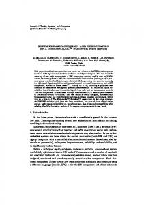
Fig. 2. Instance of multiprocessor architecture platform
complex protocols [40]. Processors are linked to the common network through communication interfaces. In order to dissociate processors from the communication network, generic communication interfaces are used. They are composed of two parts; one specific to the processor (interfacing its bus), and the other is generic and depends on the number of communication channels and communication protocols used. The communication software is closely linked with the hardware communication controllers. Moreover, we may provide several hardware/software tradeoffs of the communication protocols without altering the communication programming interface. The architecture model we propose is modular flexible and scalable. Modularity is obtained thanks to communication interface that allows the separation between modules behavior and the on chip communication network. The flexibility which is defined as the facility to adapt to new requirements imposed by designer, user or technology is due to the use of generic models and modularity. The scalability which is defined as the ability for incremental addition of components is also due to the modularity and the systematic assembling scheme. This gives the possibility to design separately each part of the application; we can even include pre-designed modules (IPs). Figure 2 shows a typical instance of this platform made of N processors. The communication network is a point-to-point network. The choice of the processors was based on availability. These were the only two processors we had access to when we started this project. The current version of this work makes use of ARM7 and 68000 CPUs. Of course the addition of new CPUs will not change the principle of the approach. The architecture platform parameters that can be configured by the designer are the number of CPUs, the memory sizes for each processor, I/O ports for and interconnections between processors, the communication protocols and the external connections (peripherals). These parameters show the scalability of the platform and enable the design of application-specific architectures of different scales. The communication interface depends on the processor attributes and on the applicationspecific parameters (communication structure). In fact, the communication interface that we use to connect the processor to the communication network, is composed of two parts; one specific to the processor (interfacing its bus), and the other is generic and depends on the number of communication channels and communication protocols used. Figure 3 shows a
Internal comm. Bus
Application/Network Specific
Channel Adaptor #1
Channel Adaptor #n
Communication Network
Fig. 3. Generic model of a communication coprocessor interface
generic model of a communication coprocessor interface. This decomposition in two parts allows dissociating the CPU from the communication network. Each interface module acts as a coprocessor for the corresponding CPU. The application dependent part may include several communication controllers managing the communication through parallel channels. The arbitration is done by the CPU-dependent part. The overhead induced by this communication coprocessor depends on the design of the basic components and may be very low. As it will be explained later, the use of this architecture for interfaces provides huge flexibility and allows for modularity and scalability. Additionally, this model allows adapting the heterogeneous features of processor to the communication network and enabling easy implementation of different protocols (e.g. multi-master bus, broadcasting, etc.). IV. GAM-SOC METHODOLOGY AND FLOW We represent the system with a hierarchical network of modules. A module consists of behavior and port(s), i.e. behavior and communication are separately described. Modules are connected with each other by connecting their ports via communication channels (in short, channels). We use a wrapper when the module has different communication behavior (e.g. different communication protocol) than the communication channel(s). Thus, system level channels provide only two kinds of functions, send and receive for the ports to access them. At the macro-architecture level (i.e. transaction-level modeling), each channel is given its own communication protocol (e.g. FIFO, handshake, etc.) and parameters (e.g. FIFO size). Macro-architecture level channels provide protocol-specific functions (e.g. FIFO available, FIFO write, etc.) for the ports to access them. At the microarchitecture level, communication is represented at cycle accurate level. Figure 4 shows a simple view of
INTERNATIONAL JOURNAL OF EMBEDDED SYSTEMS, VOL. 1, NO. 12, SEPTEMBER 2004
Channels
Wrapper
4
Fixed param.
M1
M3
(a)
Application
Arch. Platform
•Network type •Memory Arch. •CPU types
system level description
(user constraints)
M2
Module
µP
Micro-architecture Generation IP
M1 M1
(b)
•Nb. of CPU •Comm. Prtocls. •Memory size •I/O for each CPU •Processors interconnects •External I/O
Param. Choice
Pr. Attributes Library
(Adr. & Rsrces.)
Archi. Design
Comm. I/F Library
Detailed Archi.
M3
OS
Alloc. Table
Abstract Archi. Descrp.
Software Adaptation Binary Code
CC
for each Pr
CC Communication Network
Pr. & Mem. Simulators
Pr. & Mem. Cores
SoC synthesis
Fig. 4. Multiprocessor SoC architecture generation scheme
multiprocessor SoC architecture generation. In our flow, architecture generation means implementing wrappers and communication channels from a macro-architecture down to a micro-architecture. The overall GAM-SoC flow is shown in figure 5. In this model, the application-specific parameters are used to configure the architecture platform and an application-specific architecture is produced. These parameters result from an analysis of the application to be designed. Starting from a high-level model of the application at the system level (parallel communicating processes), and considering one multiprocessor architecture platform, the designer has to choose the adequate parameters of his final architecture. In this choice, the functional and non-functional constraints must be taken into account. A hardware/software codesign tool or a performance estimation tool can be used to assist the designer in his choice [2] [23]. The parameters that must be fixed in this step are the number of CPUs (of each available type), the memory sizes for each processor and the size of the shared memory if needed, I/O ports for each processor and interconnections between processors, the communication protocols and the external connections (peripherals). The results of this stage are two elements: an abstract architecture description and an allocation table. The abstract architecture constitutes the skeleton of the final SoC. It is an instance of the architecture platform and contains all the application specific parameters. The allocation table contains all the information about the memory map, the memory addresses and the interruption levels reserved for each CPU. Writing the allocation table requires a deep knowledge of the processors attributes (i.e. address space, interrupts levels). The architecture design step makes use of the allocation table to refine the abstract architecture and to produce the detailed architecture. The main action here is the design of the communication network including the processor communication interfaces. The software-adaptation step produces the programs which will run on each CPU. This may be a quite sophisticated step for large applications. This is true
SoC Validation by cosimulation
Fig. 5. Multiprocessor SoC design flow
especially when an operating system is required to run the software [8], [21], [38]. This step is out of the scope of this paper. The allocation table which was used to configure the communication interfaces may be used for the software adaptation, for memory mapping and addresses allocation (I/O ports, interruptions). The results of this step are the binary codes that must be loaded onto the memory of each processor. Of course, the operation of software adaptation is done separately for each processor. For the SoC validation, we need a cycle-accurate executable architecture that can run the application. To that end, we used a cosimulation approach [17] where CPUs are replaced by cycle accurate ISS and bus functional models. All other parts of the architecture are modeled in VHDL-RTL and executed by a VHDL simulator (e.g. Synopsys VSS [46]). Further illustrations about the validation of this flow will be given in the next section through a demonstration example.
V. DESIGNING AN APPLICATION-SPECIFIC SOC ARCHITECTURE FOR A PACKET ROUTING SWITCH
In order to illustrate the efficiency of the proposed architecture model and design flow, we detail in this section the design process of a packet routing switch [43]. The packet routing switch constitutes a powerful solution for large-frame or cell-switching systems [43]. The version we present here consists of two input controllers and two output controllers. Each of the controllers handles one communication channel.
C h _ o u t_ 1
O u tp u t C o n tr o lle r 1
In p u t C o n tr o lle r 1
C h _ in _ 1 M ode
C h _ o u t_ 2
O u tp u t C o n tr o lle r 2
In p u t C o n tr o lle r 2
Fig. 6. Block diagram of the packet routing switch
C h _ in _ 2
INTERNATIONAL JOURNAL OF EMBEDDED SYSTEMS, VOL. 1, NO. 12, SEPTEMBER 2004
5
TABLE I
A4-processor architecture description for the packet routing switch Modules
Memory size
CPU
Input Controller 1 (IC1)
ARM7 40 MHz
ROM (10 KB) RAM (20 KB)
Input Controller 2 (IC2)
ARM7 40 MHz
ROM (10 KB) RAM (20 KB)
Output Controller 1 (OC1) Output Controller 2 (OC2) External Environment (Periphs.)
MC68000 20 MHz
ROM (20 KB) RAM (20 KB)
MC68000 20 MHz
ROM (20 KB) RAM (20 KB)
VHDL process 100 MHz
Comm. channels Ch_in_1 Mode IC1 ⇒ OC1 IC1 ⇒ OC2 Ch_in_2 Mode IC2 ⇒ OC2 IC2 ⇒ OC1 Ch_out_1 IC1 ⇒ OC1 IC2 ⇒ OC1 Ch_out_2 IC2 ⇒ OC2 IC1 ⇒ OC2 Ch_in_1 Mode Ch_in_2 Ch_out_1 Ch_out_2
Comm. Protocols FIFO at transmitter with HSK FIFO at transmitter with HSK FIFO at transmitter with HSK FIFO at transmitter with HSK FIFO at transmitter with HSK
Buffer size (HW) 0 0 128 Bytes 128 Bytes 0 0 128 Bytes 128 Bytes 0 0 128 Bytes 0 0 128 Bytes -
Interrupts IRQ* IRQ* IRQ* IRQ* Level 5 Level 6 Level 5 Level 6 -
Addresses 0x7000 0x7004 0x7008 0x700C 0x7000 0x7004 0x7008 0x700C 0x9000 0x9002 0x9004 0x9000 0x9002 0x9004 -
a
The address of the communication controller that requested the interruption will be delivered by the communication interface to the CPU when access is performed at the address 0x7100.
The communication links between input and output controllers are configured by an external signal to be direct or switched. Figure 6 shows the block diagram of the packet routing switch. A. Parameters extraction From this specification we can note that we have 4 communicating modules, 4 internal communication channels and 5 external links. We know also that the input frame is 128 bytes long. The application was specified in the SystemC language. Thus, in order to implement this application on the proposed architecture platform, we started by choosing the application-specific parameters and writing (as result) the allocation table and the architecture description. We chose 4processor architecture as a first implementation. Table 1 shows the details of all the chosen parameters. In this table, each line contains the specific parameters of one module (processor) of the architecture. For example, in the first line we see that the IC1 module will be implemented on an ARM7 processor running with a 40 MHz clock frequency. The local memory size for this module was chosen approximately (after a first pre-compilation of the software part). There are 4 communication channels in this module, and the communication protocol used for all of them is a FIFO protocol with handshaking. The three last columns depend on the chosen communication protocol. We can see that in this communication protocol, the FIFO is placed at the output channel and its size is equal to the transmitted frame size. For input channels (Ch_in_1 and Mode), the communication is done by interrupts; we use in this module the IRQ interrupt of ARM7 processor. In the last column of the table, we reserved the global addresses for the communication channels. This table will be used for the configuration of the communication interfaces and for the software adaptation (see figure 5).
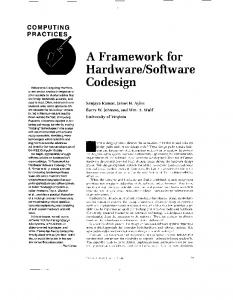
B. Architecture design As the architecture contains 4 CPUs, 4 communication interfaces must be designed. The interfaces of figure 3 are modeled in VHDL-RTL as a generic component that needs to be personalized according to the application. So, for each of the 4 communication interfaces we analyze the parameters of table 1, and modify the VHDL files to obtain the specific interface. For example, in order to design the communication interface of the first module (IC1), the interface controller of ARM7 was selected and 4 communication controllers were instantiated (2 input controllers and 2 output controllers). The chosen communication controllers correspond to handshake protocol with buffering at the transmitter side. The size of the buffer was configured to 128 bytes (see table 1). The memory addresses of the communication controllers are also configured to the values mentioned in table 1. These addresses are also used to configure the address decoder which enables the corresponding communication interface (i.e. external accesses of the CPU). The result of this stage is a VHDL component which represents the specific communication interface of the first module (IC1). Figure 7 shows the block diagram of this interface. We notice that input communication controllers use interrupts to communicate data to the CPU, so the interrupt controller must be configured to use the IRQ interrupt of the ARM7 as mentioned in table 1. In the same way we constructed the 3 other communication interfaces. As all of these interfaces are VHDL components, we chose to gather all of them with the communication network (point-topoint connections) in one VHDL block. Table 1 is also used at this stage to determine the links between the 4 interfaces and their external links with the environment. In this example, the environment was a simple test bench which sends and receives the data packets; it was written in VHDL and uses the same
INTERNATIONAL JOURNAL OF EMBEDDED SYSTEMS, VOL. 1, NO. 12, SEPTEMBER 2004
Communication I/F CPU Memory Bus Adapter
0x7000
Controller_in (FIFO+HSK) F1
F2
Req Ack
Ch_in_1
Data
6
MC68k ISS
MC68k ISS
ARM7 ISS
ARM7 ISS
(OC2)
(OC1)
(IC2)
(IC1)
Mem. BFM
Mem. BFM
Mem. BFM
Mem. BFM Clk4
Clk3
Clk2
F3
ARM7 Core (IC1 Module)
RESET_n FIQ_N WAIT_N _N ALE RW _N BW_N M[4:0] DATA DOUT ADRESSE
F1
F2
F3
0x7004
F5 F7 F6
Adr. Decoder
Controller_in (FIFO+HSK) F1
F4
IT Controller
D A T A
Clk1
cosimulation bus (SystemC)
F2
Req Ack
Mode
Data
F3
0x7008
B U S
F1
F3 Req Ack
FIFO
0x700C
Data
F2
FIFO
mode Cin1
Env. (Test bench)
VHDL
Fig. 8. 4-processor cosimulation architecture of the packet routing switch
Clk F4
Cin2
Cout2 IC1 ⇒ OC1
Controller_out (FIFO+HSK) F1
OC1 ⇐ IC1 Cout1
F2 F4
Channel Controller
OC1 ⇐ IC2
OC2 ⇐ IC2 OC2 ⇐ IC1
Controller_out (FIFO+HSK)
F3 Req Ack
IC1 ⇒ OC2
Data
Fig. 7. Communication Interface of IC1
communication protocol as mentioned in table 1. C. Software adaptation We wrote simple test programs to run on each of the 4 processors. Each program makes use of read/write functions. An output operation corresponds to writing the corresponding data at the right address. For example, in module IC1, to transfer the received packet to module OC1 the packet is written (byte by byte) on the global address 0x7008. The communication interface buffers this data and takes charge of its transfer to module OC1. Input operations use interrupt events and require interrupt handlers. For example, for the IRQ handler of IC1 module, the CPU starts by performing a read access at the address 0x7100. When accessing this address, the interface delivers the address of the corresponding communication controller which requests the interrupt (0x7000 or 0x7004), and then the data is read at this received address. Note that this way of interrupt vector is very useful when the number of the input communication controllers is greater than the available interruption levels of the CPU. In this example, the data packet was received byte by byte. These test programs were compiled and linked with the corresponding boot code for each CPU (to initialize the RAM/ROM, stacks, vectors, interrupts…). The results of this step are the binary codes that must be loaded onto the ROM of each processor. D. Architecture validation In order to validate the generated architecture, we use a cycle accurate cosimulation approach based on SystemC [10, 21]. In this approach, CPUs are replaced by cycle-accurate ISSs and bus-functional models. With this cosimulation tool we already have two cycle-accurate simulators; one for ARM7 (based on ARMulator) [41] and the other for M68000. In addition, with these simulators, local memories are modeled in software as a part of the ISS, and the access to those memories is cycle accurate. Communication interfaces, communication
network and the external environment (the test bench) were modeled in VHDL-RTL (cf. section B). The VHDL part is executed by a VHDL simulator (e.g. VSS). We constructed the cosimulation environment which consists of 2 ARM7 ISS, 2 M68000 ISS and one VSS. Figure 8 shows the schema of the generated cosimulation environment. The cosimulation bus is based on SystemC and ensures the interconnection and synchronization of the running simulators (shared memory and monitors) for coherent execution of the overall system [31]. The binary codes were loaded onto the corresponding ISS and the VHDL block was loaded onto the VSS.
VI. EXPERIMENTAL RESULTS AND EVALUATION OF OUR TARGET DESIGN FLOW In order to analyze the efficiency of our approach, we have used 3 other designs based on this generic architecture platform: packet routing switch, IS-95 CDMA, and VDSL Modem. A. Packet routing switch A 2-processor implementation of the packet routing switch was also realized following the same flow. Only two CPUs are used: the two modules IC1 and IC2 are implemented on one ARM7 CPU, and the two other modules (OC1 and OC2) are implemented on one M68000 CPU. Therefore, only two communication interfaces had to be designed. These communication interfaces differ from the ones developed in the previous architecture by the number of communication controllers. So while building the communication interface of the ARM7 CPU, 7 communication controllers were instantiated (3 input and 4 output controllers). We modified the test programs to adapt them to this new architecture, and we validated the system by cosimulation. In order to compare the 2 architectures, we synthesized the VHDL blocks corresponding to the interfaces for the two architectures. The synthesis results of the two architectures are shown in table 2. In both cases, the biggest part of the area is used for CPUs and memories. The additional logic amounts only to 5156 gates for the 4-processor architecture and 3376 gates for the 2processor architecture. In both cases this represents less than
INTERNATIONAL JOURNAL OF EMBEDDED SYSTEMS, VOL. 1, NO. 12, SEPTEMBER 2004
TABLE 2 SYNTHESIS RESULTS OF THE TWO ARCHITECTURES IMPLEMENTING THE PACKET ROUTING SWITCH
Architecture
v o c_ tx
4-processor Architecture
2 ARM7 Cores 2 M 68000 Cores
5156 Gates + 6 FIFOs of 128 bytes
2-processor Architecture
1 ARM7 Core 1 M 68000 Core
3376 Gates + 6 FIFOs of 128 bytes
B. IS-95 CDMA: Analyzing of the design cycle We designed an IS-95 CDMA protocol to analyze the duration of the design cycle. This experiment has shown that a multiprocessor architecture can be designed in about one week when all the components of the architecture platform are ready. Figure 9 shows the block diagram of the system. In an IS-95 CDMA cellular phone system, the mobile station contains two CDMA baseband modems (Tx and Rx), a QCELP (Qualcomm Code Excited Linear Prediction) voice encoder (ENC) and decoder (DEC), and a call processor (CAP). In the forward traffic channel, the input frame (on voice_in channel) is 160 bytes long, the encoded frame is 44 byte, and the transmitted frame is 1536 byte. Although, many architectural solutions are conceivable, we chose to map this application on the same 4-processor architecture as the one used to implement the packet routing switch (we did not implement the call processor – CAP). In order to do that, we wrote the allocation table and the architecture description for the IS-95 CDMA application. Comparing with those of the packet routing switch, the communication architecture is slightly different. Also the FIFOs sizes in the communication controllers are different. Thus, we re-built the 4 new communication interfaces. Moreover, as a C++ version of the application was available, we prepared the 4 software CDMA baseband signal CDMA baseband signal
Modem: Rx A
B
C
DEC
CAP
Modem: Tx D
E
F
Voice_out
ENC Voice_in
Fig. 9. Block diagram of the IS-95 CDMA mobile station
dial pad display panel
M C 68k IS S M e m .
M em .
BFM
re v _ re c
BFM
C lk
C lk
VSS a lig n
C lk
5% of the total chip area. The size of the memory used for communication remains the same for both architectures. In this case, the biggest difference comes from the area used for embedded CPUs (2 instead of 4). As expected, the cosimulation has shown that the throughput of the 4-processor architecture is twice as large as the 2-processor solution. This example shows clearly the scalability of this model. This was obtained thanks to the flexibility of the communication interface and the modularity of the approach. Additionally, the approach takes advantage of derivative designs.
re v _ tra
ARM7 IS S
s p e e ch in
Comm. I/F & Comm. Network
Processor Cores
7
s p e e ch o u t
C lk
BFM
IS S M e m . ARM7
BFM
IS S M e m . M C 68k
fo r_ tra
fo r_ re c
v o c _ rx M o b ile S ta tio n
B a s e S ta tio n
Fig. 10. 4-processor cosimulation architecture of the IS-95 CDMA
programs that will run on the 4 CPUs and generated the corresponding binary codes. Figure 10 shows the cosimulation architecture we used to validate the application on its specific designed architecture. External modules –base station and user input/output– were modeled in SystemC. Table 3 gives the time needed to fit the IS95-CDMA application on the proposed multiprocessor platform using a 4-processor implementation. We have measured the time needed for each step of the generation flow of figure 5. We noticed that the time for manual generation depends on the number of processors (four in this example), it is a linear function with slope 8 hours/processor. In fact, the manual generation is not only time consuming but also fastidious, as complex applications are still difficult to handle without tools assistance. It is worth noting that we assume that the designer has a good knowledge of the processors tool kits and the application when doing the manual generation. Otherwise you would have to add the time required to acquire this knowledge. In an automatic generation scheme, this knowledge will not be required though. The software adaptation step includes only system call insertion in an existing software code. TABLE 3 TIME NEEDED TO FIT THE IS95 CDMA ON THE MULTIPROCESSOR PLATFORM Architecture 4-processor Architecture
Operation
Time needed (Manual coding)
Param. Extrat. (including arch. description and allocation table)
~ 2hr x 4
Architecture Design and refinement
~ 2hr x 4 + 2 hr
Software design and adaptation
~ 4hrx 4
Build the cosimulation environment
~8 hr
Total
~ 42hr
INTERNATIONAL JOURNAL OF EMBEDDED SYSTEMS, VOL. 1, NO. 12, SEPTEMBER 2004
8
Host PC
M2 PC I/F
DPRAM
VOC bytes octets
ARM7
Synchro
CPU1
DSP
Config
MCU
RAM
(running a
DSP
commercial embedded OS)
Analog Front(Copper line) End
Analog Frontend BL-M
VDSL Modem Processor
VDSL Protocol Processor I-M
FPGA BL-M: bit-loading memory V-M: variance memory
Di-M
Part redesigned using GAM-SoC
Fig. 11. Block diagram of the VDSL
C. VDSL Modem: Integrating the pre-designed Hardware IP-blocks The design we present in this section concerns the implementation of a VDSL modem using our GAM-SoC methodology. The main motivation of this experimentation is to show how our GAM-SoC supports the different kind of onchip communication networks and the integration of predesigned hardware blocks (IP’s) and favors reuse. The block diagram for the VDSL modem is shown in Figure 11. The subset that we used in this experiment is shaded in Figure 12. We chose to map this part of the VDSL on two processors and hardware IP-Block architecture. The hardware IP-Block implements the TX- Framer (datapath) and it is described at RTL. The two processors (ARM7TDMI) execute parallel tasks. The control over the three modules of the specification is fully distributed. In the experiment, we used two target multiprocessor SoC architectures: one with point-to-point interconnection link (Figure 13) and the other with an on-chip shared bus (Figure 14). The architectures design and validation of the VDSL was also realized following the same flow. 1) VDSL microarchitecture with application specific point-to-point on-chip communication network Figure 13 shows the top level of the model hierarchy: the two CPUs with their local memory, address decoder, and software/hardware wrappers, the hardware IP-Block (ASIC/FPGA block on the right side) and the structure of the software and hardware wrappers. The on-chip communication
Gates
Area (mm2²) (AMS CUP 0,8µ)
Critical path delay (ns)
I/F ( M2)
3795
1,11
6,16
I/F (M3)
3284
0,96
5,95
Comm. I/F
RTL code (VHDL)
2168 lines
TX_Framer
ATM Layer
ATM Layer
I: interleaver memory Di-M: de-interleaver memory
TABLE 4 SUBSET VDSL DESIGN: INTERFACES SYNTHESIS (POINT-TO-POINT COMMUNICATION NETWORK)
Hardware blocks
TX_Framer
Fig. 12. Block diagram modified of the VDSL
FPGA
V-M
Constellation Processor
ASIC Digital Front-end
M1
CPU2
twisted-pair
Twisted-Pair (copper line)
ARM7
architecture is a point-to-point network. Each CPU is isolated through a hardware wrapper. It contains an ARM7 module adapter that bridges the ARM7 local bus to the internal wrapper bus. Comparing with the processors, the integration of pre-designed hardware blocks (IP’s) is slightly different. Since the IP block was initially described at the RTL, it does not require wrappers (thanks to point-to-point link). Additionally, the application includes some multi-point communication channels requiring sophisticated protocols. The wrapper bus connects all hardware communication adapters for each channel in the architecture. The software wrapper represents two software parts: API (Application Programming Interface), and HAL (Hardware Abstraction Layer) [38]. Tasks running on the ARM7 processors access to the hardware wrappers only by making system calls to the communication API. The HAL is the low-level code such driver devices, In/Out, ISR, etc. that manages direct access to the communication adapters. In this architecture, all three modules
act as masters when interacting with their environment. The synthesis results of the subset VDSL architecture are shown in table 4. The result was obtained by instruction set simulator (ISS) execution. That of hardware-IP block was obtained by VHDL simulator execution. Table 3 shows the numbers obtained after synthesis of the hardware wrappers of CPU1 and CPU2 in AMS 3.20 (0.8µm) technology. These results are good since they account for less than 5% of the total system surface and have a critical path that corresponds to less than 15% of the clock cycle for the 40 MHz ARM7 processor used in this case study.
2) AHB-AMBA- based Multiprocessor architecture for VDSL (Figure 14) In the previous sections, we have described the point-topoint interface for connecting SoC components (processors, hardware IP-blocks, memories, etc.) together in a common and easily reusable way. But for to be able to integrate these components to an existing on-chip bus such as the widely used AHB-AMBA developed by ARM [41], [44], [47], a special kind of interface wrapper is required [15]. The communication interface that we use to connect the processor to the communication network, is composed of two independent parts; one specific to the SoC component (interfacing its bus), and the other is specific to an existing on-chip bus. Thus, in order to implement this application on multiprocessor SoC architecture with an on-chip shared bus such as AHB-AMBA, we started by using the new multiprocessor platform instance based on AHB and by choosing the application-specific
INTERNATIONAL JOURNAL OF EMBEDDED SYSTEMS, VOL. 1, NO. 12, SEPTEMBER 2004
T1
T2
T3
T1
T2
T3
T1
API
API
M1 Memory (RAM/ROM)
Address decoder
Memory (RAM/ROM)
...
HW wrapper
.
.
Wrapper bus
HAL
Memory (RAM/ROM)
Address decoder
CA
M3
M2 ARM7 processor core
Memory (RAM/ROM)
Address decoder
IP (ASIC/FPGA)
reset clock
...
HW wrapper
ARM7 processor adapter
ARM7 local bus
A7Wrap
ARM7 processor adapter
IP-block adapter
Master I/F AHB
Slave I/F AHB
Master I/F AHB
FIFO CA
.
...
Polling CA CA
T3
.
FIFO 3 CA
.
...
FIFO 1 CA
..
FIFO 3 CA
.
.
FIFO 1 CA
.
.
CA
T2 API
ARM7 local bus
ARM7 processor adapter
TIMER
Wrapper bus .
test vector
ARM7 processor core
ARM7 local bus
ARM7 processor adapter
HW wrapper
T1
M1
IP (ASIC/FPGA)
Address decoder
reset clock
ARM7 local bus
T3
HAL
M3
M2 ARM7 processor core
T2 API
HAL
HAL
ARM7 processor core
9
AHB AMBA BUS
...
Fig. 14. AHB-AMBA- based Multiprocessor architecture for VDSL Fig. 13. VDSL microarchitecture with application specific point-to-point on-chip communication network
parameters and writing (as result) the allocation table and the architecture description. Note that the on-chip communication bus and/or processing components can be described at several levels of abstraction (e.g. transaction level modeling [10]). The wrappers implement protocols conversions between different abstraction levels. The architecture design step makes use of the allocation table to refine the abstract architecture and to produce the detailed architecture. The main action here is the refinement of hardware/software wrappers (Figure 14). D. Results Analysis These examples illustrate the feasibility and the efficiency of our GAM-SoC methodology and an associated generic model. With this model, multiprocessor architectures become much easier to handle. We illustrated how the generation of application-specific architectures can become systematic and very fast. Note that the architecture model we propose in this paper is far more generic than the architecture platform we used for the examples. This leads obviously to a huge application field. Other kinds of CPUs (and DSP cores) can be integrated and used in the same way. This shows the great flexibility and modularity of the proposed architecture model. The modularity of our architecture model appears in the organization scheme, which consists of separated modules communicating through a communication network. It separates the behavior from the inter-sub-systems communication. In addition, each module can be designed separately, an assembling scheme is provided to connect them efficiently and to enable the reuse of existing modules. This assembling scheme is quite structured and easily permits the reconfiguration of the architecture. Thus, the technology choice can be done late in the design process which leads to a great flexibility. The scalability of our architecture model is also achieved thanks to the assembling scheme. It depends on the scalability of the chosen communication network. This scalability allows adapting the proposed architecture model to applications of different complexity scales, for instance increasing the number of processors or communication buses.
VII. CONCLUSION In this paper, we have presented a generic architecture model for application-specific multiprocessor system-on-chip design. The proposed model is modular, flexible and scalable. It permits a systematic generation of multiprocessor architectures for embedded systems-on-chip. This work is a promising step towards the definition of an efficient multiprocessor SoC design environment applicable to a large application domain. This paper focused on the definition of the architecture model and a systematic design flow that can be automated. The feasibility and effectiveness of this architecture model were illustrated by design examples showing the effectiveness of the model. We have also demonstrated that the use of such a model shortens significantly the design cycle of complex applications.
ACKNOWLEDGEMENT The authors would like to acknowledge their many colleagues at SLS group from TIMA laboratory for their input on various topics presented in this paper.
REFERENCES [1] [2]
[3] [4] [5] [6] [7] [8] [9]
S. Antoniazzi, et al., “Hardware/Software codesign for embedded telecom systems”, in ICCD'94, October 1994. A. Baghdadi, et al., “Combining a performance estimation methodology with a hardware/software codesign flow supporting multiprocessor systems”, IEEE Transactions on Software Engineering, vol. 28, No. 9, September 2002 pp. 822-831. A. Baghdadi, et al., “An Efficient Architecture Model for Systematic Design of Application-Specific Multiprocessor SoC”, in DATE’01, March 2001. F. Balarin, et al., Hardware-Software Co-design of Embedded Systems – The POLIS Approach, Kluwer Academic Publishers, 1997. R.A. Bergamaschi, and W.R. Lee, “Designing Systems-on-Chip Using Cores”, In DAC’00, June 2000. J-Y. Brunel, et al., “COSY Communication IP's”, In DAC, June 2000. P.H. Chou, et al., “The Chinook Hw-Sw co-synthesis system”, In ISSS’95, September 1995. W. Cesario, et al., “Component-based design approach for multi-core SoCs,” in DAC’02, June 2002. D. Culler et al., Parallel Computer Architecture: A Hardware/Software Approach, Morgan Kaufmann Publishers, August 1998.
INTERNATIONAL JOURNAL OF EMBEDDED SYSTEMS, VOL. 1, NO. 12, SEPTEMBER 2004
[10] L. Cai and D. Gajski, “Transaction Level Modeling: An Overview” in ISSS-CODES’03, October 2003. [11] W. Dally and B. Towles, “Route Packet, not wires: on-chip interconnection networks,” in DAC’01, June 2001. [12] L. De Alfaro and T. Henzinger. “Interface theories for component-based design. In EMSOFT’01, Springer-Verlag, 2001, pp. 148-165. [13] G. De Micheli, “Computer-aided hardware-software codesign”, IEEE Micro, 14(4):10-16, August 1994. [14] J. Fu, et al., “A Java-Based Distributed System Framework for RT Development” in ICDCS Workshop on Distributed RT Systems 2000. [15] M. Gasteier, M. Glesner, “Bus-based communication synthesis on system-level,” ACM Trans. on DAES, Vol4, No1, 1999. [16] M. Genoe, et al., “Experiences of IP Reuse in System-on-Chip Design for ADSL”, In ISSCC’99, February 1999. [17] P. Gerin, et al., “Scalable and Flexible Cosimulation of SoC Designs with Heterogeneous Multiprocessor Target Architectures”, In the ASPDAC’01, January/February 2001. [18] R. Gupta and G. De Micheli, “Specification and Analysis of Constraints for Hw-Sw Co-synthesis”, IEEE Trans. on CAD, March 1997. [19] R. Gupta and Y. Zorian, “Introduction to Core-Based Design”, IEEE Design and Test of Computers, October 1997. [20] P. Hsiung, T. Lee and F. Su: Formal Synthesis and Code Generation of Real-Time Embedded Software using Time-Extended Quasi-Static Scheduling. APSEC’02. [21] A. Jerraya et al., Embedded Software for SoC", Kluwer Academic Publishers, October 2003. [22] P. Knudsen and J. Madsen, “Integrating Communication protocol selection with Hw/Sw codesign” in IEEE Trans. on CAD, August 1999. [23] K. Lahiri, et al., “System-level performance analysis for designing onchip communication architecture,” in IEEE Trans. on CAD, June 2001. [24] C. Lennard, et al., “Standards for System-Level Design: Practical Reality or Solution in Search of a Question”, In DATE’00, March 2000. [25] J. Madsen, et al., “YCOS: the Lyngby Co-Synthesis System”, DATE’97, March 1997. [26] J. Notbauer, et al. “Verification and Management of a Multimillion-Gate Embedded Core Design”, in DAC’99, June 1999. [27] R. Ortega and G. Borriello, “Communication synthesis for distributed embedded systems,” in ICCAD’98, 1998. [28] A. Österling, et al., Hw/Sw Codesign: Principles and Practice, Chapter: The COSYMA System, Kluwer Academic Publishers, 1997. [29] D. Patterson and J. Hennessy, Computer Organization and Design: The Hw/Sw Interface, Second Edition, Morgan Kaufmann Publishers, 1997. [30] A. Sangiovanni-Vincentelli, et al., “Formal Models for Communicationbased Design”, Proceedings of CONCUR '00, August, 2000. [31] L. Semeria and A. Ghosh, “Methodology for Hardware/Software Coverification in C/C++”, in ASP-DAC’00, January 2000. [32] K. Van Rompaey, et al., “CoWare –A Design Environment for Heterogeneous Hw/Sw Systems”, in EURO-DAC’96, September 1996. [33] S. Vercauteren, et al., “Constructing Application-Specific Heterogeneous Embedded Architectures from Custom Hardware/Software Applications”, In DAC’96, June 1996. [34] K. Wakabayashi, and T. Okamoto, “C-Based SoC Design Flow and EDA Tools: An ASIC and System Vendor Perspective”, IEEE Transactions on CAD of ICS, Vol. 19, No. 12, December 200. [35] W. Wolf, “How Many System Architectures”, IEEE Computer 2003. [36] W. Wolf, “A Decade of Hw/Sw Codesign”, IEEE Computer 2003. [37] T. Yen and W. Wolf, “Communication synthesis for distributed embedded systems”, in ICCAD ’95, 1995. [38] S. Yoo, and A. Jerraya, “Introduction to Hardware Abstraction Layers” for SoC. DATE’03, March 2003. [39] N. Zergainoh, et al., Framework for System Design, Validation and Fast Prototyping of SoCs", chapter in Architecture and Design of Distributed Embedded Systems", Kluwer Academic Publishers, April 2001. [40] X. Zhu and S. Malik, “A hierarchical modeling framework for on-chip communication architectures”ICCAD’02, 2002. [41] ARM, Inc. AMBATM, Available: http://www.arm.com/. [42] Cadence Inc., VCC available at http://www.cadence.com. [43] IBM, Packet Routing Switch, Available: http://www.chips.ibm.com/ [44] CoreConnectTM Bus, Available: http://www.chips.ibm.com/ [45] MAJCTM, Available: http://www.sun.com/microelectronics/MAJC/ [46] VHDL System Simulator, http://www.synopsys.com/products/ [47] Sonics, Available: http://www.sonicsinc.com/. [48] VSI Alliance™, Available: www.vsi.org/resources/techdocs/vsi-or.pdf.
10
[49] O. Gangwal et al., “A Scalable and Flexible Data Synchronization Scheme for Shared-Memory Systems”, in ISSS’01, October 2001.
Nacer-Eddine Zergainoh received state engineering degree in electrical engineering from National Telecommunication School and the M.S. and Ph.D. degrees in Computer Engineering from University of Paris XI, in 1991 and 1996 respectively. Currently, he is an associate professor at the University of Joseph Fourier, Grenoble, and member of the research staff of the Techniques of Informatics and Microelectronics for Computer Architecture Laboratory, Grenoble. Prior to that, he was R&D Engineer at ILEX-Computer Systems, in Paris, France. His current research interests are hardware/software codesign, high-level synthesis and CAD issues for realtime digital signal processing, design and exploration of application-specific multiprocessor SoC (including design and analysis of on-chip communication architectures, network on-chip issues). He also maintains an active interest in parallel processing, multiprocessor architectures, and real-time operating systems. Prof. Zergainoh has served on the technical program committees for several international conferences and workshops.
Amer Baghdadi received the engineer degree in electronic engineering from the Ecole Nationale Supérieure d'Electronique et de Radioélectricité de Grenoble (ENSERG), Grenoble, France, in 1998, and the MS and PhD degrees in computer science from the Institut National Polytechnique de Grenoble (INPG), Grenoble, France, in 1998 and 2002, respectively. In 2002 he held an assistant professor position at the ENSERG while he continued his research activities with the System-Level Synthesis Group, Techniques of Informatics and Microelectronics for computer Architecture (TIMA) Laboratory, Grenoble, France. His research interests include system-on-chip design methodology, especially, design and exploration of application-specific multiprocessor architectures, performance estimation, and on-chip communication architectures. In December 2003, Dr. Baghdadi, moved to hold an associate professor position at the Electronic Engineering Department of the ENST Bretagne (Ecole Nationale Supérieure des Télécommunications de Bretagne), France.
Ahmed Amine Jerraya received the Engineer degree from the University of Tunis in 1980 and the D.E.A., "Docteur Ingénieur", and the "Docteur d'Etat" degrees from the University of Grenoble in 1981, 1983, and 1989 respectively, all in computer sciences. In 1986, he held a full research position with the CNRS (Centre National de la Recherche Scientifique). From April 1990 to March 1991, he was a Member of the Scientific Staff at Nortel in Canada, working on linking system design tools and hardware design environments. He is the General Chair of HLDVT'02 and Co-Program Chair of CASES'02. He served as General Chair for DATE 2001, ISSS'96 and General Co-Chair for CODES'99. He also served as Program Chair for ISSS'95, RSP'96 and Co-Program Chair of CODES'97. He published more than 100 papers in International Conferences and Journals. He received the Best Paper Award at the 1994 ED&TC for his work on Hardware/Software Co-simulation. Dr. Jerraya is currently managing the System-Level Synthesis group of TIMA Laboratory and has the grade of Research Director within the CNRS.