FLASH multiprocessor, we employed a hardware/software codesign .... nal interfaces the message header is passed along to the inbox, where it is pushed through a hardware dispatch table that deter- mines the ...... Field, Calif., August 1985.
Hardware/Software Codesign of the Stanford FLASH Multiprocessor Mark Heinrich, David Ofelt, Mark Horowitz, and John Hennessy In Proceedings of the IEEE Special Issue on Hardware/Software Co-design, Vol. 85, No. 3, March 1997 Abstract Hardware/software codesign is a methodology for solving design problems in systems with processors or embedded controllers where the design requirements mandate a functionality and performance level for the system, independent of the hardware and software boundary. In addition to the challenges of functional correctness and total system performance, design time is often a critical factor. To design MAGIC, the programmable memory and communication controller for the Stanford FLASH multiprocessor, we employed a hardware/software codesign methodology. This methodology allowed us to concurrently design the hardware and software thereby reducing design time while simultaneously ensuring that the design would meet ambitious performance goals. Serializing the hardware and software design would have lengthened the design time and significantly increased the amount of redesign when the tradeoffs between the hardware and software implementations became clear late in the design process. The codesign approach led us to build a series of hierarchical simulators that allowed us to begin design verification early and to reduce the level of effort required to ensure a functional design.
1 Introduction The design and verification of MAGIC, the single-chip memory and communication controller for the Stanford FLASH multiprocessor, is a classic example of hardware/software codesign. The MAGIC chip runs protocol code sequences on an embedded processor to handle all memory system references in the FLASH machine. In addition, MAGIC has very aggressive performance goals because its performance is critical to that of the overall machine. This paper describes how we used hardware/software codesign to establish the boundary between what was implemented in hardware (to enhance performance) and what was implemented in the software that runs on the embedded controller (to reduce design complexity and increase flexibility). A successful design methodology must consider design time as well as performance goals. To meet the design time goals of a large, innovative multiprocessor system with a limited number of engineers, we needed a methodology that allowed the concurrent development of the hardware, the software to run on MAGIC, the simulation environment, the software development environment, and the verification and validation tools. By structuring our simulators hierarchically, we were able to achieve this concurrency, allowing extensive high-level simulations to estimate the performance impact of different architectural alternatives, while the lower-level, more accurate simulators and the RTL were still being designed. Once verification of the actual RTL began, we maintained the ability to simulate the design at varying levels of accuracy and performance, allowing us to test different aspects of the design concurrently. This hierarchical approach trades off simulation accuracy for simulation speed, allowing us to design a high-performance, functionally correct system while maintaining a short design time. Section 2 of this paper gives some general background on the FLASH multiprocessor and the role of the MAGIC chip, as a context for the remainder of the text. Section 3 provides an overview of computer system design from high-level system simulation to low-level circuit simulation. In Section 4 we discuss the hardware/software codesign of the high-level FLASH 1
architecture, and detail the simulation techniques we adopted. Section 5 shows how the same methodology carries over into the verification and validation of MAGIC. Section 6 summarizes the major themes, and highlights the advantages that hardware/software codesign brought to the FLASH design.
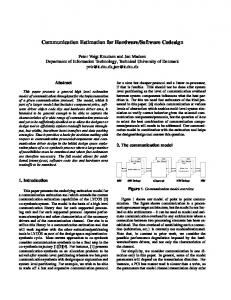
2 FLASH Architecture The Stanford FLASH multiprocessor [KOH+94] is a general-purpose multiprocessor designed to scale up to 4096 nodes. It supports applications which communicate implicitly via a shared address space (shared memory applications), as well as applications that communicate explicitly via the exchange of messages (message passing applications). Both types of communication take advantage of underlying hardware support. This support is implemented in the MAGIC chip, the communication controller and hub of a FLASH node. Rather than build the shared memory and message passing support directly into state machines in MAGIC, we embedded a programmable protocol processor in MAGIC that can run software code sequences to implement both communication protocols. Since these protocols can be quite complex, this greatly simplifies the hardware design process, and reduces the risk of fabricating a chip that does not work. A programmable protocol processor also gives us great flexibility in the types of communication protocols we can run, and allows us to debug and tune protocols or write totally new protocols even after the machine is built. 2nd-Level 2$ 2nd-Level Cache Cache
DRAM DRAM
MIPS μP R10000
Net
I/O MAGIC MAGIC
Figure 1. Stanford FLASH architecture showing the critical position of the MAGIC chip. The structure of a FLASH node, and the central location of the MAGIC chip is shown in Figure 1. The MAGIC chip integrates interfaces to the main processor, memory system, I/O system, and network with the programmable protocol processor. As the heart of a FLASH node, MAGIC must concurrently process requests from all its external interfaces and ensure that they are handled quickly enough to maintain the performance goals of the machine. Thus, its principal function is that of a data transfer crossbar connecting the various interfaces on the FLASH node. However, MAGIC also needs to perform bookkeeping to implement the communication protocol. It is the protocol processor which handles these control decisions, and properly directs data from one interface to another. In the MAGIC design we needed to control data movement in a protocol-dependent fashion without adversely affecting performance. As we will describe in Section 4.2, our initial high-level simulations concentrated on design alternatives that 2
Processor
Network
I/O
Message Split Message Split Message Data
Memory Memory
Message Headers
Data Transfer Logic
Control Pipeline
Message Combine Message Split Processor
Network
Software Queue
I/O
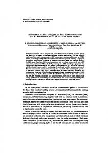
Figure 2. MAGIC Architecture showing how the programmable protocol processor handles the interpretation of messages within the control pipeline, while data transfer and the input and output functions are handled in hardware.
achieved this goal. The end result was the separation of the data-transfer logic from the control logic, as shown in Figure 2. The data transfer logic is implemented in hardware to achieve low-latency, high-bandwidth data transfers. When data enters the MAGIC chip it is placed in an on-chip dedicated data buffer and remains there until it leaves the chip, avoiding unnecessary data copying. To manage the complexity of the shared memory and messaging protocols, we implement them in software (called handlers) that runs on the embedded protocol processor. The protocol processor is a simple two-way issue 64-bit RISC processor with no hardware interlocks, no floating point capability, no TLB or virtual memory management, and no interrupts or restartable exceptions. Figure 3 shows a more detailed block diagram of the MAGIC chip. When MAGIC receives a request from one of its external interfaces the message header is passed along to the inbox, where it is pushed through a hardware dispatch table that determines the starting program counter for the appropriate handler. The protocol processor jumps to that program counter and executes the handler, which is responsible for updating any protocol state information, as well as sending other protocol messages if needed. The mechanics of any outgoing message sends are handled by the outbox. The inbox, protocol processor, and outbox thus form a control macro-pipeline, which can be operating on up to three different requests simultaneously. The control macro-pipeline lowers the request latency through the MAGIC chip and eases the burden on the protocol processor. To avoid consuming excessive memory bandwidth, protocol code is stored in an on-chip instruction cache, and data structures for the communication protocol are accessed via an off-chip data cache. Both caches are backed by normal main memory. The MAGIC chip is being fabricated as a standard-cell ASIC with the cooperation of LSI Logic. The die is 256mm2 and contains approximately 250,000 gates and 220,000 bits of memory, making it large by ASIC standards. One of our 18 on-chip memories is a custom, 6-port memory that implements 16 128-byte data buffers, the key to our hardware data-transfer mechanism. The target clock frequency for the chip is 100 MHz. The combination of multiple interfaces, aggressive macro-pipelining, and the necessity of handling multiple outstanding requests from the main processor makes MAGIC inherently multithreaded, posing complex verification and performance chal3
Processor Network I/O PI PI
Memory Memory Control Control
NI NI
I/O I/O
Software Queue Head
Inbox Inbox
ProtocolDP Processor
MAGIC MAGIC Instruction Instruction Cache Cache
Outbox Outbox
PI
NI
MAGIC MAGIC Data Instruction Cache Cache
I/O
Figure 3. High-level MAGIC block diagram, showing the control macro-pipeline. lenges. The next section discusses general approaches to designing computer systems and surveys traditional simulation tools. Section 4 and Section 5 follow with the specific hardware/software codesign methodology we followed to meet these challenges.
3 General Approaches to Computer System Design The design of a computer system must start with a specification of desired performance. For a general purpose processor, this is usually “as fast as possible” given technology or cost limitations. In an embedded system, there is usually a specific task that needs to be performed and the system performance is whatever is necessary to get that task done within a certain time constraint. Once the general system performance goal has been established, the design process works in a traditional top-down approach (as shown in Figure 4), successively increasing the level of design detail. In a computer system, the next step after setting system performance goals is determining the Instruction Set Architecture (ISA), followed closely by the design of the processor pipeline, and finally, the memory system. Once the architecture is set, the design implementation phase begins—first the RTL, then the gate-level design, and if necessary, circuit-level design. At each step in the design process, the design must be in a form amenable to simulation. Design specifications that are written, but cannot be simulated are simply too ambiguous and incomplete. The ability to simulate each level of the design is critical, since it allows both performance and correctness validation to occur at all stages of the design process. To determine overall system performance using simulation, a set of benchmarks is needed. For a general purpose computer, there are a large number of existing benchmarks such as SPEC95, NAS, Livermore Loops, STREAMS, lmbench, Linpack, and TPCA,B,C [SPEC95][NAS85][MS96][LIN88][TPC93][HP90]. A computer system targeted for a particular market segment may stress certain benchmarks over others. For example, a commercial database server will concentrate on the TPC suite which 4
Specify Functionality and Performance High-level Design [ISA] Organized Design [Pipeline and Memory System] Not OK
?
Performance Check
OK RTL
Not OK
?
Performance Check
OK Synthesis and Lower-level Design
Figure 4. Flowchart of a top-down approach to computer system design. show overall system database performance, and will probably ignore Linpack, which is purely a measure of floating point capability. Embedded systems will use the intended application as a benchmark. A microcontroller for a toaster needs to be fast enough to react to the toast-is-burning sensor before the bread is charcoal. When specifying the highest level of the system, the two main design tasks are to partition the design into major blocks and to specify the performance requirements of each block. Much of the evaluation in this phase is done with pencil and paper, since it is difficult to simulate partial or incomplete designs. Once a small number of likely design alternatives emerge, more detailed analysis is necessary. The simplest evaluation strategy is to use a spreadsheet that combines initial performance estimates for each block with event counts from a previous system or from synthetic benchmarks. This level of analysis points out bandwidth and latency problems, and validates the performance targets of each system partition. After the system has been partitioned, and the general performance targets for the processor have been determined, the next step is to specify the ISA. After choosing an initial set of instructions, the designer can write critical sections of code and crit-
5
ical loops of code (by hand at this point) to ensure that the ISA meets its performance goals. The next step is to run real benchmarks on a simple simulator that assigns fixed latencies to all instructions [Smith91][BL94]. To get accurate results, there should be code generation tools available at this point. If they are not available, then both the number of different benchmarks, and the ability to simulate design space alternatives will be severely limited. If the ISA is already fixed, then the designer may still want to evaluate additions to the ISA. Recently, many of the major microprocessors have done exactly this when they added multimedia instructions to existing ISAs [TON+96][PW96][Lee96]. In cases where no new instructions are being added, the architects can jump straight into pipeline simulation. The pipeline simulator adds in the low-level details of the microarchitecture. It is important to evaluate the processor at this level, because interactions between instructions and limited resources in the implementation can have a large impact on performance. At some point, the ISA and the pipeline specifications stabilize, and specification of the memory system begins. The memory hierarchy includes both the processor caches (if present) and the external memory system. Evaluation of the memory system can be done with trace-driven simulation [HS89][GHP+93]. A trace of the memory references from a run of each benchmark is fed into a simulator of the proper piece of the memory hierarchy. This gives you the average contribution of the memory system on each memory reference instruction, and from this you can generate the Average Memory Access Time, which can be added to the average Cycles Per Instruction [HP90]. Rarely, if ever, are the performance of the memory system and the processor pipeline orthogonal, so the next step is to simulate the entire system. Coupling the pipeline model and the cache model allows each to feedback and affect the other, and is generally referred to as execution-driven simulation. There are several good reference generators and execution-driven simulation environments available to help in this evaluation [Golds93][RHL+93][VF94][Cmel93][SE94][RHW+95][Bedi95]. Since modern processors have become very complex, most performance analysis is done at this level [Papw96][TMI+96]. Once the architecture is specified, the use of simulation changes from performance prediction and analysis to performance validation and hardware verification. The goal of validation is to make sure that both the hardware and the software of the system are bug-free and that they meet the desired performance goals. One way to proceed is to design all the hardware and all the software, then combine them and test everything at once. This is a difficult approach, because all pieces of the design are equally untrustworthy, and when something does not work it is not clear where to start looking for the problem. A better way to proceed is to test one of the pieces first, then incrementally add it to the other. With this approach, the verified portion can be trusted more than the unverified portion, making it easier to locate the cause of bugs in the overall design. In the methodology presented here, there is a set of simulators that allows the software to be tested even before the hardware has been designed, making it natural to test the software first. This has the beneficial side effect of allowing the software verification to proceed in parallel with the construction of the RTL model. The task at this point in the design processes is to code up an RTL model of the design in a hardware description language (HDL), most commonly Verilog or VHDL. This version of the design will add more detail and complexity, and design tradeoffs at the lower levels will force re-evaluation of some of the earlier design decisions. The previous methodology can be re-applied here to decide which set of design choices yields the best performance. Modern hardware description languages can either be compiled into a hardware description of the chip (the desired end result) or into a simulator that allows the model to be verified.
6
When the RTL is fully specified, it is translated into the actual low-level gates and circuits. This process can be done by hand, or automated using a compiler that synthesizes the RTL into gates. There should be a way of simulating this level of the design to make sure that the translation matches the RTL model, since many times hand-laid out sections have human errors and synthesis tools are not bug-free. There is usually a way to translate the output of the synthesis tools back into an HDL to allow it to be simulated using the same framework in which the RTL was tested. A switch-level model can be extracted from the hand-laid out sections to allow those pieces to be simulated as well. At the very lowest level, circuit simulation tools allow critical circuits and paths to be modeled to make sure they function as expected and meet the desired timing. This is the general approach for taking a computer system design from a gleam in the designer’s eye to actual functional hardware. The next sections describe how we did this for the design of the MAGIC chip, and detail the simulation tools we used along the way.
4 FLASH Simulation Environment Since the goal of the FLASH project was to design and fabricate the MAGIC chip, we needed more than just a written specification of the design; we needed the ability to simulate the design to evaluate different architectural tradeoffs. This presents a classic ordering problem, since one cannot simply write a detailed simulator for a design before the actual hardware specification is complete, and one cannot complete the written design specification without simulating critical design alternatives. The solution is to concurrently design both, starting with coarse grain simulations to gather approximate information, and evolving the hardware specification accordingly. This section details the genesis of the FLASH simulation environment, and describes how hardware/software codesign allowed the concurrent development of disparate parts of the machine.
4.1 FlashLite and Threads To begin the task of designing MAGIC, we first needed to understand the relationship of MAGIC’s performance to overall system performance. To discover this, we constructed FlashLite, a simulator for the entire FLASH machine. FlashLite uses an execution driven processor model [Golds93, RHW+95] to run real applications on a simulated FLASH machine. FlashLite sees every load and store in the application and lets each memory reference travel through the FLASH node, giving it the proper delay as it progresses. FlashLite is written in a fine-grained threads package that allows easy modelling of functional units and independent state machines that may interact in complex ways. Figure 5 shows pseudo-code for a simple producer-consumer program written with the FlashLite threads package. The event-based threads package has three main routines: advance, await, and pause. In this example the main routine creates the Producer and Consumer threads, and then waits on the event FinishEvent. Each event is simply a counting semaphore with an initial eventcount of zero. When a thread wants to wait on an event, it calls await and passes the count to wait for as the second argument. An await call will block (de-schedule the active thread) if the eventcount of the specified event is less than the count passed in as the second argument. When the main thread blocks, either the Producer thread or the Consumer thread will be run since they are both ready. The Consumer immediately waits on the ProducerReady event, making the Producer thread the only ready thread. The Producer thread wants to do 10 cycles worth of work before notifying the Consumer thread that it is done. The pause call de-schedules the Producer thread for 10 cycles. There is a single global
7
main() { create_task(Consumer, ...); create_task(Producer, ...); await(&FinishEvent, 1); printf(“Program finished successfully\n”);/* will be here at time 15 */ } void Producer(void) { pause(10); advance(&ProducerReady); await(&ConsumerDone, 1); advance(&FinishEvent); }
/* /* /* /*
void Consumer(void) { await(&ProducerReady, 1); pause(5); advance(&ConsumerDone); }
/* wait for producer to produce */ /* wait 5 cycles */ /* unblock producer */
wait 10 cycles */ advance Consumer thread */ wait for response */ advance main() */
Figure 5. FlashLite threads package code example. eventcount for time that is a standard part of the threads package. Since there are no other active threads at this point, time is increased by 10 cycles and the Producer thread is scheduled again. This time it calls advance on ProducerReady which increments its eventcount to 1, and then blocks on an await call on the ConsumerDone event. Since the Consumer thread was waiting for the ProducerReady eventcount to be 1, it is marked as a ready thread at the point of the advance. However, the Producer thread does not yield control until it calls await. This is an important and powerful feature of the threads package—
all actions inside a thread are atomic until the thread calls either await or pause. Only on an await or a pause will a thread yield control to another available thread. This makes it easier to write critical sections and manage potentially complex thread interactions without giving up any of the power of parallel threads. To finish our example, the Consumer thread then does 5 cycles worth of work and informs the Producer that it has finished. The Producer wakes up and informs main that it is finished as well. Finally, the main routine wakes up and ends gracefully at time 15. Though the example above is purposefully simple, it is possible to model very complex interactions quite easily with the threads package. We do play one important trick to make it easy to model points of arbitration (like scheduling a shared bus): we run the internal simulator ticks at twice the clock frequency of the system. It is easiest to think of this as running the simulation at half-cycle granularity (or alternatively as being analogous to two-phase hardware design). All normal system threads call advance, await, or pause on integral cycle counts. If two threads both want a shared bus on the same cycle, both may signify this with an advance of some event. Normally you would have an arbiter thread which wakes up when this event is advanced and runs a scheduling policy to decide which of the two requesters actually gets the bus. But the arbiter thread cannot run on integral cycle multiples, because it needs to wait until all possible requests for the bus have been posted to make the proper scheduling decision, and there is no implicit thread ordering within the same cycle. To solve this problem we have all arbitration threads run on half-cycle multiples. In this manner an arbiter thread can now see everyone who made requests for the bus on the previous integral cycle, and make an informed decision as to who really gets the bus. After making the decision, the arbiter thread waits a half-cycle to re-align itself to whole system clocks and advances the eventcount of the winner. 8
Cache Processor
DRAM In
N e t w o r k
Out
MC PI
In
Out
NI
Inbox
IO
I n O u t
Protocol Processor
I n O u t
IO
Outbox MAGIC ICache
MAGIC
CHandlers
or
MAGIC DCache
PPsim
Figure 6. FlashLite threads modelling the entire FLASH system. FlashLite’s protocol processor thread can be either a high-level model running the C handlers, or the low-level instruction set emulator (PPsim).
4.2 High-Level Architectural Simulation Initially the FlashLite threads comprising the communication controller were an abstract model of the MAGIC chip, parameterized to have the same basic interfaces (a processor interface, a main memory interface, an I/O interface, and a network interface). At that point, we were able to vary high-level parameters to determine what we could do well in the software running on the protocol processor, and what needed to be done with support from the surrounding hardware. For our benchmarks we used parallel scientific applications from the SPLASH-2 application suite [WOT+95]. Our first high-level simulations confirmed our intuition for the need to separate MAGIC’s data transfer logic from its control flow. Performing data movement in the protocol processor was simply too slow when added to its other bookkeeping responsibilities. It was clear that by separating the two, they could be overlapped—with the goal of hiding all of the protocol processing underneath the raw hardware datapath delay. Other system parameters we examined were the approximate effect of different MAGIC cache sizes, the effect of processor cache line size, the required number of on-chip data buffers, the effect of scheduling policies in the inbox, and the cost of pure software dispatch in the protocol processor. Software dispatch of an incoming message turned out to be a particularly costly operation to perform on the protocol processor. Our simulations showed that we would need at least 15 MAGIC cycles to properly dispatch an incoming message to the correct handler program counter without any hardware support. Since the rest of the local miss handler is only 10 MAGIC cycles, pure software dispatch would account for a substantial portion of the entire handler run time. We found that alternatively, the dispatch could be performed in a single cycle by a dedicated hardware memory in the Inbox. These simulations were done concurrently with the development of the MAGIC hardware specification, and advances in one fueled advances in the other.
9
As the hardware specification evolved, so did FlashLite. As shown in Figure 6, FlashLite has separate threads for each component in the FLASH node. In addition, the MAGIC chip itself is composed of 14 different FlashLite threads, which model the functionality of the various internal MAGIC units shown previously in Figure 3. Later we will show how the decomposition of the FLASH node into separate FlashLite threads plays an important role in our hardware/software codesign methodology by allowing us to replace a FlashLite thread with a lower-level model of the same hardware unit. At this point FlashLite had accurate models of all the on-chip hardware interfaces (amounting to approximately 50,000 lines of C and C++ code), except for the protocol processor itself. This was natural, since the instruction set of the protocol processor had yet to be defined, it was impossible to have an accurate model for the embedded processor. However, FlashLite was still able to simulate the entire MAGIC chip within a FLASH system by having a high-level model of the protocol processor that ran the communication protocols in C (the “C handlers”) and gave approximate delays to basic protocol actions like sending a message or manipulating protocol state. This ability proved crucial, as it allowed us to develop and debug the entire cache coherence protocol while the MAGIC hardware, the protocol processor instruction set, and the compiler for that instruction set were still being designed. The cache coherence protocol is responsible for finding and returning the latest copy of a cache line when the main processor issues a cache miss. The protocol code running on the protocol processor maintains state on every cache line in the system, including the current owner of the cache line or the number and identification of all processors currently sharing the line. Because a multiprocessor is a distributed system, the protocol must be able to properly handle transient cases or race conditions where it directs a request to retrieve data from a certain processor but the data is no longer there when the request arrives. The protocol designer must ensure that the protocol code handles all such cases correctly. This can be a daunting task because it requires a simulator accurate enough to allow all the asynchronous timing permutations that can happen in a real distributed machine to occur in simulation. When we ran the entire protocol in FlashLite, even with C handlers, we found that all of the race conditions in the protocol actually did occur. This not only found several bugs in the protocol, it also found bugs and inefficiencies in the MAGIC hardware design itself. Many of the hardware problems were related to complex deadlock-avoidance issues and problems with central resource allocation that would have been painful to fix late in the design process. Because of the hardware/software codesign approach, however, these bugs were fixed relatively early in the design process.
4.3 MAGIC Instruction Set Architecture From our high-level simulations we had determined how fast the protocol processor needed to perform basic protocol actions. Simulations showed that to equalize the latency through the data transfer and control logic paths on a local processor cache miss, we needed to construct a two-way issue, superscalar processor with some additional support to make common protocol operations faster. We were now set to design the protocol processor instruction set, the boundary between the MAGIC hardware and the protocol software. Our first step was to select a common instruction set architecture (ISA) as a base to simplify the task of porting software tools like compilers, instruction schedulers, and assemblers. We adopted the MIPS ISA, and extended it with branch-on-bit-set and branch-on-bit-clear instructions, as well as instructions for inserting, removing, and operating on bitfields within a larger word. These types of operations are common in protocol processing, where decisions are often made based on the encoded state of a particular cache line using data structures with packed bitfields. We added the extensions based on hand-analysis of 10
“typical” protocol code and performance information from a previous machine [LLG+92]. Design time constraints and tool availability prevented us from evaluating the instruction set on FlashLite and drastically modifying our original choice of extensions; however, we were able to tune our initial design decisions. Subsequent simulations showed that for one set of benchmarks these bitfield instructions accounted for 38% of all ALU operations, and that the applications ran an average of 40% slower when we simulated a single-issue protocol processor and replaced our bitfield instructions with their equivalent sequences from the base instruction set [HKO+94]. Once we had an instruction set specification, we began developing the associated software tools:
• an instruction set emulator for the protocol processor • a compiler (in our case a full port of gcc [Stall93]) to compile the C handlers down to protocol processor assembly language
• an instruction scheduler to schedule handler code properly for the two-way issue protocol processor [Smith92] • an assembler. The emulator, PPsim, became FlashLite’s thread for the protocol processor (Figure 6). FlashLite retained the ability to run C handlers, but it could now also run the compiled protocol code sequences as they would be run on the real machine. Although using PPsim was slightly slower than running C handlers (see Table 5.1), it provided a model of the protocol processor with accurate timing. It also gave us new information like actual instruction counts, cycle counts, and accurate MAGIC instruction cache behavior. Running PPsim as the FlashLite protocol processor thread enabled us to debug all the software tools well before we ever ran any code on the RTL description of the MAGIC chip. Completely in parallel with the work on software tools and fine-tuning MAGIC parameters, we began work on coding the RTL from the MAGIC hardware specification. By this point we had already modified the hardware specification to take into account the discoveries of our high-level simulations. The next section describes how we kept the theme of hierarchical simulation alive within the verification process, and shows how that continued to allow us to work concurrently on different aspects of the MAGIC design.
5 Design Verification In any hardware/software codesigned system, both the hardware and the software must be verified to make sure they are bug-free. In FLASH, we needed to verify the embedded protocol processor, the surrounding MAGIC support hardware, and the communication protocol software that it runs. We took the approach of testing the protocol software thoroughly before trying to run it on the RTL model. This approach allowed for concurrency in the verification process, since the verification of the software happened while the RTL was still being written.
5.1 Software verification We used three major techniques to verify the initial FLASH cache coherence protocol. First, as described in Section 4, we ran a large number of applications and benchmarks on the simulator, and loaded the protocol with assertions and other highlevel end-to-end checks. Most of the bugs in the protocol were found during this phase.
11
Second, we used formal verification techniques [PD96] to ensure that the protocol did not deadlock, livelock, or violate any of its high-level consistency checks. This effort was reasonably successful—it found bugs in the protocol specification, though not in the actual protocol code. The protocol specification is a set of tables describing protocol state transitions from which the formal model was constructed. Our formal verification technique found errors in this documentation, but the implementation of the protocol code was correct. The effectiveness of our formal verification technique was limited by its demand for large amounts of memory and by its long run times, even when verifying simple systems. For the FLASH cache coherence protocol, we were only able to formally verify heavily constrained systems with a maximum of four nodes and limited amounts of queueing (2 messages) between the R10000 and MAGIC as well as between MAGIC chips. Third, we used coverage analysis to find the portions of the protocol that had not been exercised. The analysis showed that portions of the protocol that dealt with exceptional cases, like queues filling or running out of data buffers, were not being executed. To verify these cases, we modified some of the machine simulation parameters, (e.g. queue sizes, cache sizes, number of data buffers) to force the unexecuted code to run. Unfortunately, even though every line of code executed successfully, it does not prove that the protocol is totally correct, since the protocol’s saved state would also need to be enumerated per each line of code. Nonetheless, combining coverage analysis with the first two techniques gave us a reasonable level of confidence in the protocol.
5.2 Hardware verification Our simulation system of Section 4 models the entire machine. It is completely self contained, needing only a high-level application program as input to the simulator. The MAGIC hardware design, on the other hand, is just a piece of the whole system, so the pins of the chip act as an interface between it and the rest of the world. To test MAGIC (or any isolated hardware component), something needs to control this external interface. In the FLASH verification system, we built a simulation hookup (Figure 7), that allows the pins of the MAGIC chip to be controlled by a high-level simulator. On each side of the pin boundary, there are two choices of simulators or hardware models to plug in. On the simulator side, we can either plug in a scaffolding built for writing directed diagnostics, called the HLL environment, or we can plug in FlashLite. The hardware side of the hookup can either be the behavioral RTL model (written in Verilog and simulated with Chronologic’s VCS simulator), or the gate-level design. We will describe each of these four components in detail. The first component is the HLL environment, which has two pieces: an interface library that is common to all the diagnostics and a directed self-checking diagnostic. The interface library has a C++ class for each of the interfaces of the MAGIC chip. These classes abstract the interface, making it very easy to insert requests, extract replies, and check the values of pins. A diagnostic for MAGIC also has two major parts. The first is the C++ program that controls the external interfaces of the chip by calling the aforementioned interface library routines, and the second is a software program that runs on the protocol processor. All requests inserted into the chip by the HLL will eventually reach the protocol processor, allowing the diagnostic code running there to act on them. This makes it quite easy to test the inbound paths into MAGIC. The protocol processor code can also send messages to the external interfaces to test the outbound paths; these outgoing messages will be received again by the HLL portion of the diagnostic. One of the goals of the MAGIC design was to make all of the interesting state in the hardware
12
Simulator
HLL
G l u e
or FlashLite
Hardware
RTL
or
Gate Level
Figure 7. FLASH Simulator-Hardware hookup, allowing plug and play of models at different levels of the design hierarchy.
support units visible to the protocol processor. This way, a diagnostic can make sure that a unit is in the proper state after a certain event, or the diagnostic can set the unit up with the proper initial conditions for a particular test. Having a processor in the core of MAGIC is a very powerful diagnostic aid. Many large, purely hardware, designs end up breaking the chip up into sub-units and then testing each sub-unit in isolation. This is necessary because there may be no way to control internal arbitration or resource allocation from the pins of the chip. In the FLASH design, each sub-unit on the chip is accessible by the protocol processor. This allows diagnostics to easily control the sub-units, while still operating in a full chip environment. Not only does this make all sub-unit interactions realistic, it also allows all 270 of our diagnostics to be run on the tester, since everything is done from the pins. The other simulator we can plug into the simulator-hardware hookup is FlashLite. This is another example of how we leverage hierarchical simulation in the verification effort. Using FlashLite allows us to simulate large system configurations with the RTL model of the hardware. Normally, simulating an N-processor multiprocessor with the RTL model would require instantiating N copies of the RTL design, resulting in a simulation that runs 1/N times the speed of a single processor run. We did something different in FLASH—we took the FlashLite simulator and added the ability to replace a single node’s MAGIC model (and its associated 14 FlashLite threads) with the RTL version. This cosimulation or multi-level simulation approach is similar to the NWO simulation system used in the MIT Alewife design [ABC+95] and that used in [PM96]. When connecting FlashLite and our RTL simulation together we need to communicate a set of boundary signals back and forth between them. This set of signals is nominally the pins of the MAGIC chip, but need not be limited to externally observable signals. For example, we also communicate internal protocol processor signals up to FlashLite so that we can do some high-level checks to ensure that the protocol processor is functioning properly. Because of ordering and arbitration issues, FlashLite needs to communicate with the RTL model on every cycle. From FlashLite’s perspective there is very little difference between an RTL model of the MAGIC chip and the normal FlashLite threads model—the interface is kept the same. Consider a processor cache miss. Normally FlashLite’s processor thread would arbitrate for the bus and then call the AddToProcessorInterfaceQueue function which adds the processor’s request to MAGIC’s input queue. When the
FlashLite node is an RTL node, it does exactly the same thing, except AddToProcessorInterfaceQueue communicates the processor request to the RTL model by appropriately setting the processor bus signals in the FlashLite-RTL interface. 13
Because we have to communicate with the RTL on every cycle, the interface needs to be efficient. One way to communicate between the simulators is to use sockets. This has the advantages of coding ease, portability, and good parallelism, since the two simulators can be on different machines and different architectures. The downside is that the socket interface can be slow when there is a lot of data to be moved. The other option (and the one we ultimately adopted) is to communicate between the two simulators using shared memory. From our experience, this has the advantage of being about 15% faster than the socketsbased approach. The limitation of this approach is that both simulators need to run on the same machine, though if that machine is a multiprocessor parallelism is still possible. The end result is an N-processor simulation with N-1 high-level FlashLite nodes, and 1 RTL node, running at essentially the same speed as a single stand-alone RTL node. In addition, this enables us to run real parallel applications on the RTL model, allowing us to check both the functionality and performance of the low-level hardware design. Optionally, we can go one step farther than replacing just the MAGIC chip in the multiprocessor simulation. We can also replace one of the FlashLite main processor models with the MIPS R10000 RTL model. This approach is especially useful for ensuring the correctness of MAGIC’s processor interface, since the interactions between the R10000 and the MAGIC chip are realistic. Finally, we have the ability to replace the behavioral RTL model with the synthesized gate-level model of the MAGIC chip. We use Synopsys to synthesize our Verilog into low-level gate primitives, and simulation libraries provided by LSI Logic that allow us to simulate the gate-level model with VCS. Though the gate-level model can run with either simulator (the HLL, or FlashLite), most of the verification work was done on the behavioral RTL model, since it runs approximately four times faster (see Table 5.1). Another difficulty with the gate-level model is that signals can be renamed or optimized away, making debugging difficult. This has the unfortunate side-effect of rendering much of the sanity checking code (called snoopers) unusable. Once all the diagnostics run correctly on the behavioral RTL model, we run the same regression on the gate-level model, which is the ultimate test of the design’s functionality and performance. For the custom-designed data buffers, we performed switch-level simulation with IRSim and transistor-level simulation with Spice. These simulators only run on very small portions of the design, yet they are slower than the RTL gate-level simulation by factors of 100 and 10,000 respectively. Table 5.1. Simulation Speed at Different Levels in the Hierarchy Simulation Level
Speed (cycles/second)
FlashLite—C Handlers
90,000
FlashLite—PPsim
80,000
HLL—Behavioral RTL
13
HLL—Behavioral RTL + Coverage Analysis
6
HLL—Gate-Level
3
5.3 Snoopers & Coverage In a large complicated design such as MAGIC, diagnostics may run for many thousands of clock cycles before a bug will actually cause something noticeable to go wrong in the simulation. As an example, consider the pending counter associated with each on-chip data buffer in MAGIC. The pending counter is incremented each time a unit wants to use the data buffer, and decremented when the unit has finished using it. If a unit erroneously decrements the pending count or the hardware mis14
takenly decrements the count twice, the count may be decremented below zero, resulting in a large positive pending count on the buffer and preventing it from ever being deallocated. A diagnostic may not detect this bug unless it happens as many times as there are data buffers in the design (at which point the diagnostic would detect system deadlock). To quickly catch problems like this, we wrote a set of code called snoopers, that constantly watch the hardware to make sure that nothing bad is happening. This is a common technique that is used in many computer system designs [MHR96][KL96]. One such snooper, located in the data buffer allocator, checks to make sure the four-bit pending count is never decremented below zero or incremented above fifteen. Snoopers can be very low-level or quite high-level. An example of a low-level snooper is the check that we added to the behavioral logic for n-way one-hot multiplexers. This snooper makes sure that one, and only one, mux select is active at any time. If a hardware bug causes more than one mux select to be active, the snooper prints out an error message, and ends the simulation. The network interface has one of the highest level snoopers. This snooper watches all messages that enter from the network, and makes sure that the data and control information are routed to the proper places within MAGIC. If cycle-accurate (or event-accurate) simulators for parts of the hardware design are available, then these too can be used as snoopers. We run the PPsim instruction set emulator with every hardware RTL simulation. All the inputs to the real protocol processor are also sent to PPsim, and the two models compare the values that are written into the register file on every cycle. Since many hardware bugs cause bad data to end up in the registers of the protocol processor, this snooper is very effective at detecting problems. Cycle-accurate snoopers also allow non-self-checking, random diagnostics to be run. Any stream of random references can be fed into the hardware, and the simulator will point out whenever the hardware does something different [HMK96]. Without the snooper, the random diagnostic would need some way of figuring out that it is running properly. Recall that to help verify the FLASH protocol we used instruction coverage as a metric to find out where we needed to expend more testing effort. In the hardware verification, we used two similar techniques. The first is toggle coverage, which tells the designer which signals in the design did not take on both a one and a zero value. The diagnostics in the FLASH regression suite toggle almost 100% of the signals in the design. The second hardware verification technique that we used was state coverage [HH96]. Whereas toggle coverage looks at each signal in isolation, state coverage looks at each state machine in the design, and makes sure that all possible states have been reached. The first goal is to make sure that each state machine reaches each of its possible states, and takes each of its possible state transitions. Once that goal is achieved, the next goal is to ensure that all combinations (or cross-products) of the state machines are reached. When more than one state machine is involved, some state combinations are impossible, requiring the designer to identify the valid combinations to produce useful results from the state coverage tool. When either the toggle coverage or state coverage indicated untested portions of the MAGIC design, we added diagnostics to our regression suite to cover these cases.
6 Conclusions Hardware/software codesign produces an optimal overall design by supporting performance and design validation early in the design process, allowing substantial concurrency in the design, and shortening the design time of the project as a whole. Figure 8 shows graphically how hardware/software codesign enabled us to overlap major portions of the MAGIC design. Using the Stanford FLASH multiprocessor as an example, we showed how initial, fast coarse-grain simulations provided 15
HW HW Specification Spec FlashLite FlashLite PPsim PPsim SWTools Tools Formal FormalV. V SWAppl Verification Verif SW Coverage Protocol Cover RTL RTLModel Model Gate-Level Gate-LevelModel Model Physical PhysicalDesign Design HLL HLLVerification Verification FlashLite/RTL Verilog/Flashlite HW HWCoverage Coverage 0
1
Time (years)
2
3
Figure 8. Concurrent development of tasks in the MAGIC design. rough ideas about overall machine performance, helped debug the protocol software, and influenced lower-level hardware design decisions. As the hardware specification progressed, the simulator became more accurate, driving more hardware changes and finding more bugs. Performance goals were considered at every step in the design process, making it likely that the final system will reach those goals. As is often the case, verification of the design consumes the most effort. Though external factors prevent us from presenting an accurate design time for the FLASH project as a whole, it is safe to say that the last eleven months of the project were dominated by the hardware verification process. Hardware/software codesign helps to shorten that time. Hierarchical simulation allows software verification to be overlapped with the low-level hardware design, and adds the ability to verify the RTL model in multiple environments. Coupling RTL simulations with higher-level tools like snoopers and formal coverage analysis focuses the designer on the portions of the design that remain untested, allowing him to write more effective diagnostics. Ultimately, to reap the most benefit from hardware/software codesign, the designer must be willing to concurrently develop multiple levels of the design. This philosophy is contrary to the traditional serialized design approach, and requires a wellstructured design environment. In particular it needs a flexible simulation environment that can model the system at varying levels of abstraction and a verification strategy that allows the software to be verified while the hardware is still being designed. Given this mindset and these tools, hardware/software codesign provides a methodology that guides this concurrent design process, minimizing design time while still achieving its performance targets.
Acknowledgments The authors would like to thank all the members of the Stanford FLASH multiprocessor team. We would also like to thank Earl Killian, Todd Mowry, and James Laudon for their work on the FlashLite threads package. FLASH is supported by ARPA contract number DABT63-94-C-0054. 16
References [ABC+95] [Bedi95] [BL94] [Cmel93] [GHP+93] [Golds93] [HKO+94]
[HH95] [HH96] [HMK96] [HP90] [HS89] [KL96] [KOH+94] [Lee96] [LIN88] [LLG+92] [MHR96] [MS96] [NAS85] [Papw96] [PD96]
[PM96] [PW96] [RHL+93] [RHW+95] [SE94] [Smith91] [Smith92] [SPEC95] [Stall93]
Anant Agarwal et al. The MIT Alewife Machine: Architecture and Performance. In Proceedings of the 22nd International Symposium on Computer Architecture, pages 2-13, Santa Margherita Ligure, Italy, June 1995. Robert C. Bedicheck. Talisman: Fast and Accurate Multicomputer Simulation. In Sigmetrics, Ottawa, Ontario, Canada, May 1995. Thomas Ball and James R. Larus. Optimially Profiling and Tracing Programs. ACM Transactions on Programming Languages and Systems, Vol 16 #4, pages 1319-1360, July 1994. Bob Cmelik. The SHADE Simulator. Sun-Labs Technical Report, 1993. Jeffrey D. Gee et al. Cache Performance of the SPEC Benchmark Suite. IEEE Micro, 3, 2, August 1993. Stephen Goldschmidt. Simulation of Multiprocessors: Accuracy and Performance. Ph.D. Thesis, Stanford University, June 1993. Mark Heinrich et al. The Performance Impact of Flexibility in the Stanford FLASH Multiprocessor. In Proceedings of the 6th International Conference on Architectural Support for Programming Languages and Operating Systems, pages 274-285, San Jose, CA, October 1994. John Hennessy and Mark Heinrich. Hardware/Software Co-Design of Processors: Concepts and Examples. In Proceedings of the NATO Advanced Study Institute, Tremezzo, Italy, June 1995. Richard C. Ho and Mark A. Horowitz. Validation Coverage Analysis for Complex Digital Designs. To appear in Proceedings of the IEEE/ACM International Conference on CAD, San Jose, CA, November 1996. A. Hosseini, D. Mauroidis, and P. Konas. Code Generation and Analysis for the Functional Verification of Microprocessors. DAC, pages 305-310, Las Vegas, NV, 1996. John Hennessy and David Patterson. Computer Architecture: A Quantitative Approach. Morgan Kaufmann Publishers, San Mateo, CA, 1990. Mark D. Hill and Alan Jay Smith. Evaluating Associativity in CPU Caches. IEEE Transactions on Computers, C-38, 12, pages 1612-1630, December 1989. M. Kantrowitz and L Noack. I’m done simulating; Now What? Verification Coverage Analysis and Correctness Checking of the DECchip 21164 ALPHA Microprocessor. DAC, pages 325-330, Las Vegas, NV, 1996. Jeffrey Kuskin et al. The Stanford FLASH Multiprocessor. In Proceedings of the 21st International Symposium on Computer Architecture, pages 302-313, Chicago, IL, April 1994. R. Lee. Subword Parallelism with MAX-2. IEEE Micro, Vol 16 #4, pages 51-59, August 1996. J. J. Dongarra. The LINPACK Benchmark: An Explanation. SuperComputing, pages 10-14, Spring 1988. Daniel Lenoski et al. The Stanford DASH Multiprocessor. IEEE Computer, 25(3):63-79, March 1992. J. Monaco, D. Holloway, and R. Raina. Functional Verification Methodology For The PowerPC 604tm Microprocessor. DAC, pages 319-324, Las Vegas, NV, 1996. L. McVoy and S. Staelin. lmbench: Portable tools for performance analysis. USENIX, January 1996. D. H.Bailey and J. Barton. The NAS Kernel Benchmark Program. Technical Report 86711, Ames Research Center, Moffett Field, Calif., August 1985. D. Papworth. Tuning the Pentium Pro Microarchitecture. IEEE Micro, Vol 19 #2, pages 8-15, April 1996. Seungjoon Park and David Dill. Verification of FLASH Cache Coherence Protocol by Aggregation of Distributed Transactions. In Proceedings of 8th ACM Symposium on Parallel Algorithms and Architectures, pages 288-296, Padova, Italy, June 1996. V. Popescu and B. McNamara. Innovative Verification Strategy Reduces Design Cycle Time For High-End SPARC. DAC, pages 311-314, Las Vegas, NV, 1996. A. Peleg and U. Weiser. MMX Technology Extensions to the Intel Architecture. IEEE Micro, Vol 16 #4, pages 42-50, August 1996. Steven K. Reinhardt et al. The Wisconsin WindTunnel: Virtual Prototyping of Parallel Computers. Sigmetrics, Santa Clara, CA, 1993. Mendel Rosenblum, Stephen Herrod, Emmett Witchel et al. Complete Computer Simulation: The SimOS Approach. IEEE Parallel and Distributed Technologies, pages 34-43, Winter 1995. Amitabh Srivastava and Alal Eustace. ATOM: a system for building customized program analysis tools. SIGPLAN Notices, vol29, no. 6, pages 196-205, June 1994. Michael David Smith. Tracing with Pixie. Technical Report CSL-TR-91-497, Computer Systems Laboratory, Stanford University, November 1991. Michael David Smith. Support for Speculative Execution in High-Performance Processors. Ph.D. Thesis, Technical Report CSL-TR-93-556, Stanford University, November 1992. Standard Performance Evaluation Corporation. The SPEC95 benchmark suite. http://www.specbench.org. Richard Stallman. Using and Porting GNU CC. Free Software Foundation, Cambridge, MA, June 1993.
17
[TMI+96] [TON+96] [TPC93] [VF94]
[WOT+95]
M. Tremblay et al. A Fast and Flexible Performance Simulator For Micro-Architecture trace-off Analysis on UltraSPARCtmI. DAC, pages 2-6, San Francisco, CA, 1995. M. Tremblay et al. VIS Speeds New Media Processing. IEEE Micro, Vol 16 #4, pages 10-20, August 1996. Shanley Public Relations. Complete TPC Results. Performance Evaluation Review, Vol 19 #3, pages 32-35, February 1993. Jack E. Veenstra and Robert J. Fowler. MINT: A Front End for Efficient Simulation of Shared-Memory Multiprocessors. In Proceedings of the Second International Workshop on Modeling Analysis, and Simulation of Computer and Telecommuication Systems, pages 201-207, January 1994. Steven Cameron Woo et al. The SPLASH-2 Programs: Characterization and Methodological Considerations. In Proceedings of the 22nd International Symposium on Computer Architecture, pages 24-36, Santa Margherita Ligure, Italy, June 1995.
18