Implementation of cross-talk canceling filters with warped structures Subjective evaluation of the loudspeaker reproduction of stereo recordings Angelo Farina1, Alberto Bellini2, Enrico Armelloni3 University of Parma, Engineering Faculty, Parco Area delle Scienze, 181/A, 43100 Parma, Italy 1
[email protected] - 2
[email protected] - 3
[email protected] Keywords: Audio equalization, Digital filters, DSP Abstract Sound reproduction within a car compartment is a difficult task. Reverberation, reflection, echo, noise and vibrations are some of the issues to account for. A first step in the direction of increasing sound comfort is the equalization of the magnitude of the acoustic pressure response in the frequency domain. A more advanced technique (“spatial equalization”) controls also the phase of the signals, and allows for the virtual displacement of the sound sources, improving stereo imaging and spatial envelopment. These techniques may be implemented in real-time by FIR filters, whose coefficients are obtained by inversion of the measured impulse responses. However this often results in very high number of taps, therefore more complex techniques must be adopted, which rely also on psychoacoustics considerations. In this paper warped inverse filters for target car cockpits spatial equalization were designed, implemented on a SHARC 21065L DSP, and their performance was validated through objective measurements and subjective experiments.
Introduction Sound reproduction in places not specifically fitted to this aim is strongly affected by their conformation. Therefore linear and non-linear distortion appear in the reproduced sounds. The magnitude of the frequency response is not flat in the audio bandwidth (20-20000Hz). An option to overcome these drawbacks is the acoustic equalization of the environment, whose implementation is mandatory digital. Digital Signal processors (DSP) are used to this purpose to implement proper digital filters as accurately as possible. To accomplish this task the inversion of the measured impulse responses should be performed [1], [2], [3].
Therefore two main step are involved. The former is composed by the acoustic characterization of the target car cockpit, in terms of amplitude and phase of the acoustic pressure. The latter is based on the synthesis of the filter that accurately reproduces the inverse car frequency response with a finite number of taps, and on its implementation on a DSP platform. Moreover the virtual source of sound should be shifted from the doors, where loudspeakers are, so that the listener perceives a correct stereo image. Human hearing structure in fact allows a binaural detection of sounds. The major cause is the difference in terms of amplitude and phase (delay) between what is effectively perceived by each ear. The ear closer to the sound source receives larger amplitude, since the head behaves as an acoustic shadow. Moreover the other ear perceives sound waveforms with some delay. At frequencies below 1 KHz the phase (delay) effect prevails, while beyond the amplitude effect is predominant. Another critical issue is the cross-talk which is the reproduced sound at a location where it was not intended to be heard. For instance the sound emitted from the right loudspeaker and heard at the left ear is a cross-talk. In order to eliminate this disturbance a common solution is to filter both channel, so that undesired sounds are compensated. A proper network for an effective cross-talk cancellation is implemented by a suitable combination of four digital filters. Effective results in terms of both equalization and cross-talk cancellation can be achieved with high order (larger than 1024) FIR filters. However they require a high computational cost, in order to be implemented in real-time, at least at 44.1KHz. The low-cost DSP units commercially available are not consistent with these specifications, when traditional multiply-and-add FIR implementations are employed. Therefore the reduction of the
computational cost of the digital filters must be investigated. An option is the adoption of the Warped FIR (WFIR) architecture. WFIR features a variable resolution in the frequency domain, and therefore is a valid replacement of FIR filters. In this paper a comparison between traditional FIR and Warped FIR implementation is made: in both cases, a set of 4 independent filters are applied to a stereo input signal, driving a stereo reproduction system. The goal is to achieve simultaneously magnitude equalization and cross-talk cancellation. This system was implemented on a SHARC EZKIT evaluation board, and represents the prototype for future car-audio systems. Its practical implementation was tested in a less-demanding application, namely the reproduction of binaural recordings over a pair of loudspeakers placed in the stereo-dipole configuration [4]. The paper discusses first the theory of the warped FIR filters, then the theory employed for computing the inverse filter coefficients. Thereafter, the implementation of the corresponding processing algorithms is presented on two platforms: audio plugins for Win-32 programs and SHARC code running on the EZ-KIT board. The equalization and cross-talk canceling performances of the FIR and WFIR processors have been experimentally verified, and finally a subjective comparative listening test was conducted, demonstrating that, given a limited amount of processing power, the WFIR structure performs better than traditional FIR implementations.
1 Frequency Warping theory and related time constants Let us consider transformation:
the
z = A λ (ζ ) =
following
ζ+λ 1+ ζ ⋅ λ
bilinear (1)
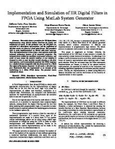
where the parameter λ, referred to as warping coefficient may vary between –1 and 1. This transformation is the basis of the frequency warping technique. It results in a re-mapping of the complex plane, so that the z frequency plane is changed into a new ζ complex plane. This bilinear transformation is graphically represented in fig. 1 as a function of λ.
Figure 1 - Bilinear transformation of frequency with different λ values The application of this transformation to the spectrum of an audio signal results in a stretching of the signal spectrum so that it becomes approximately logarithmic and thus more consistent with a psychoacoustics frequency scale, like the Bark scale. The main advantage is that the transformed signal is more consistent with the human hearing capability. Therefore the warped filters have higher accuracy at low frequencies, where the human ear feature a high sensitivity, and lower accuracy at high frequencies. The choice of λ allows tuning the warping level, and from an acoustic point of view, it allows an approximation of the Bark scale [5]. The best value of λ depends on the sampling frequency, and Smith [6] provides to this aim an analytical expression. For instance when the sampling frequency fs is 44.1 kHz λ is around 0.8. Advantages and drawbacks of warped filters are addressed by its specific differences versus “classical“ filters. In a classical filter the frequency resolution is constant in all the frequency range, fig. 2. Since human hearing sensitivity is so that frequency resolution is of about one third of octave the equalization is unnecessarily fine at high frequency and too poor at low frequencies. Therefore very long FIR filters are required to obtain good results in the whole frequency range. A warped filter on the Bark scale allows a better resolution and a more effective equalization at low frequencies. Specifically a warped FIR filter can be implemented with a number of taps ten times lower than those of a FIR filter, still featuring the same low-frequency equalization.
As an example fig. 2 shows the magnitude of the frequency response of the equalization filter to be implemented inside a car, on a linear frequency axis. Fig. 3 shows the same response pre-warped with a negative value of the warping coefficient: the spectrum was stretched, increasing the bandwidth of the low-frequency part and compressing the high frequency. Common algorithms for the synthesis of FIR coefficients can be adopted to approximate this distorted spectrum. If such coefficients are used with a WFIR structure, setting a suitable positive value of the warping coefficient λ, the frequency response shown in fig. 4 is obtained. This last chart clearly states the increase of resolution in the low part of the frequency spectrum.
Figure 4 - Frequency response of the WFIR. The implementation of a Warped FIR structure is possible with the flow diagram shown in fig. 5 [7]. In principle, this structure is similar to the traditional FIR, where unit delays are replaced by the all-pass operators D1(z):
D1 ( z ) =
z −1 − λ
1 − λ ⋅ z −1
(2)
Figure 2 - Frequency response – original (FIR).
Figure 3 - Pre-warped frequency response Figure 5 - WFIR theoretical general structure. Unfortunately the above structure is not suitable for simple implementations in DSP units working on discrete-time processing. Thus an equivalent explicit structure was developed, as shown in fig. 6,
which allows for efficient implementation on common architectures [7].
where α is the pole value. The inverse transformation produces a time-domain series whose expression is
:n = 0 0 f (n ) = n −1 :n > 0 α
Figure 6 - practical structure of the WFIR Due to the introduction of the D1(z) all-pass block the warping produces a distortion of the complex plane. From the analysis of the warped z-plane it results that the points on the unitary circle are kept on it, the point inside are kept inside, and the point outside are kept outside. Therefore an unstable system cannot become stable, while a stable system keeps its propriety. This means that a warped FIR filter is always stable, even it is no more a “finite response” filter, as the network shown in fig. 6 contains loops. However, after the warping operation all the poles and zeroes but the DC component and Nyquist frequency (z=1 and z=-1 respectively) of the system are re-mapped in agreement to D1(z). It can be shown that for the points near to +1 the distance from the unitary circle increases, whilst it decreases for the points near -1. It stems from these considerations that the timedomain behavior of a warped signal is remarkably changed. A proof of this can be inferred, considering the impulse response of a simple system, whose z-transformation features only a pole in the real axis. Its expression on the z-domain is
F(z) =
1 z−α
(3)
(4)
The time constant τ is defined as the time necessary to reduce the system output to the 36.7% of the maximum value, i.e. to the 1/e percentage of the maximum. As an example, considering an impulse response described by f(n) the time constant can be computed from the expression of f(n) and its value is expressed in samples. (5) n = 1 + log α (1 / e) Therefore a time constant equal to about 100 samples is associated to a system with a single, low frequency pole at 0.99. If the system is warped with λ=0.8, the above mentioned pole (0.99) is remapped in 0.9135; instead, a system with an high frequency pole near Nyquist frequency, e.g. -0.99, would be re-mapped in -0.9989. This means that the time constant for the low frequency pole is just 12, whilst it is 900 samples for the high frequency pole. When warping is applied to an impulse response, the low frequency information is compressed in the first samples of the impulse response, while the high frequency components are stretched toward the last samples. In summary, a warped impulse response can be truncated after a few samples, without losing low frequencies information. This propriety holds especially for high values of λ. In the time domain the transformation of the frequency domain produces a compression of the information related to the low frequency part of the spectrum in the first samples. This is shown in the following through some experimental results. Fig. 7 reports the impulse response of a car-audio loudspeaker measured in an anechoic chamber. It also represents the taps of the FIR filter, which can approximate the loudspeaker behavior. If we abruptly truncate this sequence, for instance keeping only the first 30 samples, the amplitude of the system frequency response is strongly distorted, as graphically reported in fig. 8.
Figure 9 Warped Loudspeaker impulse response Figure 7 Loudspeaker impulse response, measured in an anechoic chamber.
Figure 8 Amplitude of the loudspeaker frequency response before (solid line) and after the truncation (dashed line). Fig. 9 on other side shows the impulse response obtained with the WFIR structure, with λ = 0.8. As expected from the theory, some sort of compression arises. Information is packed in the first samples, although the whole length is increased.
In fact, if the same abrupt truncation after 30 samples is applied to the warped signal, the spectrum is kept almost unchanged especially in the low frequency part, as shown in fig. 10. The high frequency part, on the other side, is completely different from the original one.
Figure 10 Amplitude of the warped loudspeaker frequency response before (solid line) and after the truncation (dashed line). Thus, given a limited number of available taps, warped FIR filters are more accurate at low frequency and coarser at high frequency in comparison with a FIR filter having the same number of taps.
2 Stereo-Dipole inverse filters computation The approach employed here is derived from the formulation originally developed by Kirkeby and Nelson [4,8]. Fig. 11 shows the cross-talk phenomenon in the reproduction space:
domain, where the convolutions are simply multiplications, with the following formula:
convolver
C(ω) = FT(h ll ) ⋅ FT(h rr ) − FT(h lr ) ⋅ FT(h rl ) (7)
fll flr
xl Binaural stereo signal
frl yl frr
xr
Then, the complex inverse of it is taken, adding a small, frequency-dependent regularization parameter:
yr
InvDen(ω) =
yr
yl
R
L hlr
hrl
hll
hrr pl
pr
Conj[C(ω)] Conj[C(ω)]⋅ C(ω) + ε(ω)
(8)
The function ε(ω) is set to a constant, small value in the useful frequency range of the loudspeakers employed for reproduction (80 – 16k Hz in this case), and a much larger value outside the useful range. A smooth, logarithmic transition between the two values is interpolated over a transition band of 1/3 octave. Fig. 12 shows the graphical user interface of the software developed for computing the cross-talk canceling filters:
Fig. 11 – cross-talk cancelling scheme The 4 cross-talk cancelling filters fij, which are convolved with the original binaural material, must be designed in order to match the signals received at the ears of the listener with the original ones. Forcing the following constraints: pl=xl and pr=xr, a 4x4 linear equation system is obtained. Its solution yields:
f ll = (h rr ) ⊗ InvDen f = (− h ) ⊗ InvDen lr lr ( (6) f h rl = − rl ) ⊗ InvDen f = (h ) ⊗ InvDen ll rr InvDen = InvFilter(h ll ⊗ h rr − h lr ⊗ h rl )
The critical problem is the computation of the InvFilter (denominator), as its argument is generally a mixed-phase function. In the past, the authors attempted [9] to perform such an inversion employing the approximate methods suggested by Neely&Allen [10] and Mourjopoulos [11], but now the Kirkeby-Nelson frequency-domain regularization method is preferentially employed, due to its speed and robustness. A further adaptation over the previously published work [12] consists in the adoption of a frequency-dependent regularization parameter. In practice, the denominator is directly computed in the frequency
Fig. 12 – Graphical user interface of the inverse filter module This software tool was implemented as a CoolEdit plug-in, and it can process directly a stereo impulse response (assuming a symmetrical setup, so that hll=hrr and hlr=hrl), or a complete 2x2 impulse responses set, obtained placing first the binaural IR coming from the left loudspeaker, followed in time by the binaural IR coming from the right loudspeaker. In both cases, the computed inverse filters are in the same format as the input IRs. The computation is so fast (less than 100 ms) that it is easy to find the optimal values for the regularization parameters by an error-and-trial method.
This inversion procedure for equalization was adopted for both FIR and WFIR synthesis. The only difference is that for WFIR synthesis the measured impulse responses are pre-warped before computing the inverse filter coefficients, employing another CoolEdit plugin, described in the next chapter.
3. Implementation of the WFIR structure as an audio plugin and as DSP code The WFIR structure illustrated in fig. 6 was first translated in an equivalent C-language code, suitable to operate on discrete-time samples of a sound waveform. The algorithm can be implemented with a single cycle, which is repeated as many times as the number of coefficients of the WFIR. The body of the cycle requires 3 multiplications and 3 sums, plus 4 memory operations (3 retrieves and one store). Moreover the algorithm requires a memory space as long as the number of filter coefficients, in order to store the partial sums of each stage. In comparison, the traditional FIR algorithm is much cheaper, as the body of its main cycle requires only a single multiplication and addition, and two memory operation (retrieving the coefficient and the sample). The related computational cost thus is approximately given by the ratio 10/4, provided that we assign the same weight to multiplication, addition and memory operations. Then the C code was embedded in a CoolEdit plugin, which was very useful in order to mimic the behavior of the DSP code (allowing for listening tests, although not in real-time) and to pre-warp the measured impulse responses. This allows the design of WFIR filters as well as the standard operations on discrete-time waveforms, already developed under CoolEdit environment [9]. Fig. 13 shows the user’s interface of the “ConvoWarp” module.
Fig. 13 – user’s interface of the WFIR module
From the user point of view his module simply requires that the WFIR coefficients are loaded onto the clipboard (in WAV format), then allows for processing of stereo audio signal with up to 4 separate WFIR filters, and thus is ideal for crosstalk canceling networks. When the plugin is employed for the pre-warping of measured impulse response coefficients, a negative value of λ must be used. Furthermore, a Dirac’s delta function (1 followed by thousands of zeroes) is fed into the warped filter structure using the measured impulse response as coefficients of the WFIR. This operation produces the set of prewarped coefficients. The next step was the translation of the C code into assembly. Both WFIR and FIR architectures were implemented on an evaluation board equipped with an AD 21065L SHARC processor in assembly code for efficiency purposes. This DSP unit is capable of real-time processing up to approximately 900 multiply-add operations at a sampling rate of 48 kHz. This means that with the traditional FIR implementation approximately 225 taps for each of the 4 cross-talk canceling filters are allowed at maximum. Exploiting the parallel processing capabilities of the SHARC processor, the WFIR code was implemented with only 5 lines of code in the inner cycle, and thus in this case the computational cost of the WFIR is exactly 5 times of that of a traditional FIR. Thus, the maximum number of taps for each WFIR cross-talk canceller is 45. The DSP program is controlled by the IRQ1 and IRQ2 switches, which were set up to toggle between the two algorithms, giving visual feedback through the status LEDs. So doing it is possible to switch instantaneously between FIR and WFIR processing, without noticeable abruption of the signal.
4. Experimental results Experiments and listening tests were performed at ASK Industry, Italy, inside a treated listening room, equipped with a pair of professional-grade selfpowered monitor loudspeakers (Dynaudio). The loudspeakers were arranged in the stereo dipole configuration (relative distance between the acoustic center was 350 mm, and the listener’s head was 2m apart). First, the binaural impulse responses were measured, making use of a Bruel&Kjaer head and torso simulator type 4100, of a PC equipped with a professional sound board (Echo Layla) and
of the Aurora measuring software [9]. Fig. 14 shows the situation during the measurements.
Figure 14 – ASK listening room measurement Fig. 15 shows the measured impulse responses of the system, corresponding to the 4 impulse responses referred to as f in fig. 8. First, a set of very long inverse FIRs was computed (2048 taps each), as shown in fig. 16. When these filters are employed (running them with the Aurora convolution plugin under CoolEdit), a good equalization and cross-talk cancellation is obtained, as shown in fig. 17.
Fig. 16 – long cross-talk cancelling filters
Fig. 17 – cross-talk cancellation with long FIR Fig. 15 – Measured Binaural Impulse Responses and corresponding frequency response
Despite the length of these inverse filters, the equalization is good only above 600 Hz: at lower frequency the response is quite uneven, although the cancellation of the cross-talk remains very effective. After this, the “short” FIR and WFIR inverse filters were derived, respectively 220 and 42 taps long. Fig. 18 and 19 show the short FIR inverse filters and their effect when applied to the system of fig. 15, respectively. Similarly, fig. 20 and 21 show the WFIR coefficients, and the filtering effect of the WFIR structure. From these results, it is clear that the short FIR only behaves correctly at medium/high frequency, providing an overall response badly equalized, with great problems at low frequency. On the other hand, the WFIR gives an overall flat spectrum starting from much lower frequencies, although the crosstalk cancellation is somewhat less effective, and the time response is slightly “smeared”.
Fig. 19 – cross-talk cancellation with short FIR
Fig. 18 – short FIR filters
Fig. 20 – WFIR coefficients
(the 5% critical F-value was 4.2252, which means that values greater than it indicate that the difference between A and B is significant). Question
Avg. A Avg. B Anova's F factor Overall appreciation 3.57 4.79 34.47 Image localization 3.79 4.36 4.38 Stage amplitude 3.50 4.71 21.72 Naturality 3.71 4.57 10.88 Low frequency resp. 3.29 4.36 11.56 Mid frequency resp. 3.79 4.07 1.60 Hi frequency resp. 4.14 4.43 0.98
5. Subjective comparison The audible performances of the two digital filtering techniques were compared in a blind subjective test. 14 normal-hearing subjects were employed, aged between 20 and 36, 6 were females. The subjects were not trained to auditorial tests, nor they knew anything about the research and the goals of the experiment. Each subject was comfortably seated at the “sweet spot“ in front of the Stereo-Dipole loudspeaker pair. He was given control on the DSP unit through the two selection buttons and LEDs, which were labeled A and B. The subject was not aware of the fact that A was FIR and B WFIR. A CD player was generating the test signals (binaural recording of natural sounds on the beach, and of music inside a car compartment). The listener was free to switch in any moment between A and B filters. He had to compile a questionnaire containing 7 attributes, rating each of them on a 5-steps verbal scale (insufficient, mediocre, sufficient, fair, good). A separate evaluation was given for each question to systems A and B. The results were analyzed with a classical ANOVA (performed thanks to the Excel analysis toolpack). The following table presents the statistical results
0.00% 4.63% 0.01% 0.28% 0.22% 21.71% 33.10%
Also the probability that A and B responses are the same was computed; the ANOVA’s results can be seen in graphical form in fig. 19. From the table above and from fig. 22, it is clear that system B (WFIR) was significantly better than system A in questions 1, 3, 4 and 5. The significance is at limit for question 2 (prob. 4.63%), and there is no substantial difference in question 6 and 7. This means that the WFIR is globally better, and particularly because it widens the stereo image, it is more natural, and has deeper low-frequency response. Some subjects reported also that system A is more dry, whilst system B is softer (and this is certainly due to the time smearing already shown in the previous chapter). Averages, standard deviations and ANOVA probability results 6
5.5
0.00%
4.63%
0.01%
0.28%
1-Overall appreciation
2-Image localization
3-Stage amplitude
4-Naturality
0.22%
21.71%
33.10%
5
4.5 Score
Fig. 21 – cross-talk cancellation with WFIR
Prob.
4
3.5
3
2.5
2
5-Low frequency 6-Mid frequency 7-High resp. resp. frequency resp.
Question A - FIR
B - WFIR
Fig. 22 – Anova of the subjective responses
Conclusions In this paper a novel digital equalizing system for car audio systems was presented and validated with several listening tests and experiments. The digital filtering is based on a multichannel warped FIR structure, and it was implemented on a low cost DSP-based board. An automatic procedure for the
synthesis of the filter coefficients was developed, starting from standard acoustic measurements, in the form of plugins developed for the shareware program CoolEdit. Adopting the WFIR filter structure the flattening of the amplitude of the frequency response is nice, and from the subjective point of view the sharpness and quality of the reproduction is pretty increased and the frequency response in the low frequency range is more natural. From the spatial point of view, although the WFIR produces less cross-talk cancellation than the FIR structure with the same computational cost, it resulted that the perceived stereo image is wider and more enveloping.
Acknowledgements This work was sponsored by ASK Automotive Industries, Reggio Emilia, Italy, under a research contract co-funded by MURST (Italian Ministry for University and Research) and by EC under the ESPRIT project APLODSP 28.583. Substantial support also came from The Ambiophonic Institute (www.ambiophonic.org), where the warped stereo dipole filters got their first, encouraging listening tests. Some helpful hints regarding the code development on the 21065L platform were given by Gianfranco Cibelli and Filippo Bruschi (from ASK). Analog Devices is acknowledged for supplying free hardware and software in support of this research.
References [1] W. Klippel, “Compensation for Nonlinear Distortion of Horn Loudspeakers by Digital Signal Processing”, Journal of the Audio Engineering Society, November 1996, vol. 44, n. 11, pp 964-972 [2] A. Bellini, G. Cibelli, E. Ugolotti, A. Farina and C. Morandi, “Non-linear Digital Audio Processor for dedicated loudspeaker systems”, IEEE Trans. on Consumer Electronics, August 1998, pp. 1024-1031 [3] G. Cibelli, A. Bellini, E. Ugolotti, A. Farina, C. Morandi, “Experimental validation of loudspeaker equalization inside car cockpits”, preprint #4898 of AES 106th convention, Munich, Germany, May 1999 [4] O. Kirkeby, P. A. Nelson, H. Hamada – “The "Stereo Dipole"-A Virtual Source Imaging System Using Two Closely Spaced Loudspeakers” – JAES vol. 46, n. 5, 1998 May, pp. 387-395.
[5] E. Zwicker and H. Fastl, “PsychoacousticsFacts and Models”, Springer, Berlin, 1990 [6] J. O. Smith and J. Abel, “The Bark Bilinear Transform”, in Proc. of IEEE ASSP Workshop, 1995, Mohonk, New Platz, NY [7] M. Karjalainen and E. Piirilä and A. Järvinen, “Loudspeaker Response Equalisation Using Warped Digital Filters”, Proc. of NorSig-96, September 1996, Espoo, Finland, pp. 367-370 [8] O.Kirkeby, P.A. Nelson, P. Rubak, A. Farina "Design of Cross-talk Cancellation Networks by using Fast Deconvolution" - 106th AES Convention, Munich, 8-11 may 1999. [9] A. Farina, F. Righini, ‘Software implementation of an MLS analyzer, with tools for convolution, auralization and inverse filtering’, Pre-prints of the 103rd AES Convention, New York, 26-29 September 1997. [10] S.T. Neely, J.B. Allen, ‘Invertibility of a room impulse response’, J.A.S.A., vol.66, pp.165-169 (1979). [11] J.N. Mourjopoulos, “Digital Equalization of Room Acoustics”, JAES vol. 42, n. 11, 1994 November, pp. 884-900. [12] A. Farina, E. Ugolotti - "Spatial Equalization of sound systems in cars" - Proc. of 15th AES Conference "Audio, Acoustics & Small Spaces", Copenhagen, Denmark, 31/10-2/11 1998.