IOP PUBLISHING
JOURNAL OF MICROMECHANICS AND MICROENGINEERING
doi:10.1088/0960-1317/18/2/025018
J. Micromech. Microeng. 18 (2008) 025018 (6pp)
Implementation of silicon-on-glass MEMS devices with embedded through-wafer silicon vias using the glass reflow process for wafer-level packaging and 3D chip integration Chiung-Wen Lin1, Chia-Pao Hsu2, Hsueh-An Yang3, Wei Chung Wang1,3 and Weileun Fang1,2 1
Institute of NanoEngineering and MicroSystems, National Tsing Hua University, Hsinchu, Taiwan Department of Power Mechanical Engineering, National Tsing Hua University, Hsinchu, Taiwan 3 Advanced Semiconductor Engineering Inc., Kaohsiung, Taiwan 2
E-mail:
[email protected]
Received 23 October 2007, in final form 30 November 2007 Published 4 January 2008 Online at stacks.iop.org/JMM/18/025018 Abstract This study presents a novel system architecture to implement silicon-on-glass (SOG) MEMS devices on Si–glass compound substrate with embedded silicon vias. Thus, the 3D integration of MEMS devices can be accomplished by means of through-wafer silicon vias. The silicon vias connecting to the pads of devices are embedded inside the Pyrex glass. Parasitic capacitance for both vias and microstructures is decreased and mismatch of coefficient of thermal expansion (CTE) is reduced. In applications, the glass reflow process together with the SOG micromachining processes were employed to implement the presented concept. Successful driving of the resonator through the silicon vias is demonstrated. The wafer-level hermetic packaging can be further achieved by anodic bonding of a Pyrex7740 wafer. Hermeticity of the packaged device performed by helium leak test satisfied MIL-STD-883E. The packaged SOG device is SMT (surface mount technology) compatible and ready for 3D microsystem integration. (Some figures in this article are in colour only in the electronic version)
of MEMS devices can be accomplished by means of throughwafer interconnections. For instance, approaches to fabricate through-wafer vias in a capping wafer have been reported [6, 7]. Through-wafer vias embedded inside the substrate of MEMS devices are employed in [8–11]. Metal deposition and electroplating are the most popular approaches to prepare the interconnections inside throughwafer vias [6–8]. However, the aspect ratio of the metalvia is limited to the deposition process. For instance, voids may occur in high aspect ratio metal electroplating, and the conformal coating of high aspect ratio vias is a challenge for physical vapor deposition of metal. Moreover, failure may arise from the large coefficient of thermal expansion (CTE)
1. Introduction The 3D integration of chip sets is regarded as a promising device architecture for next generation microsystems. The chip size of integrated circuits (IC) can be significantly reduced after replacing planar 2D interconnects with vertical 3D interconnects. Presently, various research on 3D heterogeneous integration of IC has been reported, for instance the vertical stacking of chips with [1–3] or without interposer [4, 5]. Similarly, the 3D MEMS packaging also provides many advantages such as smaller footprint and SMT compatibility. Thus the techniques to realize 3D integration of MEMS devices attract considerable attention. In general, the 3D integration 0960-1317/08/025018+06$30.00
1
© 2008 IOP Publishing Ltd
Printed in the UK
J. Micromech. Microeng. 18 (2008) 025018
C-W Lin et al
mismatch between the metal and silicon. On the other hand, for non-RF MEMS applications [9–11], single crystal silicon (SCS) is also employed to act as the through-wafer vias. These SCS vias are directly patterned on the low-resistivity silicon substrate by BOSCH DRIE (deep reactive ion etching) technology. Hence, high-aspect-ratio vias and small via pitch can be achieved. The electrical insulation of these SCS vias is easily provided by air [9] and dielectric materials [10, 11] during the fabrication processes. The glass flow process (GFP) technology has been exploited in [12] to mold the glass using the silicon substrate. The GFP technology is further employed to massively fill the dielectric material into a silicon substrate with SCS vias [13]; thus, a glass capping with SCS vias is achieved. According to the simple fabrication process, the applications of silicon-on-glass (SOG) wafers for MEMS devices are gradually increased. The SOG wafer is prepared after the bonding of single crystal silicon with Pyrex 7740 glass (chemical composition: SiO2 80.6%, Na2O 4.0%, B2O3 13.0%, Al2O3 2.3% and miscellaneous traces 0.1% [14]). The typical SOG MEMS processes involve the patterning of silicon device layer using BOSCH DRIE, and the following microstructure releasing process using HF glass etching. Since the SOG wafer employs the dielectric glass as the handling substrate, the parasitic capacitance noise can be significantly reduced. This characteristic is especially attractive for capacitance-type MEMS sensors [15–17]. This study presents a glass reflow process to implement SOG MEMS devices on Si–glass compound substrate with embedded silicon vias, as shown in figure 1(a). The silicon vias are patterned by photolithography and DRIE, and then hermetically sealed by Pyrex7740 after the glass reflow process. Meanwhile, the single crystal silicon (SCS) on Si–glass compound substrate is exploited to fabricate MEMS devices. This SOG device with embedded silicon vias is ready for 3D integration with IC, as shown in figure 1(b). The merits of this device architecture and process flow are: (1) parasitic capacitance for both vias and microstructures is decreased; (2) mismatch of coefficient of thermal expansion (CTE) is reduced; (3) ease of wafer-level 3D integration of MEMS devices; (4) ready for wafer-level hermetic packaging by anodic bonding and (5) compatible with surface mount technology (SMT).
SOG devices (a)
Reflow glass (b)
Silicon via
Hermetic
Sensing/driving IC
Figure 1. The concept of the present system architecture, (a) the SOG devices with embedded through-wafer silicon via and (b) the packaging and 3D integration of the present SOG device. (a)
(e)
(b) (f)
(c)
(g)
(h) (d)
2. Concept and process steps
Sensing/driving IC
Silicon
The fabrication process illustrated in figure 2 has been established to implement the present architecture in figure 1(a). As shown in figure 2(a), the photolithography and the BOSCH DRIE were performed on the backside of doubleside polished silicon wafer to fabricate the cavities and silicon vias. The planar dimensions of via and the pitch between vias were defined by photolithography. The length of via and the thickness of SOG device were determined by DRIE. As shown in figure 2(b), anodic bonding of Pyrex7740 glass wafer and silicon wafer was performed using a commercial bonder in vacuum chamber, with voltage of 1000 V and temperature of 400 ◦ C. In general, the ambient pressure in the vacuum chamber was 5 mTorr during bonding, and the pressure inside
Glass
Metal
Solder
Figure 2. Process flow for SOG devices with embedded through-wafer SCS vias.
the cavity sealed by silicon and glass was much smaller than 1 atm after bonding. As illustrated in figure 2(c), the bonded Si–glass wafer was then placed into a 750 ◦ C furnace for 6 h to perform the glass reflow process. Under the assistance of pressure load, the spaces surrounding silicon vias were filled with glass. As shown in figure 2(d), the lapping process was used to planarize the surface of reflow glass. Moreover, this process was also employed to expose one end of the silicon vias for electrical interconnection. Thus, Si–glass 2
J. Micromech. Microeng. 18 (2008) 025018
C-W Lin et al
compound substrate with embedded through wafer silicon vias was achieved. As shown in figure 2(e), the SCS on Si–glass compound substrate was patterned by photolithography and DRIE to define the microstructures. The compound substrate was then immersed into HF solution to isotropically etch the glass. The backside of the compound substrate was protected using a chuck with O-ring sealing during the HF etching. The microstructures were fully released after glass etching, so as to form the suspended SOG devices with embedded silicon vias, as shown in figure 2( f ). The wafer-level packaging of MEMS devices can be further accomplished after capping with Pyrex7740 glass wafer. Thus, as illustrated in figure 2(g), the electrical interconnect was easily achieved using the silicon vias. Moreover, an additional patterned metal layer at the backside of the compound substrate was exploited to redistribute the bonding pads. The wafer-level 3D integration of MEMS devices and other chips is also achieved, as shown in figure 2(h).
(a)
5mm
(b)
3. Experiment and results 453.8µm
To demonstrate the feasibility of the present concept shown in figure 2, various SOG devices with embedded through-wafer silicon vias were fabricated on Si–glass compound substrate. The following wafer-level capping of these SOG devices using Pyrex7740 glass wafer is also implemented. In addition, various tests regarding the performances of silicon vias and SOG devices, and the quality of 3D packaging unit were also investigated.
84.77µm
Figure 3. (a) The optical micrograph and (b) the measured surface profile of substrate right after the glass reflow process shown in figure 2(c).
3.1. Fabrication and integration After the glass reflow process, the optical image of this Si– glass compound substrate is shown in figure 3(a). The glass massively filled into the silicon cavity after the reflow process is clearly observed. As shown in figure 3(b), the profile measured using a stylus profilometer indicates the surface topology of Pyrex7740 glass after the reflow process depicted in figure 2(c). The maximum depth variation of the glass surface is 453.8 µm which is very close to the via-depth of 450 µm defined by DRIE. It indicates that the reflow glass has properly filled into the cavity surrounding the via. The photo in figure 4(a) shows the planarized Si–glass compound substrate with embedded silicon vias after glass lapping (as illustrated in figure 2(d)). It is also observed from the zoom-in photo in figure 4(a) that one end of the silicon vias is exposed successfully, whereas, the vias remain surrounded by the glass. Moreover, this study further placed the sample into HF solution for 7 min to remove 53 µm thick glass from the backside of the compound substrate, as shown in figure 4(b). Thus, part of the SCS via is exposed from the glass, and the rest of this SCS via (approximately 397 µm long) is still embedded inside the glass. As shown in the zoom of the SEM micrograph in figure 4(b), the glass is in tight contact along the periphery of SCS via. The SEM micrograph in figure 5 shows a patterned SCS microstructure on Si–glass compound substrate (as the process shown in figure 2(e)). The silicon and the glass on this compound substrate are indicated in the photo. In addition,
Exposed silicon via (a)
5mm
Surrounding glass (b)
Silicon
Figure 4. (a) The optical micrographs of SCS vias and surrounding Si–glass compound substrate after the lapping process in figure 2(d) and (b) the SEM micrographs of the SCS via and its surrounding glass after removing 53 µm thick glass by HF. 3
J. Micromech. Microeng. 18 (2008) 025018
C-W Lin et al
(a)
Silicon Refilled glass
(b) 4mm
Figure 5. The SEM micrograph of a patterned SCS microstructure on Si–glass compound substrate.
this photo also clearly shows that the cavity underneath the patterned SCS structures is completely filled by the reflow glass. Figure 6(a) shows SEM micrographs of two typical fabricated devices, including a linear accelerometer (left) and a comb-drive resonator (right). The glass underneath the suspended microstructures has been fully removed by isotropic etching indicated in figure 2( f ), so as to lead to a rough surface. As shown in figure 6(b), the broken substrate is further employed to show the silicon via under the bonding pad and the fully suspended SCS structure. The silicon vias are connecting perfectly with the bonding pad. In addition, the silicon vias are anchored to the Si–glass substrate properly by the surrounded glass. The chips in figure 7(a) show various packaged
Figure 7. The optical micrographs of (a) various packaged SOG devices and (b) the transparent region of the packaged device shows the existence of glass on the compound substrate.
SOG MEMS devices on the present Si–glass compound substrate using the wafer-level packaging process indicated in figure 2(g). Thus, various typical SOG MEMS devices such as accelerometers and gyroscopes with embedded SCS vias can
(a)
(b)
Glass
Glass
Silicon via
Silicon via
Silicon via Glass
Figure 6. The SEM micrographs of (a) two typical fabricated SOG devices after being suspended from the substrate and (b) the cross-sectional view of the SOG device which clearly shows the suspended SCS microstructures and SCS vias. 4
J. Micromech. Microeng. 18 (2008) 025018
Stroboscope
C-W Lin et al
Spectrum Analyzer
2.5
Amplitude (µm)
2.0 1.5 1.0 0.5 0.0 800
900
1000
1100
1200
1300
1400
1500
Frequency (Hz)
AC power supply
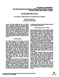
Figure 9. The typical measured frequency response of the SOG resonator.
was less than 5 min. After that, the test sample was placed into a vacuum chamber to measure the leakage of He gas. The measured helium leak rate was 5.0 × 10⁻⁸ atm cc s−1. This result indicates that the present SOG MEMS device with embedded SCS vias has satisfied the test standard of MILSTD-883E, method 1014.9 [18]. 25mm
4. Conclusions Figure 8. The experimental setup to measure the dynamic response of a SOG resonator.
This research successfully demonstrates a novel device architecture for SOG MEMS components on Si–glass compound substrate with embedded SCS vias. The GFP process was used to prepare the Si–glass compound substrate. The SCS vias monolithically integrated with the pads of MEMS devices are embedded inside the bulk Pyrex glass. Parasitic capacitance for both vias and microstructures is decreased and mismatch of CTE is reduced. In applications, the GFP together with SOG micromachining processes were performed to implement the presented device architecture. Successful driving of a resonator through the vertical silicon vias has been demonstrated. Moreover, wafer-level packaging was also accomplished by capping the present device with Pyrex7740 glass wafer. The measurements showed that the packaged device with embedded silicon vias had a helium leak rate of 5 × 10⁻⁸ atm cc s−1, which satisfied the standard of MIL-STD-883E. The leakage can be further reduced by adjusting the glass reflow parameters such as temperature ramping–cooling procedure. This SOG device with embedded through-wafer silicon vias is a promising approach for the heterogeneous integration of driving and sensing circuits by vertical stacking. As a result, the final packaged SOG device is SMT compatible and ready for 3D integration. The present process has the potential to provide design flexibility and fabrication advantages. For instance, as shown in figures 2(b)–(c), a thin silicon device layer may experience the risks of deformation or damage during the thinning and bonding processes. In this regard, a thick silicon device layer can be employed in the processes of figures 2(a)–(c). After that, an additional chemical mechanical polishing (CMP) process can be applied in figure 2(d) for the thinning of the silicon device layer. In addition, the pressure inside the cavity
be packaged using this technique. The transparent regions in figure 7(b) show the existing glass on the compound substrate. 3.2. Tests The test setup in figure 8 was established to measure the dynamic response of the micromachined SOG actuators, so as to further characterize the performance of embedded throughwafer silicon vias. The chip containing the SOG resonator was bonded on a PCB, and the driving signal from an AC power supply was provided to the resonator through the SCS via, as depicted in figure 8. The in-plane dynamic response of the resonator was measured using a commercial stroboscope with a resolution of 0.1 µm. Figure 9 shows the typical dynamic response of the resonator driven at the frequency range of 800– 1400 Hz, and the measured resonant frequency is 1.10 kHz with a quality factor of 40.89. As a result, the test demonstrates that the present process successfully fabricates SOG MEMS devices on Si–glass compound substrate. Moreover, the packaged device has been successfully driven through the present SCS vias. Following the conditions specified in MIL-STD-883E, method 1014.9, the hermeticity of the SOG MEMS device with embedded SCS vias was evaluated by an industrial helium leak test system. As shown in figure 2(g), the test sample had an equivalent packaging volume of 0.72 mm3. The sample was placed into a chamber with high ambient pressure of He gas to force the He into the space sealed by the sample. The bomb pressure was 5 bar for 2 h. The dwell time of this test 5
J. Micromech. Microeng. 18 (2008) 025018
C-W Lin et al
sealed by silicon and glass in figure 2(b) can be increased during the bonding process. This will lead to an air gap between the interface of the device silicon layer and the reflow glass in figure 2(c). Thus, the higher lateral etching rate at the interface of silicon and glass during DRIE (named the notching effect) [19] can be prevented.
[5] Benkart P, Kaiser A, Munding A, Bschorr M, Pfleiderer H-J, Kohn E, Heittmann A, Huebner H and Ramacher U 2005 3D chip stack technology using through-chip interconnects Design Test Comput IEEE 22 512–8 [6] Kaajakari V, Kiihamaki J, Oja A, Seppa H, Pietikainen S, Kokkala V and Kuisma H 2005 Stability of wafer level vacuum encapsulated single-crystal silicon resonators Transducers’05 (Seoul, Korea, 5–9 June) pp 916–9 [7] Receveur R A M, Zickar M, Marxer C, Larik V and de Rooij N F 2006 Wafer level hermetic package and device testing of a SOI-MEMS switch for biomedical applications J. Micromech. Microeng. 16 676–83 [8] Lin C-W, Yang H-A, Wang W C and Fang W 2007 Implementation of three-dimensional SOI-MEMS wafer-level packaging using through-wafer interconnections J. Micromech. Microeng. 17 1200–5 [9] Lee S-H, Lee S W and Najafi K 2007 A generic environment-resistant packaging technology for MEMS Transducers’07 (Lyon, France, 10–14 June) pp 335–8 [10] Wei J, Vander Velden M and Sarro P M 2007 Fabrication of vertical electrodes on channel sidewall for picoliter liquid measurement Transducers’07 (Lyon, France, 10–14 June) pp 1612–6 [11] Bauer T 2007 High density through wafer via technology NSTI-Nanotech 2007 (Santa Clara, CA, USA, 20–24 May) pp 116–9 [12] Merz P, Quenzer H J, Bernt H, Wagner B and Zoberbier M 2003 A novel micromachining technology for structuring borosilicate glass substrates Transducers’03 (Boston, USA, 8–12 June) pp 258–61 [13] Fraunhofer ISIT, Itzehoe (DE) 2005 Electrical feedthroughs using wafer-level glass-flow technology Achievements and Results Annual Report 2005 http://www.isit. fraunhofer.de/german/download/JB2005A4.pdf [14] Description of glasses used in Corning Labware http://www. corning.com/Lifesciences/technical information/techDocs/ descglasslabware.asp#7740LowExpansion [15] Chae J, Kulah H and Najafi K 2005 A CMOS-compatible high aspect ratio silicon-on-glass in-plane micro-accelerometer J. Micromech. Microeng. 15 336–45 [16] Alper S E and Akin T 2005 A single-crystal silicon symmetrical and decoupled MEMS gyroscope on an insulating substrate J. Microelectromech. Syst. 14 707–17 [17] Lee M C, Kang S J, Jung K D, Choa S-H and Cho Y C 2005 A high yield rate MEMS gyroscope with a packaged SiOG process J. Micromech. Microeng. 15 2003–12 [18] MIL-STD-883E, US Department of Defense, 31 Dec. 1996 [19] McAuley S A, Ashraf H, Atabo L, Chambers A, Hall S, Hopkins J and Nicholls G 2001 Silicon micromachining using a high density plasma source J. Phys. D: Appl. Phys. 34 2769–73
Acknowledgments This project was (partially) supported by the NSC of Taiwan under grant NSC-95-2221-E-007-158 and the Ministry of Economic Affairs, Taiwan, under contract 95-EC-17-A-07S1-011. The authors would like to thank the NSC Central Regional MEMS Center (Taiwan), the Nano Facility Center of National Tsing Hua University, the Nano-Electro-MechanicalSystem Research Center of National Taiwan University and the NSC National Nano Device Laboratory (NDL) for providing the fabrication facilities. The author would also like to thank Advanced Semiconductor Engineering (ASE) Inc. Kaohsiung, Taiwan for the help in helium leak testing and Hsin-Hung Pan of Industrial Technology Research Institute (ITRI) of Taiwan for the help in the lapping process.
References [1] Stoukatch S, Winters C, Beyne E, De Raedt W and Van Hoof C 2006 3D-SIP integration for autonomous sensor nodes Proc. 56th Electronic Components and Technology Conf. (CA, USA, 30 May–2 June) pp 404–8 [2] VP G, Lim S, Witarsa D, Yin H W, Kumar M, Lim L A, Yoon S W and Kripesh V 2006 Assembly technology development for 3D silicon stacked module for handheld products Proc. 56th Electronic Components and Technology Conf. (CA, USA, 30 May–2 June) pp 1300–7 [3] Tanaka N and Yoshimura Y 2006 Low-cost through-hole electrode interconnection for 3D-SiP using room-temperature bonding Proc. 56th Electronic Components and Technology Conf. (CA, USA, 30 May– 2 June) pp 814–8 [4] Fukushima T, Yamada Y, Kikuchi H and Koyanagi M 2006 New three-dimensional integration technology using chip-to-wafer bonding to achieve ultimate super-chip integration Japan. J. Appl. Phys. 45 3030–5
6