Hindawi Publishing Corporation Mathematical Problems in Engineering Volume 2013, Article ID 249021, 8 pages http://dx.doi.org/10.1155/2013/249021
Research Article Improved Computing-Efficiency Least-Squares Algorithm with Application to All-Pass Filter Design Lo-Chyuan Su,1 Yue-Dar Jou,2 and Fu-Kun Chen3 1
Department of Computer and Information Science, R.O.C. Military Academy, Fengshan District, Kaohsiung 830, Taiwan Department of Electrical Engineering, R.O.C. Military Academy, P.O. Box 90602-6, Fengshan District, Kaohsiung 830, Taiwan 3 Department of Computer Science and Information Engineering, Southern Taiwan University of Science and Technology, Yongkang District, Tainan 710, Taiwan 2
Correspondence should be addressed to Yue-Dar Jou;
[email protected] Received 2 April 2013; Accepted 26 May 2013 Academic Editor: Ker-Wei Yu Copyright © 2013 Lo-Chyuan Su et al. This is an open access article distributed under the Creative Commons Attribution License, which permits unrestricted use, distribution, and reproduction in any medium, provided the original work is properly cited. All-pass filter design can be generally achieved by solving a system of linear equations. The associated matrices involved in the set of linear equations can be further formulated as a Toeplitz-plus-Hankel form such that a matrix inversion is avoided. Consequently, the optimal filter coefficients can be solved by using computationally efficient Levinson algorithms or Cholesky decomposition technique. In this paper, based on trigonometric identities and sampling the frequency band of interest uniformly, the authors proposed closed-form expressions to compute the elements of the Toeplitz-plus-Hankel matrix required in the least-squares design of IIR all-pass filters. Simulation results confirm that the proposed method achieves good performance as well as effectiveness.
1. Introduction Digital all-pass filters have received much attention in many signal processing applications such as notch filtering, phase equalization in communication systems, multichannel filter bank, construction of a wavelet, and image compression [1–9]. The most commonly used design methods can be classified into four categories: (1) maximally flat design [10], (2) least-squares approximation [11–15], (3) minimax approximation [16–18], and (4) cepstral coefficients method [19, 20]. The aforementioned approaches [11–18] include solving a set of linear equations, using a linear programming method, or utilizing a generalized exchange algorithm. Several different optimization methods have been developed based on efficiency or applications. No matter what methods are used, the computation increases significantly as the filter length increases. In the literature [13], an efficient and robust weighted least-squares (WLS) method is proposed to design IIR allpass filters that have a least-squares or an equiripple phase error response. The method is based on formulating a weighted square error reflecting the difference between the
desired phase and the phase response of the design IIR allpass filter in a quadratic form. The filter coefficients are then obtained by solving a system of linear equations which involves a Toeplitz-plus-Hankel matrix. Consequently, the optimal solution of this system of linear equations can be obtained efficiently using Cholesky decomposition or Levinson algorithm [21–23]. These efficient algorithms require only 𝑂(𝑁2 ) complexity [21–24] to compute the optimal solution. It is computationally efficient as compared to solving the linear equations by directly computing a matrix inversion which involves 𝑂(𝑁3 ) complexity. Furthermore, the computation of matrix inversion may cause numerical problems as the filter length is large. Therefore, the method proposed by Kidambi [13, 24] is not only efficient but also robust as applied to the filter design problems. It has been shown in [24] that the efficient algorithms do not result in numerical problem as the filter increases to 2000. As observed from the elements of Toeplitz-plus-Hankel matrix, they are associated with the filter specifications when the design problem is specified. Therefore, trigonometric properties can be further used to reduce the computation. In this paper, based on trigonometric identities and uniformly
2
Mathematical Problems in Engineering
sampling the band of interest, the elements of Toeplitzplus-Hankel matrix can be further simplified as closed-form expressions. Simulation results indicate that the computations can be greatly reduced as compared to the efficient algorithm presented by [13]. This paper is organized as follows. In Section 2, the problem formulation of IIR all-pass filter is briefly reviewed. In Section 3, the closed-form expressions for Toeplitz-plusHankel matrix are investigated in detail. The analysis of computational requirements is stated in Section 4. The simulation and design examples are shown in Section 5 to verify the advantages of the proposed method. Finally, the conclusion is stated in Section 6.
2. Problem Formulation The frequency response of an IIR all-pass filter with N real coefficients, ℎ(𝑛), 𝑛 = 0, . . . , 𝑁 − 1, can be expressed as 𝑗𝜔
𝐻 (𝑒 ) =
−𝑗𝜔𝑛 ∑𝑁 𝑛=0 ℎ (𝑁 − 𝑛) 𝑒 −𝑗𝜔𝑛 ∑𝑁 𝑛=0 ℎ (𝑛) 𝑒
=
𝑒−𝑗𝜔𝑁𝐷 (𝑒−𝑗𝜔 ) 𝐷 (𝑒𝑗𝜔 )
,
𝜃 (𝜔) = −𝑁𝜔 + 2 tan−1 (
1
𝑒 (𝜔) = 𝜃𝑑 (𝜔) − 𝜃 (𝜔)
where 𝜌𝑑 (𝜔) = (𝜃𝑑 (𝜔) + 𝑁𝜔)/2. After performing some mathematical treatment, (6) can be simplified as h𝑇 [sin [𝜌𝑑 (𝜔)] c (𝜔)−cos [𝜌𝑑 (𝜔)] s (𝜔)] ≈ − sin [𝜌𝑑 (𝜔)] . (7) As a consequence, (7) can be expressed in a more compact form h𝑇 s1 (𝜔) ≈ − sin [𝜌𝑑 (𝜔)] ,
(8)
where s1 (𝜔) = sin [𝜌𝑑 (𝜔)] c (𝜔) − cos [𝜌𝑑 (𝜔)] s (𝜔) , = [sin(𝜌𝑑 (𝜔)− 𝜔) sin (𝜌𝑑 (𝜔)−2𝜔) ⋅ ⋅ ⋅ sin (𝜌𝑑 (𝜔) − 𝑁𝜔)] .
(9)
Therefore, the objective function to be minimized in the leastsquares sense can be formulated in a quadratic form as 𝐿
2
𝐸 = ∑ {h𝑇 s1 (𝜔𝑙 ) + sin (𝜌𝑑 (𝜔𝑙 ))} ,
(10)
𝑙=1
∑𝑁 𝑛=1 ℎ (𝑛) sin (𝑛𝜔)
1 + ∑𝑁 𝑛=1 ℎ (𝑛) cos (𝑛𝜔)
). (3)
It is clear that the phase error response in (3) is a nonlinear representation of filter coefficients. Minimizing the phase error response directly will result in a highly nonlinear optimization problem. Based on the assumption of phase approximation presented by Kidambi [13], (2) can be alternatively rewritten as tan (
(6)
𝑇
(2)
Given a desired phase response, 𝜃𝑑 (𝜔), 0 ≤ 𝜔 ≤ 𝜋, the purpose is to find the real coefficients ℎ(𝑛) such that phase errors 𝑒(𝜔) can be minimized in the least-squares sense. The phase error response between 𝜃(𝜔) and 𝜃𝑑 (𝜔) can be represented as
= 𝜃𝑑 (𝜔) + 𝑁𝜔 − 2 tan−1 (
sin [𝜌𝑑 (𝜔)] h𝑇 s (𝜔) , ≈ cos [𝜌𝑑 (𝜔)] 1 + h𝑇 c (𝜔)
(1)
where the denominator is an FIR filter with frequency −𝑗𝜔𝑛 and ℎ(0) = 1. It can be response 𝐷(𝑒𝑗𝜔 ) = ∑𝑁 𝑛=0 ℎ(𝑛)𝑒 found that the magnitude response of 𝐻(𝑒𝑗𝜔 ) is unit gain at all frequencies. The phase response of 𝐻(𝑒𝑗𝜔 ) can be written as ∑𝑁 𝑛=1 ℎ (𝑛) sin (𝑛𝜔) ). + ∑𝑁 𝑛=1 ℎ (𝑛) cos (𝑛𝜔)
If the phase response of the design IIR all-pass filter is very close to the desired phase, that is, 𝜃𝑑 (𝜔) ≈ 𝜃(𝜔), then the expression in (4) can be approximated as [13]
𝑇
h s (𝜔) 𝜃 (𝜔) + 𝑁𝜔 )= , 2 1 + h𝑇 c (𝜔)
(4)
where h = [ℎ (1) , ℎ (2) , . . . , ℎ (𝑁)]𝑇 , c (𝜔) = [cos (𝜔) , cos (2𝜔) , . . . , cos (𝑁𝜔)]𝑇 , s (𝜔) = [sin (𝜔) , sin (2𝜔) , . . . , sin (𝑁𝜔)]𝑇 .
(5)
where 𝐿is the number of frequency points at which the desired phase is sampled. By setting 𝜕𝐸/𝜕ℎ(𝑖) = 0, for 𝑖 = 1, 2, . . . , 𝑁, a system of linear equations given by Qh = d is easily obtained, where 𝐿
Q = ∑ s1 (𝜔𝑙 ) ⋅ s𝑇1 (𝜔𝑙 ) , 𝑙=1
𝐿
(11)
d = − ∑ sin [𝜌𝑑 (𝜔𝑙 )] s1 (𝜔𝑙 ) . 𝑙=1
Since Q is a real, symmetric, and positive-definite matrix, a unique solution is guaranteed. In solving the system of linear equations, a matrix inversion Q−1 which involves 𝑂(𝑁3 ) complexity can be used directly. As the filter length is long, the computational complexity increases significantly. Furthermore, large filter length may cause the numerical
Mathematical Problems in Engineering
3
problem when the matrix is ill conditioned. Therefore, algorithms with efficient to design and robust to avoid numerical problem should be used.
3. Proposed Closed-Form Expressions for Toeplitz-Plus-Hankel Matrix
computational requirements for the associated matrices can be greatly reduced especially for filter length is large. Evidently, each element of matrix Q is the sum of cosine functions and can be written as a Toeplitz-plus-Hankel matrix form: 𝐿
Kidambi [13, 24] expanded the matrix Q into a sum of symmetric Toeplitz and Hankel matrix. Consequently, the system of linear equations can be written as (T + H) h = d. There exist several iterative and efficient algorithms [21– 23] which involve 𝑂(𝑁2 ) complexity that can be used to obtain the optimal filter. In this paper, some trigonometric identities [25] and uniformly sampled frequency points are exploited such that the Toeplitz and Hankel matrices can be further simplified as closed-form expressions. As a result, the 𝐿
𝑄 (𝑖, 𝑗) = ∑ sin [𝜌𝑑 (𝜔𝑙 ) − 𝑖𝜔𝑙 ] ⋅ sin [𝜌𝑑 (𝜔𝑙 ) − 𝑗𝜔𝑙 ] 𝑙=1
=
𝐿 1 𝐿 {∑ cos (𝑖−𝑗) 𝜔𝑙 − ∑ cos [(𝑖+𝑗) 𝜔𝑙 −2𝜌𝑑 (𝜔𝑙 )]} 2 𝑙=1 𝑙=1
= 𝑇 (𝑖, 𝑗) + 𝐻 (𝑖, 𝑗) . (12) These elements can be further expanded as the matrix forms 𝐿
∑1
𝐿
⋅ ⋅ ⋅ ∑ cos (𝑁 − 1) 𝜔𝑙 ] ] 𝑙=1 𝑙=1 𝑙=1 ] 𝐿 𝐿 𝐿 ] ⋅ ⋅ ⋅ ∑ cos (𝑁 − 2) 𝜔𝑙 ] ∑ cos (𝜔𝑙 ) ∑1 ] ], 𝑙=1 𝑙=1 𝑙=1 ] ] .. .. .. ] . . d . ] ] 𝐿 𝐿 𝐿 ] ∑ cos (𝑁 − 1) 𝜔𝑙 ∑ cos (𝑁 − 2) 𝜔𝑙 ⋅ ⋅ ⋅ ∑1 𝑙=1 𝑙=1 [𝑙=1 ]
[ [ [ [ [ 1[ T = [𝑇 (𝑖, 𝑗)] = [ 2[ [ [ [ [ [
∑ cos (𝜔𝑙 )
𝐿
(13)
𝐿
⋅ ⋅ ⋅ ∑ cos ((𝑁 + 1) 𝜔𝑙 − 2𝜌𝑑 (𝜔𝑙 ))] ] 𝑙=1 𝑙=1 ] ] .. .. ]. . d . ] ] 𝐿 𝐿 ] ∑ cos ((𝑁 + 1) 𝜔𝑙 − 2𝜌𝑑 (𝜔𝑙 )) ⋅ ⋅ ⋅ ∑ cos (2𝑁𝜔𝑙 − 2𝜌𝑑 (𝜔𝑙 )) 𝑙=1 [𝑙=1 ]
[ [ 1[ [ H = [𝐻 (𝑖, 𝑗)] = − [ 2[ [ [
∑ cos (2𝜔𝑙 − 2𝜌𝑑 (𝜔𝑙 ))
Therefore, only the first row (or column) of T has to be evaluated. There are 𝑁 distinct elements required to be computed for an 𝑁 × 𝑁 Toeplitz matrix. Similarly, 2𝑁 − 1 distinct elements at the first row (or column) and the last row (or column) are required to be computed for an 𝑁 × 𝑁 Hankel matrix. Using the Toeplitz-plus-Hankel matrix, the computations can be significantly reduced. As observed from (12), the summation is performed on the discrete frequency points, so the computations are affected by the frequency sampling points. If L points are uniformly sampled in the band of interest [𝜔𝑜 , 𝜔𝐿 ], 𝜔𝑙 can be formulated as
following useful formulae which have been shown in [25] can be used: 𝑛
∑ cos (𝛼 + 𝑙𝛽) 𝑙=𝑚
= 𝑛
(𝜔𝐿 − 𝜔𝑜 ) ⋅ 𝑙 = 𝜔𝑜 + Δ 𝑙, 𝐿
𝑙 = 1, 2, . . . , 𝐿,
(14)
where Δ = (𝜔𝐿 − 𝜔𝑜 )/𝐿 is the spacing between two adjacent frequency points. To obtain the closed-form expressions, the
(15)
∑ sin (𝛼 + 𝑙𝛽) 𝑙=𝑚
= 𝜔𝑙 = 𝜔𝑜 +
cos [𝛼 + (𝑚 + 𝑛) 𝛽/2] sin [(𝑛 − 𝑚 + 1) 𝛽/2] , sin (𝛽/2)
sin [𝛼 + (𝑚 + 𝑛) 𝛽/2] sin [(𝑛 − 𝑚 + 1) 𝛽/2] . sin (𝛽/2)
Consequently, only the closed-form expressions for Toeplitz matrix can be readily achieved for the case of 𝑖 = 𝑗, 𝑇 (𝑖, 𝑗) =
1 𝐿 𝐿 1 𝐿 ∑ cos [0 ⋅ 𝜔𝑙 ] = ∑ 1 = . 2 𝑙=1 2 𝑙=1 2
(16)
4
Mathematical Problems in Engineering
And for the case of 𝑖 ≠ 𝑗, 𝑇 (𝑖, 𝑗) =
=
𝐿
1 ∑ cos [(𝑖 − 𝑗) (𝜔𝑜 + 𝑙Δ)] 2 𝑙=1
Similarly, the closed-form expression for the elements of the Hankel matrix can be written as
(18)
It is clear that the Hankel matrix is not only dependent on cosine function but also dependent on the desired phase response. Considering for a Hilbert transformer with phase response 𝜃𝑑 (𝜔) = −𝑁𝜔 − 𝜋/2 is designed, it implies that 𝜌𝑑 (𝜔) = −𝜋/4. Accordingly, (18) can be further simplified as 𝐻 (𝑖, 𝑗) 1 𝐿 𝜋 = − ∑ cos [(𝑖 + 𝑗) 𝜔𝑙 + ] 2 𝑙=1 2
=
𝐿
1 ∑ sin [(𝑖 + 𝑗) (𝜔𝑜 + 𝑙Δ)] 2 𝑙=1 1 sin [(𝑖 + 𝑗) 𝜔𝑜 +(𝐿 + 1) (𝑖 + 𝑗) Δ/2] ⋅ sin [(𝑖 + 𝑗) 𝐿Δ/2] . 2 sin [(𝑖 + 𝑗) Δ/2] (19)
Performing the analogous procedure, the closed-form expression of d can be shown below: 𝐿
𝑑 (𝑖) = − ∑ sin [𝜌𝑑 (𝜔𝑙 )] ⋅ sin [𝜌𝑑 (𝜔𝑙 ) − 𝑖𝜔𝑙 ] 𝑙=1
= −
1 𝐿 ∑ {cos (𝑖𝜔𝑙 ) − cos [𝑖𝜔𝑙 − 2𝜌𝑑 (𝜔𝑙 )]} 2 𝑙=1
= −
1 𝐿 1 𝐿 𝜋 ∑ cos (𝑖𝜔𝑙 ) + ∑ cos (𝑖𝜔𝑙 + ) 2 𝑙=1 2 𝑙=1 2
1 𝐿 1 𝐿 = − ∑ cos (𝑖𝜔𝑙 ) − ∑ sin (𝑖𝜔𝑙 ) 2 𝑙=1 2 𝑙=1
−
1 sin [𝑖𝜔𝑜 + (𝐿 + 1) 𝑖Δ/2] sin (𝑖𝐿Δ/2) 2 sin (𝑖 ⋅ Δ/2) √2 sin (𝑖𝐿Δ/2) Δ 𝜋 ⋅ sin [𝑖𝜔𝑜 + (𝐿 + 1) 𝑖 + ] . 2 sin (𝑖Δ/2) 2 4 (20)
1 cos [(𝑖 − 𝑗) 𝜔𝑜 +(𝐿 + 1) (𝑖 − 𝑗) Δ/2] ⋅ sin [(𝑖 − 𝑗) 𝐿Δ/2] = . 2 sin [(𝑖 − 𝑗) Δ/2] (17)
=
1 cos [𝑖𝜔𝑜 + (𝐿 + 1) 𝑖Δ/2] sin (𝑖𝐿Δ/2) 2 sin (𝑖 ⋅ Δ/2)
= −
1 𝐿 ∑ cos [(𝑖 − 𝑗) 𝜔𝑜 + 𝑙Δ (𝑖 − 𝑗)] 2 𝑙=1
1 𝐿 𝐻 (𝑖, 𝑗) = − ∑ cos [(𝑖 + 𝑗) 𝜔𝑙 − 2𝜌𝑑 (𝜔𝑙 )] . 2 𝑙=1
= −
Using these closed-form expressions for the associated matrices in the system of linear equations, the computational complexity can be significantly reduced. In order to verify the accuracy of the closed-form expressions for Toeplitz-plus-Hankel matrix calculated, a Hilbert transformer with length 𝑁 = 6, 𝜔𝑜 = 0.06𝜋, 𝜔𝐿 = 0.94𝜋, and 𝐿 = 60 is designed [14]. Our results agree with those obtained from the method in [13]. It can be found that the difference occurs at approximately 15 decimal places of accuracy for the computations of Toeplitz-plus-Hankel matrix and vector d. Therefore, the proposed method is not only efficient but also accurate for the computation of associated matrices. As the closed-form expressions of the associated matrices have been determined, the efficient Levinson algorithm [21–23] or Cholesky decomposition can be used to solve the optimal solution. The problem of Toeplitz-plus-Hankel system of equations can be converted to a block Toeplitz matrix using a block Levinson algorithm [21–23]. The system (T + H) h = d is equivalent to the following symmetric system: [
T JH Jh Jd ][ ] = [ ], JH H h d
(21)
where the 𝑁 × 𝑁 matrix J denotes the reverse matrix with unities on the antidiagonal and zeros elsewhere as shown below: 0 [ [0 J=[ [. [ .. [1
0 ⋅⋅⋅ 1 .. ] . 1 0] ]. .. ] 1 d .]
(22)
0 ⋅ ⋅ ⋅ 0]
It is clear that the coefficient matrix in (21) is Toeplitz and symmetric. Although, the size of the problem has increased by a factor of two, the desired solution is symmetric. As a consequence, an efficient block Levinson algorithm [21, 23] can be applied to solve this system. Furthermore, the symmetric split Levinson algorithm [22] that uses only symmetric quantities with lower complexity can also be exploited to solve this problem. Both algorithms have 𝑂(𝑁2 ) complexity to solve the Toeplitz-plus-Hankel system, as compared to the general algorithm which requires 𝑂(𝑁3 ) complexity.
4. Computational Requirements Analysis As observed from the above mentioned matrices, the required computations include addition, multiplication, and trigonometric operation. To obtain each 𝑄(𝑖, 𝑗) from (12) requires
Mathematical Problems in Engineering
5
3𝐿 − 1 additions, 3𝐿 multiplications, and 2𝐿 trigonometric operations. There are 𝑁2 distinct elements that need to be computed. Therefore, the total numbers of additions, multiplications, and trigonometric operations required to obtain Q are (3𝐿 − 1)𝑁2 , 3𝐿𝑁2 , and 2𝐿𝑁2 , respectively. On the other hand, there are 𝑁 distinct elements in d as shown in (20). Similarly, the total numbers of additions, multiplications, and trigonometric operations required to obtain d are (2𝐿 − 1)𝑁, 2𝐿𝑁, and 2𝐿𝑁, respectively. To obtain the 𝑁 distinct elements of the Toeplitz matrix shown in (12), the total numbers of additions, multiplications, and trigonometric operations required to compute T are (2𝐿− 1)𝑁, 𝐿𝑁, and 𝐿𝑁, respectively, for Kidambi’s method [13, 24]. In the proposed closed-form expressions of Toeplitz matrix shown in (17), the value of (𝑖 − 𝑗)Δ/2 needs to be computed only once and stored for further use. Evidently, each 𝑇(𝑖, 𝑗) requires 3 additions, 6 multiplications, and 3 trigonometric operations. Therefore, the total numbers of additions, multiplications, and trigonometric operations required to obtain Q are 3𝑁, 6𝑁, and 3𝑁, respectively. Similar computational analysis can be found on Hankel matrix. It is concluded that by using the closed-form expressions for the Toeplitz-plus-Hankel matrix, the computational cost can be reduced significantly. Table 1 shows the comparison of the computations required for the matrices Q, H, T, and d. The total computation of the associated matrices is approximately 24𝐿𝑁 − 4𝑁 − 7𝐿 and 49𝑁 operations for Kidambi approach [13] and the proposed technique, respectively. That is the closed-form expressions of the matrices involved here depend only on the length of the filter while those of the matrices involved in [13] depend on both the length of the filter and the number of sampling grid. In general, the number of the sampling grid is approximately 𝐿 = 𝑘𝑁 with 𝑘 ≥ 4 for the compromise of integral squared error and computational requirements. It is notable that the required operations for the Toeplitz-plus-Hankel matrix of the proposed technique are 𝑂(𝑁), whereas the Kidambi method [13] requires computational complexity of 𝑂(𝑁2 ). On the other hand, the conventional least-squares method requires 𝑂(𝑁3 ) complexity.
5. Simulation and Design Examples In this section, MATLAB programming language is used to design an IIR all-pass filter having the same specifications as that of [13] for evaluating the performance of the proposed technique. The simulations are evaluated on the IBM PC with an Intel Pentium IV-2.67 GHz CPU and 512 MB RAM. Example (Design of a Hilbert Transformer). For an IIR all-pass filter, the desired phase response is given by 𝜃𝑑 (𝜔) = −𝑁𝜔 −
𝜋 , 2
0.08𝜋 ≤ 𝜔 ≤ 0.92𝜋,
(23)
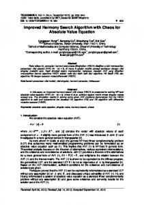
where 𝑁 = 30 and the frequency sampling grid is set to 𝐿 = 10𝑁. The design results including designed impulse response, magnitude response, phase response, phase error response, and group delay response are shown in Figure 1. As observed
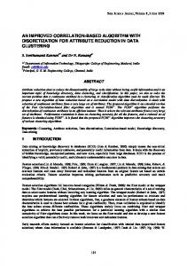
from the analysis of computations and accuracy for Toeplitzplus-Hankel matrix, the proposed technique achieves the same performance as those of the Kidambi method [13] and the least-squares method, whereas the computational complexity can be reduced considerably. Comparison of the design performance with method of [13] and the least-squares method is indistinguishable; we just show the proposed design results. Figure 1(a) shows the design impulse response. The design magnitude response of the IIR all-pass filter is plotted in Figure 1(b). It is obvious that the proposed method achieves unit magnitude response at the bands of interest. The error response of magnitude response can be seen in Figure 1(c). The maximum magnitude peak error response is approximately 6.6613 × 10⁻¹⁵ , which is very small. Figures 1(d) and 1(e) illustrate the phase response and error phase response, respectively. The constant desired group delay response and the designed one are compared at Figure 1(f). The maximum peak phase error response is 0.022 rad and the maximum peak group delay response is 0.5544. Moreover, the maximum pole radius is 0.9301, so the designed IIR all-pass filter not only is stable but also achieves excellent performance with effectiveness. In order to compare the computational efficiency of the proposed technique, a Hilbert transformer with 𝜔𝑜 = 0.04𝜋, 𝜔𝐿 = 0.94𝜋, and varying filter lengths from 𝑁 = 40 to 𝑁 = 240 are designed. Figure 2 shows the comparison ofCPU design time required for the computations of associated matrices with efficient method in [13]. It is evident that the proposed closed-form expressions for the computations of the Toeplitz-plus-Hankel matrix grow very slowly as the filter length increases. However, the design CPU time of the robust and efficient method [13] increases rapidly as compared to the proposed method when the filter is long. This is because the proposed closed-form expressions depend only on the filter length while the Kidambi [13] method depends both on filter length and on frequency sampling grid. Therefore, it is concluded that the proposed method has the superiority in efficiency as well as design accuracy. Although the Hilbert transformer is only considered for the derivation of the closed-form expression, the proposed method can also be applied to the quadrature mirror filter design that generally with a constant phase response 𝜃𝑑 (𝜔) = −𝑘𝜔 is required [26].
6. Conclusion The least-squares design of all-pass IIR filter can be formulated by solving a system of linear equations and the associated matrix can be further represented as a Toeplitzplus-Hankel form. This system of linear equations can be solved using efficient algorithms with 𝑂(𝑁2 ) complexity. Based on the trigonometric identities and sampling the frequency domain uniformly, this paper presents a computationally more efficient and closed-form expressions for the simplification of Toeplitz-plus-Hankel matrix. As a result, not only the design accuracy can be achieved, but also the computational requirements can be reduced greatly.
6
Mathematical Problems in Engineering
Magnitude response
Impulse response, h(n)
1.5 1 0.8 0.6 0.4 0.2 0 −0.2 −0.4 −0.6 −0.8 −1 0
5
10
15
20
25
1
0.5
0
−0.5
30
0
Index n
Normalized frequency
(a)
×10 8
(b)
−15
0 −5
4
Phase response (𝜋)
Magnitude error response
6
2 0 −2 −4
−10 −15 −20 −25
−6 −8
0.05 0.1 0.15 0.2 0.25 0.3 0.35 0.4 0.45 0.5
0
−30
0.05 0.1 0.15 0.2 0.25 0.3 0.35 0.4 0.45 0.5 Normalized frequency
0
(c)
0.05 0.1 0.15 0.2 0.25 0.3 0.35 0.4 0.45 0.5 Normalized frequency (d)
30.6 ×10⁻⁴ 8 Group delay response
30.4
Phase error response (𝜋)
6 4 2 0 −2 −4
30.2 30 29.8 29.6
−6 −8
29.4
−10 −12
0
0.05 0.1 0.15 0.2 0.25 0.3 0.35 0.4 0.45 0.5 Normalized frequency
0
0.05 0.1 0.15 0.2 0.25 0.3 0.35 0.4 0.45 0.5 Normalized frequency (e)
Proposed method Desired response (f)
Figure 1: A 30th Hilbert transformer. (a) Impulse response. (b) Designed magnitude response. (c) Designed magnitude error response. (d) Phase response. (e) Phase error response. (f) Group delay response.
Mathematical Problems in Engineering
7
Table 1: Comparison of computational requirements for associated matrices. Matrix or vector
Operation
Algorithm Kidambi [13]
Conventional (3𝐿 − 1) 𝑁2 3 𝐿 𝑁2 2 𝐿 𝑁2
Proposed
Q
Addition Multiplication Sine or cosine
T
Addition Multiplication Sine or cosine
(2𝐿 − 1) 𝑁 𝐿𝑁 𝐿𝑁
3𝑁 6𝑁 3𝑁
Addition Multiplication Sine or cosine Addition Multiplication Sine or cosine
(2𝐿 − 1) 𝑁 2𝐿 𝑁 2𝐿 𝑁
(3𝐿 − 1) (2𝑁 − 1) 2𝐿 (2𝑁 − 1) 𝐿 (2𝑁 − 1) (2𝐿 − 1) 𝑁 2𝐿 𝑁 2𝐿 𝑁
3 (2𝑁 − 1) 7 (2𝑁 − 1) 3 (2𝑁 − 1) 3𝑁 5𝑁 3𝑁
Addition Multiplication Sine or cosine
3𝐿𝑁2 − 𝑁2 + 2𝐿𝑁 − 𝑁 3𝐿𝑁2 + 2𝐿𝑁 2𝐿𝑁2 + 2𝐿𝑁
10𝐿𝑁 − 3𝐿 − 4𝑁 + 1 7𝐿𝑁 − 3𝐿 5𝐿𝑁 − 𝐿
12 𝑁 − 3 25 𝑁 − 7 12 𝑁 − 3
H
d
Total
allpass filter, with multirate applications,” IEEE Transactions on Circuits and Systems, vol. 34, no. 4, pp. 378–389, 1987.
1 0.9
[2] P. A. Regalia, S. K. Mitra, and P. P. Vaidyanathan, “The digital all-pass filter: a versatile signal processing building block,” Proceedings of the IEEE, vol. 76, no. 1, pp. 19–37, 1988.
0.8
CPU time (s)
0.7
[3] T. I. Laakso, V. V¨alim¨aki, M. Karjalainen, and U. K. Laine, “Splitting the unit delay: tools for fractional delay filter design,” IEEE Signal Processing Magazine, vol. 13, no. 1, pp. 30–60, 1996.
0.6 0.5 0.4
[4] M. Lang, “Allpass filter design and applications,” IEEE Transactions on Signal Processing, vol. 46, no. 9, pp. 2505–2514, 1998.
0.3
[5] X. Zhang, T. Muguruma, and T. Yoshikawa, “Design of orthonormal symmetric wavelet filters using real allpass filters,” Signal Processing, vol. 80, no. 8, pp. 1551–1559, 2000.
0.2 0.1 0 40
60
80
100 120 140 160 180 200 220 240 Filter length
Kidambi method Proposed method
Figure 2: Comparison of CPU time for a Hilbert transformer with varying filter length.
Acknowledgments The authors would like to thank the editor and anonymous reviewers for their valuable recommendations and comments that truly helped toward an effective presentation of the proposed paper. This work was supported in part by the National Science Council, Taiwan, under Contracts NSC 992221-E-0145-001 and NSC-100-2221-E-0145-005.
References [1] P. P. Vaidyanathan, P. Regalia, and S. K. Mitra, “Design of doubly-complementary IIR digital filters using a single complex
[6] S. S. Lawson and A. Klouche-Djedid, “Technique for design of two-channel approximately linear phase QMF filter bank and its application to image compression,” IEE Proceedings-Vision Image Signal Processing, vol. 148, no. 2, pp. 85–92, 2001. [7] J.-H. Lee and Y.-H. Yang, “Design of two-channel linear-phase QMF banks based on real IIR all-pass filters,” IEE ProceedingsVision Image Signal Processing, vol. 150, no. 5, pp. 331–338, 2003. [8] M. F. Qu´elhas and A. Petraglia, “Optimum design of group delay equalizers,” Digital Signal Processing, vol. 21, no. 1, pp. 1–12, 2011. [9] G. Stancic and S. Nikolic, “Digital linear phase notch filter design based on IIR all-pass filter application,” Digital Signal Processing, vol. 23, pp. 1065–1069, 2013. [10] S.-C. Pei and P.-H. Wang, “Maximally flat allpass fractional Hilbert transformers,” in Proceedings of the IEEE International Symposium on Circuits and Systems, vol. 4, pp. 701–704, May 2002. [11] M. Lang and T. I. Laakso, “Simple and robust method for the design of allpass filters using least-squares phase error criterion,” IEEE Transactions on Circuits and Systems II, vol. 41, no. 1, pp. 40–48, 1994. [12] C.-K. Chen and J.-H. Lee, “Design of digital all-pass filters using a weighted least squares approach,” IEEE Transactions on Circuits and Systems II, vol. 41, no. 5, pp. 346–351, 1994.
8 [13] S. S. Kidambi, “Weighted least-squares design of recursive allpass filters,” IEEE Transactions on Signal Processing, vol. 44, no. 6, pp. 1553–1557, 1996. [14] C.-C. Tseng, “Design of IIR digital all-pass filters using least pth phase error criterion,” IEEE Transactions on Circuits and Systems II, vol. 50, no. 9, pp. 653–656, 2003. [15] S. C. Chan, H. H. Chen, and C. K. S. Pun, “The design of digital all-pass filters using second-order cone programming (SOCP),” IEEE Transactions on Circuits and Systems II, vol. 52, no. 2, pp. 66–70, 2005. [16] Z. Jing, “A new method for digital all-pass filter design,” IEEE Transactions on Acoustics, Speech, and Signal Processing, vol. 35, no. 11, pp. 1557–1564, 1987. [17] M. Ikehara, M. Funaishi, and H. Kuroda, “Design of all-pass networks using Remez algorithm,” in Proceedings of the IEEE International Symposium on Circuits and Systems, pp. 364–367, June 1991. [18] X. Zhang and H. Iwakura, “Design of IIR digital allpass filters based on eigenvalue problem,” IEEE Transactions on Signal Processing, vol. 47, no. 2, pp. 554–559, 1999. [19] K. Rajamani and Y.-S. Lai, “Novel method for designing allpass digital filters,” IEEE Signal Processing Letters, vol. 6, no. 8, pp. 207–209, 1999. [20] S. S. Kidambi, “Closed-form approach to design of all-pass digital filters using cepstral coefficients,” Electronics Letters, vol. 40, no. 12, pp. 720–721, 2004. [21] G. A. Merchant and T. W. Parks, “Efficient solution of a Toeplitz-plus-Hankel coefficient matrix system of equations,” IEEE Transactions on Acoustics, Speech, and Signal Processing, vol. 30, no. 1, pp. 40–44, 1982. [22] P. Delsarte and Y. V. Genin, “The split Levinson algorithm,” IEEE Transactions on Acoustics, Speech, and Signal Processing, vol. 34, no. 3, pp. 470–478, 1986. [23] E. Z. Psarakis and G. V. Moustakides, “An 𝐿 2 -based method for the design of 1-D zero phase FIR digital filters,” IEEE Transactions on Circuits and Systems. I, vol. 44, no. 7, pp. 591– 601, 1997. [24] S. S. Kidambi, “An efficient weighted least-squares design of linear-phase nonrecursive filters,” IEEE Transaction on Circuits and Systems-II, vol. 42, no. 5, pp. 359–361, 1995. [25] Y.-D. Jou and F.-K. Chen, “Least-squares design of FIR filters based on a compacted feedback neural network,” IEEE Transactions on Circuits and Systems II, vol. 54, no. 5, pp. 427–431, 2007. [26] L.-C. Su, Y.-D. Jou, and F.-K. Chen, “An efficient least-squares design of IIR all-pass filter,” in Proceedings of the IEEE Region 10 Conference (TENCON ’09), Singapore, November 2009.
Mathematical Problems in Engineering
Advances in
Decision Sciences
Advances in
Mathematical Physics Hindawi Publishing Corporation http://www.hindawi.com
Volume 2013
The Scientific World Journal Hindawi Publishing Corporation http://www.hindawi.com
Volume 2013
International Journal of
Mathematical Problems in Engineering Hindawi Publishing Corporation http://www.hindawi.com
Volume 2013
Combinatorics Hindawi Publishing Corporation http://www.hindawi.com
Volume 2013
Hindawi Publishing Corporation http://www.hindawi.com
Volume 2013
Abstract and Applied Analysis
International Journal of
Stochastic Analysis Hindawi Publishing Corporation http://www.hindawi.com
Hindawi Publishing Corporation http://www.hindawi.com
Volume 2013
Volume 2013
Discrete Dynamics in Nature and Society
Submit your manuscripts at http://www.hindawi.com Journal of Function Spaces and Applications Hindawi Publishing Corporation http://www.hindawi.com
Hindawi Publishing Corporation http://www.hindawi.com
Volume 2013
Journal of Applied Mathematics
Advances in
International Journal of Mathematics and Mathematical Sciences
Journal of
Operations Research
Volume 2013
Probability and Statistics International Journal of
Differential Equations Hindawi Publishing Corporation http://www.hindawi.com
Volume 2013
ISRN Mathematical Analysis Hindawi Publishing Corporation http://www.hindawi.com
Hindawi Publishing Corporation http://www.hindawi.com
Volume 2013
ISRN Discrete Mathematics Volume 2013
Hindawi Publishing Corporation http://www.hindawi.com
Hindawi Publishing Corporation http://www.hindawi.com
Volume 2013
Hindawi Publishing Corporation http://www.hindawi.com
Volume 2013
Hindawi Publishing Corporation http://www.hindawi.com
Hindawi Publishing Corporation http://www.hindawi.com
Volume 2013
ISRN Applied Mathematics
ISRN Algebra Volume 2013
Hindawi Publishing Corporation http://www.hindawi.com
Volume 2013
ISRN Geometry Volume 2013
Hindawi Publishing Corporation http://www.hindawi.com
Volume 2013