QUT Digital Repository: http://eprints.qut.edu.au/
Parveen, Tania and Ledwich, Gerard F. and Palmer, Edward W. (2007) Induction Motor Parameter Identification from Operational Data. In: 2007 Australasian Universities Power Engineering Conference (AUPEC 2007), 9-12 December 2007, Perth.
© Copyright 2007 (please consult author)
INDUCTION MOTOR PARAMETER IDENTIFICATION FROM OPERATIONAL DATA Tania Parveen Queensland University of Technology 2 George street Garden point Brisbane
[email protected] Ph: (+61 7) 3138 1380
Prof.Gerard Ledwich& Dr. Ed. Palmer Queensland University of Technology 2 George Street Gardens Point Brisbane
[email protected] Ph: (+61 7) 3138 2864
Abstract Among the parameters of an induction motor, the dynamics are largely characterised by Inertia (H) and torque-damping factor (B). It is now simple to get substation bus bar data (current and voltage) by using phasor measurement device. This paper uses that data to identify an induction motor model in frequency domain and from the model of the induction motor one can estimate B and H. In this paper estimation of parameter B and H from the frequency domain model of an induction motor is shown for a fan load by using simulation model and also a 1.5kW real motor in a Queensland University of Technology (QUT) laboratory.
1. Introduction Induction motors undergo transients when voltage, current and speed vary therefore it is important to understand dynamic characteristic of the motor for their influence on power system dynamics. Inertia and torque damping factor are the key influential parameters for the dynamic nature of induction motor. Hence in this paper the value of B and H are estimated from the Bode plot of an induction motor transfer function aiming to study their influence to power system and vice-versa. This frequency domain model is obtained using correlation techniques. Papers [1-20] estimate induction motor modelling and parameters without considering the major effect that load change influence the power system as well power system change effect the load . The authors of those papers have used a feed forward model (power system affects load) but in this paper the feedback loop ( where load is effecting the power system) in addition to the nomal feed forward element is being considered. Paper [2] has considered feedback loop and estimated transfer function of the power system not the transfer function of load. In that paper [2] the author mentioned that it is important to identify the more significant load. Approximately 50-60% of electric energy is consumed by induction motors in a power system therefore the induction motor is a significant load and this paper is interested in the dynamic characteristic of the induction motor. Papers [1-23] consider the changes of the power system as
measurement noise but in this paper the change of power system and change of load are considered as major information to developed the model of the induction motor and the theory for identification of a system under feedback with multiple noise is already developed in paper [23] which is used in this paper. For estimating the parameters of the system, the system model is important. Paper [17] described some model of induction motor and also described that 1st order quasi stationary model is good for determine response to disturbance up to 2 Hz and for disturbances with some higher perturbation frequency the motor can be treated as third order model which neglect the stator transient. Aiming to model induction model in the frequency band which effect the generator oscillation, this paper simulates in time domain. For obtaining time domain the simulation has used a 3rd order induction motor model. After simulation we transfer the 3rd order data to frequency domain. Also we decompose the third order to and equivalent 1st order model by ignoring the rotor transient. Then map the 1st order to steady state algebraic equation to determine the parameter value. There are different types of test methods performed on motor and these are off-site methods, onsite and off-line methods. In off-line, test the motor separately from its application side (no load and locked rotor test) and Onsite and offline methods test are performed with the motor already connected in the industrial setup and supplied by its power converter [4]. On-line
methods are concerned usually with rotor parameter and assume other parameter known [4] .B and H are the main parameter estimated in this paper using an online method in this paper. Also, the on-site method is good for small perturbations and this paper consider small perturbation around steady state of voltage and frequency as input with real and reactive power change as output. An experiment has been conducted up in Queensland University of Technology Laboratory for the purpose of this research .A phasor measurement device has been used for measuring the system transient data and a 16 bit data acquisition card is used to acquire the data. The paper is organized as follows. Section II calculates the induction motor model and introduces the 3rd order model and decomposes the 1st order model from the 3rd order model. Section III describes algebraic equation to identify the parameters. Section IV presents a simulated result in frequency domain and from that plot to estimate the value of B and H. Section V describes the experimental results and section VI the conclusion.
Similarly, reactive power model of induction motor by changing voltage/supply frequency is,
G =
S w1 q G Δq = 1 = Δvs G2 S w1 v
To fit this model to the induction motor model, the 3rd order induction motor is simulated in matlab. Third order model is derived from 5th order by ignoring the stator transient. The equations of third order model in synchronous reference frame are [24],
⎡Ψdr ⎤ ⎡Ψdr ⎤ ⎡Vdr ⎤ ⎡Vds ⎤ + Br ⎢ ⎥ + Cr ⎢ ⎢ ⎥ = Ar ⎢ ⎥ ⎥ ⎢⎣Ψqr ⎥⎦ ⎣Vqr ⎦ ⎣Vqs ⎦ ⎣Ψqr ⎦
ωr =
ωb 2H
(Te − Tl )
Where,
ω r , ωb
Angular velocity of rotor and power system
in rad/s.
Te Electromagnetic torque Tl Load torque
2. Induction motor transfer function [23]
ω r Derivative of rotor angle
The block diagram of the interaction between power system and an Induction motor load is shown in fig.1. W1 is the white noise in frequency or voltage of the power system and W2 is the white noise of the P or Q of the Induction motor. These two variables indicate the disturbance of the power system and the load. The symbol X is the voltage (v) or frequency (f)/angle ( ω ) changes in power system and Y is the real (P) or reactive (Q) power changes of the induction motor load.
Ψdr Derivative of Direct − axis flux Ψqr Derivative of quadrature − axis flux Vds Direct − axis stator voltage Vdr Direct − axis rotor voltage Vqs quadrature − axis stator voltage Vqr quadrature − axis rotor voltage Ar , Br and Cr matrix with fixed components If ignoring the stator transient the 1st order induction motor model is,
⎡Ψdr ⎤ ⎡0 ⎤ ⎡Vdr ⎤ ⎡Vds ⎤ = + + Ar Br Cr ⎢Ψ ⎥ ⎢0 ⎥ ⎢Vqr ⎥ ⎢Vqs ⎥ ⎣ ⎦ ⎣ ⎦ ⎣ ⎦ ⎣ qr ⎦
ωr =
ωb
2H
(Te − Tl )
3. Algebraic Equation Consider here the steady state of induction motor model, as shown in fig .2.
FIG.1 Multinoise feedback model The real power model of the induction motor by changing voltage/ supply frequency is presented here for the voltage case
G=
Sw p Δ p G1 = = 1 Δv G 2 S w1v
Rr: Rotor Resistance X1: stator reactance X2: Rotor reactance X: X1+X2 Xm: magnetizing reactance Pe: Real power of induction motor (p.u) Qe: reactive power of the induction motor (p.u) FIG.2 Steady-state Induction motor circuit diagram
B: Mechanical torque coefficient (p.u)
The slip of induction motor is,
H: Inertia constant (p.u torque/p.u speed)
Sl =
ωs − ωr ωs
Pm: mechanical power (p.u) (1)
From the above circuit, if ignore the mutual inductance, the current equation is, I=
V Rr + R1 + jX Sl
(2)
Using the value of I, real and reactive power of the induction motor is,
By using induction motor continuous state space model (5) and (6) and assuming that the slip of induction motor is working in linear region of torque –speed curve and also input bus frequency is perturbing with white noise, can find out the linear time invariant transfer function
s+Z ΔPe =Kf , s= Laplace transform Δf s+P Where,
Pe =Real (VI*) Qe =Imag (VI*)
(3) (4)
We model the shaft load as linear so the dynamic motion equation is,
Pm =B ω r
(5)
dω r dt
(6)
Pe − P m = 2H
Where
S l : Slip of an induction motor
Kf=
V2 Rr ω s
,
(8)
Here V0, sl0 are the steady state voltage and slip of an induction motor. Z=
B 2H
(9)
zero of the transfer function 2
V0 B P= + 2 H 2 HRr ω s
(10)
pole of the transfer function Similarly
ωs
: Synchronous speed of the bus (P.U)
ωr
: Angular frequency of rotor (P.U)
ΔQe
ωv
=
2 sl 0Vqs2 0 X Rr2ω b
I: Current (P.U) V: Bus voltage (P.U) R1: stator resistance
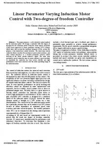
4. Simulation Result
S+ (
B 2H
v qs2 B (S + ) + 2 H 2 HRr ω b
)
Bode plot of 3rd and decompose 1st order from 3rd order using invfreqs -10
3-phase, 10HP motor with following parameters values is used for simulation in MATLAB.
-20
H 0.5
Rr 0.0222
R1 0.0453
X2 0.0322
X1 0.074
Xm 2.042
Magnitude (dB)
B 0.5
-40
rd
st
Frequency domain plot of 3 order and 1 order real power transfer function of the induction motor between V and P is as shown in fig.3
gain
pole
-30
zero
-50 -60 90 45
Phase (deg)
From the plot,
The location of zero is 0.4842
0
-45 -90 -2 10
The location of pole is 78.37
-1
10
0
1
10
10
2
3
10
10
4
10
5
10
Frequency (rad/sec)
The gain is -11db
FIG.4 Bode plot of 1st and 3rd order model
-20logA=-11 Kf=0.2724
ω b = 377 rad / s st
The algebraic equation of 1 order transfer function is, Rr =0.0292. 2
Kf= 1.5
V Rr ω b
Pole-Zero=
Here V=1.414 pu
V2 2 Rr H
V2 H 1.414 * 1.414 H= =0.441 (78 − .48) * 2 * 0.0292 (78-.48) 2Rr=
Bode plot of 3rd and decompose 1st order from 3rd order using invfreqs 0 -10 Magnitude (dB)
-20 -30
Zero=
-40 -50 90
B 2H
B=0.48*2*0.441=0.423 1st order model 3rd order model
45 Phase (deg)
5. Experimental result
0
-45 -90 -2 10
-1
10
0
10
1
10
2
10
3
10
4
10
5
10
Frequency (rad/sec)
FIG.3 Bode plot of 1st and 3rd order model simulated in Matlab The way to find out pole and zero location from 1st order transfer function is as shown in fig.4.
A 1.5kw, 3-phase motor with shaft load of 1HP dc machine is running in the laboratory and a phasor measurement unit with 16bit data acquisition card is used to store the input voltage, current and phase. Real and reactive power is calculated by using these data. Transfer function G (
ΔPe ΔQe , ) is Δω v Δω v
generated by using the theory developed in paper [23]. After transfer function is identified, fit it to 3rd order model and decompose 3rd model to 1st order model. Therefore compare the 1st order model pole and zero location to algebraic equation and estimate the value of B and H. The real motor transfer function shown in fig.5
ΔPe is Δω v
From fig.5
value gets more close to the accurate result. There is a draw back to get the exact value because more difficult to use long sample point because of memory limitations in MATLAB. Estimating parameter from bode plot is a quite accurate and easy method proved by estimated parameter of a real motor in QUT lab. This paper is successful to show that if power system operation data are available, using those data it is easy to plot Bode Plot and from Bode plot it is easy to calculate parameter values. Therefore, it is possible to identify the type of induction motor load in power system.
Kf=0. 8843 Location of pole=0.04 Location of zero=0.002397 Put the values in Equs (8-10), The value of H=7.840 And B=0.0375. Direct measurement of real power from the experiment setup is 0.035pu .As consider the rotor angular frequency is similar to system angular frequency. Therefore the value of B is equal to value of real power. Experimental value of B and Estimated value of B almost exact. MAG
The method used for modelling induction motor is accurate enough to estimate the parameter value. If it is not accurate then parameters value can’t predict the real motor parameters. Also the 3rd order model of a synchronously rotating reference frame is good choice to incorporate dynamic characteristic and variable operating data. In addition the linearized algebraic equation is accurate enough to compare with 1st order fit.
-60 3rdord 1st ord meas
-70
This paper is part of the thesis of “Composite Load Model Decomposition: Induction motors contribution”. Hence future work would be to indetify the frequency domain character of several groups of induction motors and to decompose the groups to parameters for each group of motors. There is also a need to decompose the composite load into (1) constant power load, (2) constant impedance load and (3) frequency dependent load (Induction motor).
pole
magnitude in db
-80
-90
-100
-110
-120 zero -130 -4 10
-3
10
7. References -2
10 frequency inrad/s
-1
10
0
10
FIG.5Bode plot of real,1st order and 3rd motor run in experiment lab
The per unit inertia estimated from bode plot is 7.850s.In kg.m2 the value is 0.954 kg m2.The size of rotor used in experiment lab almost 1kg.Hence the estimation is of the correct order.
6. Discussion The calculated value of B and H from bode plot are close to the exact value. INVFREQZ command has been used for decomposing 3rd order induction model to 1st order model. INVFREQZ command estimates model in frequency domain based on sampling frequency. Hence the accuracy depends on length of the data sequence. The longer the sample set, the
[1] Alonge, F, F. D'Ippolito, et al. "Parameter identification of induction motor model using genetic algorithms." Control Theory and Applications, IEE Proceedings- Vol.145, No.6, pp. 587-593.1995 [2] I.A.Hiskens.J.V.Milanovic (1995). "Load modelling in studies of power system damping." IEEE Trans. Power Sys, Vol.12, pp.255-261, Feb.1997 [3] Jennifer Stephan, John Chiasson. "Real time Estimation of the parameters and fluxes of induction motors." IEEE Trans. Ind Apply, Vol.30, No.3,May/June.1994 [4] Amuliu Bogdan, A. k.. "Identification of variable frequency induction motor models from operating data." IEEE Trans. Energy Conv., vol.17, pp. 24-31, Mar. 2002.
[5] J.Pedra. "Estimation of typical squirrel cage induction motor parameters for dynamic performance simulation."IEE Proceeding.generartion, transmission, distribution, Vol.153.No.2, pp.137146.Mar.2006 [6] De S.Riberio,L.A.Jacobina. "Real time estimation of the electric parameters of an induction machines using sinusoidal PWM voltage waveforms."IEEE Trans .Industry App,Vol. 36,No.3,pp .743754,May/Jun.2000 [7]F.Corcoles, J.Pedra ”Analysis of the induction machine parameter identification." IEEE Trans. Energy Conv.Vol.17, No.2, pp.183-190, Jun.2002. [8]A.Bellini , A. D. c. a. M. L. c. "Parameter Identification for Induction motor simulation." Automatica.Vol. 12.pp. 383-386, 1976 [9] Cecati, C. "On line identification of electrical parameters of the induction motor using RLS Estimation." IEEE.1998 [10] H.Groststollen, "off-line Identification of the electrical parameters of an industrial servo drive system."IAS 31 annual meeting.Vol.1, pp.213-220, Oct.1996 [11] D.J.Mckinnon, C.Grantham (2004). "Investigation of parameter characteristics for induction machine analysis and control." PEMD power electro,mach and drives,Vol.1,pp.320325,April.2004 [12] Rasmus K.Ursem,. "Parameter identification of induction mtoors using stochastic optimization algorithms."CEC evolutionary compu.Vol.2,pp.790796,Dec.2003 [13] Araujo, "Estimation of physical parameters of an induction motor using an indirect method."ISIE Industrial electro, Vol.2, pp.535-540, 2002 [14] M.Pouliquen, J.F.Massieu,M.M'saad "new approach for induction motor parameters estimation."MED control and automation, Vol.11, 2003 [15] Kaiyu. Wang, J. C., Marc Bodson and Leon M.Tolbert. "A Nonlinear least squares approach for Identification of the induction motor parameters." IEEE Trans.Auto Control.Vol.50, pp.1622-1628, Oct.2004 [16] Alonge, F, F. D'Ippolito. "Parameter identification of induction motor model using genetic algorithms." IEE Proceedings Control Theory and Applications, Vol. 145.No.6,pp. 587-593.Nov.1998
[17] Thiringer, t. "Modelling of the induction machines for supply voltage disturbances."ICEM electric machine, Vol.1, pp.41-46, Sept.1994 [18] F T Dai, J. V. m., N Jenkins "The influence of voltage variation on estimated load parameters."CIRED,June.2001 [19] Liu, Q, Y. Chen. “ The load modeling and parameters identification for voltage stability analysis”. PowerCon Power System Technology. Proceedings.Vol.4,pp.2030-2033,2002 [20] Kudla, J. "Use of induction motor steady state characteristic determined by means of the finite element method for parameter estimation of motor nonlinear circuit model."ISEM Proceedings of X International Symposium on Electric Machinery, 2003 [21] Ju, P., E. Handschin,.” Sequential parameter estimation of a simplified induction motor load model. IEEE Trans .Power sys.Vol.11,No.1,Feb. 1996. [22] Xiaoyao Zhou, H.C, Ping Ju . "The third order induction motor parameter estimation using an adaptive genetic algorithm." intelligent control and automation.Vol.2,pp.1480-1484,2002 [23] T. Parveen, G. Ledwich, Ed. Palmer. ”Model of induction motor changes to power system disturbances.” Aupec, Dec.2006 [24] Paul C. Krause,” Analysis of electric machinery and drive systems.” IEEE series on power engineering, 2nd edition.