International Journal of Advanced Science and Technology Vol.68 (2014), pp.49-56 http://dx.doi.org/10.14257/ijast.2014.68.05
Input-Output Linearization of an Induction Motor Using MRAS Observer S. Zaidi, F. Naceri and R. Abdssamed Department of Electrical Engineering, Batna University/ ALGERIA
[email protected],
[email protected] Abstract This paper presents the non-linear control of an induction motor (IM). The objective of nonlinear control is to can control separately flux and the speed, several techniques of control are used for (IM), The technique of control oriented flux (FOC) whichpermits the decoupling between input and output variables, so (IM) is assimilate to continuous current motor , this method has a problem is how exactly oriented the axis d on the flux .However, feedback linearization amounts to cancelling the nonlinearities in a nonlinear system so that the closed- loop (CL) dynamics is in a linear form . A goal of feedback linearizationis to can controlled separately flux and the speed ,the motor model is strongly nonlinear then it’s composed to the autonomous and mono-variables too under systems so every under system presented an independence loop of control for each variables is given . We proposed the MRAS (system adaptive reference model) for speed and rotor fluxobserver. Keywords: input-output modeling, induction motor, LIES derivates, PWM inverter, MRAS
observer
1. Introduction Feedback linearization amounts to cancelling the nonlinearities in a nonlinear system so that the closed- loop (CL) dynamics is in a linear form. A goal of nonlinear control is to can controlled separately flux and the speed, the motor model is strongly nonlinear then it’s composed to the autonomous and mono-variables too under systems, so every under system presented an independence loop of control for each variables is given. Then the induction motors constitute a theoretically interesting and practically important class of non-linear systems. The control task is further complicated by the fact that induction motors are subject to unknown load disturbances and change in values of parameters during its operation. The control engineering community is faced then with the challenging problem of controlling a highly nonlinear system, with varying parameters, where the regulated outputs, besides some of them being not measurable, are perturbed by an unknown disturbance signal [1-3]. The major of the control’s strategiesnecessities know of the precise mechanic speed. There is a lot of inconvenient of employment the speed captor’s then we will exploited the estimators and observers [13-14].We combined the MRAS observer with the input-output linearization control, to verify the behaviour of the control numerical simulations are performed for different operating conditions.
ISSN: 2005-4238 IJAST Copyright ⓒ 2014 SERSC
International Journal of Advanced Science and Technology Vol.68 (2014)
The paper is organized as follows: in Section 2, we give the mathematical input-output model for the induction motor by differentiating the outputs with Lie derivative [5-6] and expressing all states an inputs in terms of these outputs [7], in Section 3, we represented the feedback linearization of IM and in the Section 4 we give the control of flux and speed of linear system, in the five section we give the model mathematic of the observer finally we give the results simulation and the conclusion. Simulation was given by the classic PWM.
2. Model of the Induction Motor The state equations in the stationary reference frame of an induction motor can be writing as [8-9]: ̇ ( ) (1) ( ) With
( ) [ (
[
)
(
]
) ]
: Stator and rotor resistances : Stator and rotor inductances : Mutual inductance : Motor speed. : Rotor flux norm. The variables, which are controlled, are the flux r and the speed . ( ) ( ) ( ) [ ] [ ] [ ] [ ] ( ) ( )
(2)
3. Feedback Linearization of IM 3.1. Relative Degree of the Flux ( )
(
)
(3)
(
)
(
)(4)
(5)
50
Copyright ⓒ 2014 SERSC
International Journal of Advanced Science and Technology Vol.68 (2014)
(
)(
(
) (
)
)(
)
(
)
(6)
(7) The degree of h1(x) is r1=2. 3.2. Relative Degree of Speed ( )
(8) (
[
(10)
(
)
(
)(9)
)(
) (
( )
) ]
(
)(11) (12) The degree of h2(x) is r2=2. 3.3. Global Relative Degree The global relative degree is lower than the order n of the system . The system is siding partly linear zed; we obtain a not observable dynamics of order2. [11] Define the change of coordinates: ( ) ( ) ( )
(13) (
)
{ The derivatives of the outputs are given in the new coordinate system by: ̇ ̇ ̇
(14)
̇ (
{ ̇
)
3.4. Decoupling Matrix The matrix defines a relation between the input (U) and the output (Y(X) is giving by the Expression (15). [
]
( )
( )[
Copyright ⓒ 2014 SERSC
]
(15)
51
International Journal of Advanced Science and Technology Vol.68 (2014)
Where ( ) The decoupling matrix is: ( )
[
] (
and
)
The nonlinear feedback provide to the system a linear comportment input/output [
( )
]
( )
[
( )]
(14)
Where [
[ ]
̈ ( ) ] ̈ ( )
[
]
4. Control Flux and Speed of Lineair System The internal outputs (V1, V2) are definite: ( (
)
(
)
(
)
(15)
)
(16)
The error of the track in (CL) is: ̈
̇
̈ With:
(17) (18) ̇
The coefficients tracking
are choosing to satisfy asymptotic stability and excellent
(
)
( [
52
]
( )
(19)
) [
( )
(20) (
(
(
))]
(21)
Copyright ⓒ 2014 SERSC
International Journal of Advanced Science and Technology Vol.68 (2014)
-
+
+
K21 -
-
-
-
( )
Ce
K22 + -
+
+
A. K 1
-
1
k12
-
-
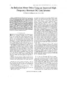
Figure 1. Schema Block of Non-Linear Control
5. MRAS Observer The proposed observer is constituted by too model [10-12-13]: 5.1. Reference Model {
(
)
(
)
(22)
5.2. Adaptive Model ̂
{
̂
(23)
̂
The error is definite by: ̂
̂
(24)
Adaptation mechanism The input of the mechanism is activating by the error: ̂
(
)
̂) ̂
(
(
)(
̂)
(
̂) ̂
(25)
Then we have [ And ̂
∫
Copyright ⓒ 2014 SERSC
]
[
][ Next
]
(
̂) [
]
( ) ( )
53
A M
International Journal of Advanced Science and Technology Vol.68 (2014)
Figure 2. MRAS Observer
6. Simulation Results 1.5 140
120
1
100
flux[wb]
speed[rad/sec]
0.5
80
0
60
-0.5 40
-1 20
0
0
0.1
0.2
0.3
0.4
0.5 time[sec]
0.6
0.7
0.8
0.9
-1.5
1
0
0.1
Figure 3. Speed Rotor [rad/sec]
0.2
0.3
0.4
0.5 time[sec]
0.6
0.7
0.8
0.9
1
Figure 4. Rotor Flux [Wb] 18
6
16 4
14
12 electromagnetic torque[Nm]
stator current[A]
2
0
-2
10
8
6
4 -4
2 -6
0
-8
-2 0
0.1
0.2
0.3
0.4
0.5 time[sec]
0.6
0.7
0.8
0.9
1
0
0.5
1
1.5
2
2.5
3
3.5
time[sec]
Figure 5. Stator Current [A]
Figure 6. Electromagnetic Torque [Nm] 180
1.5
160 1
140
120 rotor speed[rad/sec]
rotor flux[wb]
0.5
0
100
80
60
-0.5
40 -1
20
-1.5
0
0.5
1
1.5
2
2.5
time[sec]
Figure 7. Rotor Flux [Wb]
54
3
3.5
0
0
0.5
1
1.5
2
2.5
3
3.5
time[sec]
Figure 8. Rotor Speed [rad/sec]
Copyright ⓒ 2014 SERSC
International Journal of Advanced Science and Technology Vol.68 (2014)
200
15
10
5
100
stator current[A]
speed rotor and the estimated one[rad/sec]
150
50
0
-5
0 -10
-50
0
0.5
1
1.5
2
2.5
3
time[sec]
Figure 9. Rotor Speed and the Estimatedone [rad/sec]
3.5
-15
0
0.5
1
1.5
2
2.5
3
3.5
time[sec]
Figure 10. Stator Current [A]
7. Simulations Input-output linearization gives us the possibility that we can control separately the speed and the flux, The results are showing in Figure (3-10) represented the simulation, soresponse of speedand the test of the variation of the speed given in Figure 3, the observer gives us the possibility to estimate the speed but with a small delay in the response of the observer and undulation in the Figure 9, the norm of flux remnants to1 [Wb] Figure 4 in the company ofreduction in this value if the speed change in Figure 7 and the current greater than before Figure 10, the regulators of the speed and the flux gives us the choice to control their intensity separately after application the regulation of Hurwitz the simulation is given by MLI inverter.
8. Conclusion The non-linear control gives a good tracking for the speed with basing of its static and dynamic properties. The results show that the decoupling between the parameters of IM is excellent. This technique gives a better amelioration for the performances of system and the MRAS observer give the estimated speed in the future we will change the classic regulators. Specifications of the Induction Motor 1.1KW, 220/380V, 50Hz, 1500 rpm
Parameters of the Induction Motor Rr=3.6 ,J=0.015Kgm2, Rs=8.0 , f 0 .0 0 5 N m s L r 0 .4 7 H
, P=2
Acknowledgements I want offer my appreciation to the professor F.NACERI and The professor R.ABDSSAMED for sustain.
Copyright ⓒ 2014 SERSC
55
International Journal of Advanced Science and Technology Vol.68 (2014)
References [1] [2] [3] [4] [5] [6] [7] [8] [9] [10]
[11] [12]
[13]
E. Delaleau, J. P. Louis and R. Ortega, “Modeling and control of induction motors, Motors”, International Journal of Applied Mathematics and computer Science, vol. 11, (2001), pp. 105-129. J. Chiasson, “Dynamic feedback linearization of the induction motor”, IEEE transactions on automatic control, vol. 38, no. 10, (1993), pp. 1588-1594. R. Marino, S. Persada and P. Valigi, “Adaptive input-output linearizing control of inductions motors”, IEEE transactions on automatic control, vol. 38, no. 2, (1993), pp. 208-221. R. H. Park, “Two Reaction Theory of Synchronous Machines”, AIEE Trans., no. 48, (1929), pp. 716-730 and no. 52, (1933), pp. 352-355. P. Vas, “Artificial –intelligence –based electrical machines and drives: application of fuzzy neural and genetic algorithm-based techniques”, Oxford university press, Inc. New york, (1999). M. K. Maaziz, E. Mendes and P. Boucher, “A new nonlinear multivariable control strategy of induction motors, Article in press, Control engeneering practice, (2001). M. Tarbouchi and H. L. Huy, “Nonlineaircontrol of an induction motor using a DSP, IEEE, 0-8186-73524/96 $05.00© , (1996). M. Bodson, J. N. Chiasson and R. T. Novaki, “Hight performance induction motor control via input-output linearization”, IEEE Trans. Contr. Sys. Tech, vol. 14, no, 4, (1994) August, pp. 33. B. L. Pioufle,”Comparison of speed non linear control strategies for the servomotor”, electric machines and power systems, (1993), pp. 151-169. M. Rashed and A. F. Stronach, “A Stable Back-EMF MRAS-based Sensorless Low Speed Induction Motor Drive Insensitive to Stator Resistance Variation”, Proceeding of IEEE Electric Power Applications, vol. 151, no. 6, (2004), pp. 685-693. J.-J. E. Slotine and W. Li, “Applied nonlineair control”, Prentice-Hall Internationl Editions. M. N. Marwali and A. Keyhani, “A Comparative Study of Rotor Flux based MRAS and Back EMF based MRAS Speed Estimators for Speed Sensorless Vector Control of Induction Machines”, Proceeding of IEEE Industry Application Conference, Thirty-Second IAS Annual Meeting, vol. 1, (1997), pp. 160-166. J. Bocker and S. Mathapati, “State of the Art of Induction Motor Control”, Proceeding of IEEE International Conference on Electric Machines Drives, vol. 2, (2007), pp. 1459-1464.
Author Zaidi Saida, was born in batna, Algeria, in 1971 .I received the Magister degree in electrical Engineering from the Technical UniversityBatna,Algeria, in 2006, Department of Electrical Engineering, Batna University/ ALGERIA.
56
Copyright ⓒ 2014 SERSC