Investigation of a Linear Induction machine for a Railway Braking Application R. Martin, N. Ahmed, M. Kimiabeigi, J. P. Powell, R. Palacin, J. Widmer
Abstract -- Linear induction machines have been employed in the railways for several decades for traction and braking, using an additional “reaction” rail. Linear DC eddy current brakes have also been adopted to provide braking forces by inducing eddy currents in the existing running rails, but at the expense of considerable rail heating. This paper focuses on the concept design of an induction machine that operates at low slips to develop longitudinal braking forces as well as increased adhesion through vertical attractive forces with minimal rail losses. Several candidate topologies were compared using 2D finite element analysis (FEA), whilst 2D and 3D FEA as well as a static test rig were used to analyse and validate the static and dynamic performance of the final design. The simulation and physical test results showed reasonable agreement, and demonstrated that the concept is able to meet the vertical force target at a minimal rail loss. Φ
Index Terms-- Eddy current brakes, Electromagnetic slip, Finite Element Analysis, Force, Induction Machine, Magnetic circuit, Magnetic Flux, Rail transportation.
T
I.
INTRODUCTION
HE low resistance to motion of steel wheels running on steel rails means railways have the potential to be the most energy efficient form of transport for many different applications [1]. However, a key weakness of the steel wheel/steel rail arrangement is low adhesion – effectively the grip between wheel and rail that transmits longitudinal forces for acceleration and braking. The contact mechanics of the rolling contact between wheels and rails is significantly more complex than the sliding friction case, especially in a railway environment [2]. It is affected by the wheel and rail profiles, ambient weather conditions and contaminants such as water, rust, oil and leaves. Nevertheless, a coefficient of adhesion µ can be defined in a similar fashion to the sliding case as the ratio between the instantaneous vertical force at the wheel/rail contact (R) and the actual longitudinal force (F) transmitted: F = µ.R
(1)
This coefficient of adhesion can vary by an order of magnitude, with values around 0.4 on clean dry rails, but falling to 0.04 or lower on damp rails contaminated with leaves [3]. Some locations, such as tree-lined cuttings, are therefore more prone to low adhesion. However, the coefficient of adhesion in any given location can change This work is funded by RSSB under Contract No RSSB1951. N. Ahmed, M. Kimiabeigi, J. P. Powell, R. Palacin and J. Widmer are with School of Engineering, Newcastle University, NE1 7RU (e-mail:
[email protected]) R. Martin is with Nidec SR Drives Ltd., Harrogate HG3 1PR, U.K
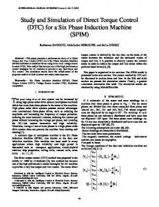
significantly in short periods of time, typically minutes, for example at the onset of light rain. Low adhesion conditions limit the longitudinal force and hence the acceleration achievable by trains, which in turn lengthens journey times. The consequences of low adhesion during braking are more severe: stopping distances are extended, which may result in station overruns or even collisions if trains cannot stop where required. Furthermore, excessive wheel spin or wheel slide also results in long-term damage to wheels and rails. Defensive driving practices therefore call for drivers (or Automatic Train Operation control systems) to brake at rather lower levels than the trains are capable of, to mitigate the risks associated with suddenly encountering significantly lower adhesion levels. However, increasing the braking distance also increases the separation between trains within a network, and so there is a trade-off between reducing the risks associated with low adhesion and maximizing the capacity of the railway network to transport passengers and freight. The most common measures to mitigate low adhesion conditions involve raising the coefficient of adhesion, typically by individual trains applying sand to the rail adjacent to the wheels. Some trains are fitted with track brakes that clamp onto the rail directly to augment the brakes acting on the wheelsets; these track brakes provide additional braking force and help clean the rail. Other options include running specifically-designed maintenance trains that clean the rails with high pressure water jets, and apply friction modifiers (such as Sandite, a mixture of sand and aluminium particles suspended in a gel) to the rail. In the longer term, lineside trees and other vegetation must be managed to reduce contamination during the autumn leaf-fall season. A different way to mitigate low adhesion conditions is to generate additional adhesion-independent braking forces directly. The Japanese superconducting maglev and experimental Fastech 360 Shinkansen trains were fitted with flaps that fold out to increase aerodynamic resistance and augment emergency braking [4]. In Germany, high speed ICE3 trains are fitted with linear eddy current brakes (ECBs), and they have been proposed for adoption elsewhere [5, 6]. These consist of a row of DC electromagnets mounted on the train directly above the rails, with a small airgap of around 6 mm in operation. A linear eddy current brake on an ICE3 train is shown in Figure 1.
Fig 1. A linear eddy current brake in a German ICE3 high speed train
An ECB consists of a conductor (in this case, the rail) moving through a magnetic field. The relative motion induces circular eddy currents in the conductor, creating a drag force that opposes the direction of motion. A key advantage is that the brake does not contact the rail, meaning it does not rely on friction and there is no wear as a result. However, the kinetic energy of the train is dissipated as heat in the rails instead. If the increase in rail temperature over the course of several successive brake applications is excessive, it may cause the rails to buckle and lead to train derailments [7]. This rail heating effect has been a significant reason preventing widespread adoption of ECBs. It can be seen from Equation (1) that an alternative could be to generate additional vertical forces at the wheel/rail interface to augment the weight of the train and allow a greater longitudinal force for a given coefficient of adhesion. The DC-fed ECB design could be modified and fed with variable-frequency three-phase AC instead, effectively forming a short-primary linear induction machine with the rail as the secondary. Matching the supply frequency to the train speed to operate at zero electrical slip would generate attractive forces, while minimising the rail heating compared to ECBs. Although designing an induction machine to run at synchronous speed (i.e. zero efficiency) appears counterintuitive, the purpose is to generate additional vertical forces that increase the effectiveness of the train’s existing braking systems, rather than to generate longitudinal forces directly. This concept is detailed in reference [8], although the principal application there was to improve the stability and safety against derailment of high speed trains running in strong crosswinds. The benefits for traction and braking in low adhesion conditions were mentioned only briefly. No published information about the motor itself or the constraints and design choices inherent in the application to railways was found however. As such, the purpose of this paper is to detail the design and analysis of a short-primary linear induction machine with a narrow solid steel secondary, specifically designed to run at synchronous speed. I. ELECTROMAGNETIC ASSUMPTIONS The general strategy for concept phase is to aim for simplicity of design and winding, to readily demonstrate the achievement of considerable forces without too much consideration of secondary effects such as winding
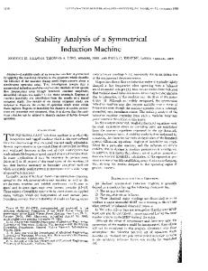
harmonics. Some assumptions were therefore made which are: • The machine’s primary to be constructed from laminated electrical steel of a standard grade M33050A. • In view of the relatively low frequency, iron loss is expected to be a secondary loss mechanism and therefore 0.5mm laminations with good BH characteristics were selected. • Windings were made of copper while the working temperature would be around 100oC. • Active volume of the rail head to be 65mm x 40mm cuboid. This is a simplification of the actual rail head profile. • Width of the primary was assumed to be the width of the rail head; 65mm. Current density of 10A/mm2 continuous could be supported with natural convection. A train at speed will provide some additional forced air cooling, but none was assumed at this stage. • Information on the electromagnetic characteristics of the rail was not readily available and so the data quoted by Wang and Chiueh [9] was used, namely: o Electrical conductivity of rail: 2x10⁶ S/m o Frölich coefficient α: 625 o Frölich coefficient σ: 0.55 Frölich’s formula gives a BH-curve for the rail:
Fig 2. Comparison of the BH-curve for the rail with that for a standard electrical steel
Key elements of the specification which guide the electromagnetic design work are: • Target vertical force 20kN per individual motor; primary • Reduced rail heating compared to ECBs Primary dimensions • Airgap: 6.5 mm • Length: 1500 mm • Width: 130 mm (including the end windings) • Height: 150 mm Rail head dimensions • Width: 65 mm • Depth: 40 mm Train speed
• 80 km/h (Metro) • 200 km/h (Mainline) Electrical supply • 415V 3-phase 50Hz AC supply II.
TOPOLOGY SELECTION AND ANALYSIS
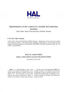
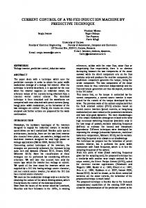
A. Magnetic Sizing and Topology Selection The initial machine topology was developed using basic 2D FEA. The choice of number of poles, pole pitch, rotor and stator sizing and type of windings were all calculated using machine design rules. Each topology was optimized until the target of 20kN vertical force was achieved. A three step analysis sequence was conducted: i. Static tests were carried out with DC (to measure the variation of attractive forces with current) and low frequencies AC supplies (to measure eddy losses in rail) using 2D electromagnetic FEA. ii. 3D FEA was used secondly to investigate the contribution of 3D end effects in the topology. iii. 2D transient with motion FEA was used to give performance projections for the machine in its intended dynamic application. Some basic choices of winding configuration were investigated and a single layer, fully pitched, concentrated winding with open slots was assumed given the importance of simplicity and ease of prototyping at this stage. The candidate design concepts are shown in Figure 3. The vertical forces were modelled for each of the topologies and were fed with a time-varying 3-phase supply equating to peak of 10A/mm2. There is no induced eddy currents allowed in the rotor to idealistically mimic the case where the rotors translates the same velocity as the stator field. This is shown in Figure 4.
Fig 3. Winding concepts a) 4 pole, Fully pitched single layer distributed, 2 slots per pole per phase b) 8 pole, Fully pitched, single layer concentrated, 1 slot per pole per phase c) 8 pole, Single tooth, concentrated d) 4 pole, Single tooth, concentrated e) 2 pole, single tooth, concentrated
From initial analysis, it was clear that the “active” rail depth is a strong determinant of the flux carrying capability
and thus dictates the pole number of a particular winding configuration. This meant that the tooth/slot widths are therefore a balance between carrying the resultant flux per pole, facilitating sufficient MMF (for a given current density) to make full utilization of the steel, and maximizing the effectiveness of the working flux by limiting slot leakage. The slot depth was similarly sized to facilitate sufficient MMF for a given current density whilst limiting slot leakage, and also allowing sufficient core back depth to complete the flux path, making sensible allowance for mechanical issues of location and structural integrity.
Fig 4. Idealized attractive forces from 2D FEA concept modelling
It was seen that a fully pitched, 8-pole, single layer winding with 1 slot per pole per phase (8p/1 (3)) gave the best performance at this stage. The predicted 26kN of force approximately relates to an average air-gap flux density of 0.82T which is reasonable given the considerable airgap and concessions to rapid prototyping. Consideration of the flux density distribution from FEA indicated that the teeth were prone to saturation in initial designs and so the slots were narrowed and deepened to strike a balance in the electric and magnetic loadings. It was realized that some form of tooth tip may help the air gap MMF waveform at the expense of cross-slot leakage and so wider slots were decided to be considered at a later stage. Owing to the saturation effects mentioned, this could lead to a consideration of a higher pole number, though this would lead to a higher electrical frequency which is undesirable from the perspectives of induced rail heating and supply frequency limits. Higher pole numbers and/or slots per pole per phase could yield mechanically unfeasible lamination designs. This topology was easy to vary if optimization is required at a later stage or once 3D FEA is conducted. Once the winding and general topology was set, the lamination profile was designed to optimize the magnetic circuit, avoiding saturation and making good utilization of the available electrical steel and rail components. B. Best design and its performance (2D & 3D) Initial analysis showed the best performing concept design was the third 8 pole, 1 slot per pole per phase design, shown in Figure 3(b3). Its performance was obtained first from 2D FEA and then benchmarked with more representative but computationally more intensive 3D FEA simulations. The simulations were more realistic in that:
• The rail conductivity is included at the value given by [9] • The ends of the stator (primary) are included • Low frequency AC is supplied as a proxy to slip frequency as a way of investigating induced eddy current in the rails In benchmarking this work, a 3D equivalent FEA model was created which exploits tangential flux symmetry at the center of the rail (shown in Figure 5).
Fig 7. Airgap flux density distribution with DC excitation comparing 2D with 3D FEA
III. STATIC AND DYNAMIC PERFORMANCE ANALYSIS Fig 5. 3D FEA model and mesh detail for the concept design (half rail width model only)
A comparison of 2D and 3D forces is shown in Figure 6. The difference between 2D and 3D FEA for this simulated static AC test is a net reduction in attractive force of 12.5% from over 22kN to just under 20kN. This reduction arises due to the fringing and other end effects which tend to reduce the air-gap flux density and associated force. There are two kinds of end effects here: the 3D effect of end-windings in the context of a short active length across the rail and also the entry and exit discontinuities at the front and back of the machine owing to the linearity of the machine by comparison with the continuous nature of a rotating machine (longitudinal end effect). The former is considered through 2D vs. 3D vs test in the static context; the latter is considered in dynamic modelling of the initial transient through to steady state operating by modelling a long secondary (rail) running continuously through the short primary unit.
A. Static Analysis A range of simulations were conducted for varying frequencies. These included: • Longitudinal force vs. peak phase current • Attractive force vs. peak phase current • Input power vs. peak phase current • Attractive force vs. input power • Rail heating vs. peak phase current It is shown in figure 8 that longitudinal and attractive force increased with current (not linearly however and begin to saturate for higher currents). DC operation induced zero rail current in a static test giving rise to zero longitudinal force. In static AC operation, the relative motion of the field and rail induced eddy currents in the rail. These eddy currents interact with the rotating field to give force; higher frequencies meant higher eddy currents and longitudinal forces (to a point).
Fig 6. Attractive forces under DC excitation comparing 2D with 3D FEA
The air-gap flux density, considering (in 3D) the center of the rail width, as well the edge of the stator are shown in Figure 7.
Fig 8. Forces against current for varying frequency
Figure 9 shows input power increased exponentially with the current as (in the static case) it is the sum of the winding loss and the ohmic loss in the rail. The iron loss in the laminations and the AC loss in the windings are negligible due to the low frequency of operation. The rail heating increases with the current following a parabolic, resistance limited, function at smaller currents, whilst shifting into an inductance limited trend at larger currents [10]. The ohmic loss is a function of the rail resistivity and of the currents path within the rail, which possess strong 3D nature.
o Demonstrated measurable characteristics for comparison with lab tests on a static rig; B. Dynamic Analysis This analysis was conducted on a comparably long rail component (FEA model shown in Figure 11) and was modelled at 80km/h and 200km/h to represent urban metro and mainline applications. Figure 11 also shows the appearance of end effects at the entry/exit points of the rail where the field took time to penetrate the rail at entry and induces eddy currents even after the rail has passed the primary.
Fig 11. FEA model for dynamic analysis – eddy current distribution and transient in the rail
Slip was introduced to give rise to generating operation which would exchange some attractive force to bring in longitudinal braking forces. It was expected that the magnitude of eddy currents in the rail would vary with slip and speed. Introducing slip allows to investigate for general braking improvement by exploiting the vertical attraction as well as the conventional longitudinal braking effect of the linear induction machine; zero slip is purely used for vertical force of attractive and not longitudinal forces. Figure 12 shows the Power balance (W) vs. slip (%) in the generating region at speed of 80km/h. Most of the models were run in negative slip which is the generating (braking) region. It is seen that around -3% slip, the mechanical and electrical powers balance and therefore the braking action can supply the losses. The minimum rail heating (Prail) occurs close to zero slip. Fig 9. Input Power and Rail heating against current for varying frequency
Lastly, the attractive force vs the input power is shown in Figure 10 to demonstrate the capability for different input power at different frequencies and as such gives an overview appreciation of the capability of the machine.
Fig 12. Power balance against slip at 80km/h
Fig 10. Attractive force against input power for varying frequencies
In summary, this 2D static modelling: o Gave some proxy indication of performance in actual operation; o Showed good projected performance with respect to the specification;
Figure 13 presents the Attractive (Fy) and Longitudinal (Fx) forces against slip mainly in the generating region at speed of 80km/h. It is seen that the maximum attractive force is seen at zero slip and is in excess of 25kN. Either side of the zero slip (in motoring or generating), attractive force is reduced. Longitudinal force is also minimum around zero slip and increases with slip; it is not perfectly symmetric due to the harmonics present.
Fig 13. Attractive (Fy) and Longitudinal (Fx) forces against slip in generating region at 80km/h
Same FEA was conducted for 200km/h speeds and figure 14 presents the forces in motoring region. The maximum attractive force (Fy) was still at zero slip however now slightly less than 20kN target. This attractive force also reduced quickly as slip was increased. Longitudinal force (Fx) also still showed induction motor characteristics, with a minimum around zero slip.
Fig 14. Attractive (Fy) and Longitudinal (Fx) forces against slip in motoring region at 200km/h
Fig 15. Actual coil implementation
Laminations were supplied in the most readily available grade of M330-50A. Iron loss is not thought to be a significant loss mechanism by comparison with rail heating and copper loss, and a good BH characteristic is useful so this grade was ideal. The laminations are 0.5mm thick and 130 were specified so as to fully utilize the 65mm allowable width commensurate with the rail head width. A stacking factor slightly less than 100% (98% is common) means that the stack is likely to extend outside the rail head very slightly but this is not a problem (within space constraints) and some overhang offers very slight assistance electromagnetically as small amounts of fringing flux may travel to the sides of the rail head. Coils were wound from available 1.8mm copper (slight reduction in fill factor and increase in current density from design levels) onto a former before manual insertion on to the laminations with standard slot liner and protective/insulating tape. The rig suspends the machine on 4 load cells (10kN each, combining to 40kN) above an actual rail sample of 2m length. Two smaller load cells facilitate measurement of translating forces in the direction of the rail. The test rig and the rail sample is shown in Figure 16.
IV. PROTOTYPE TESTING A. Prototype and Test Rig Construction A conventional three phase single layer winding was constructed. The discontinuity of a linear machine necessitates the requirement for two empty slots which reduce the active length of the machine accordingly and gives reduced stator MMF at the ends of the machine. This however reduced the end winding overlapping to two phases in any portion of the end region and can give the ideal compromise in performance. The final design included features for slot wedges (for coil retention) and holes for mounting on the static test rig. 415V AC supply with a controlled rectifier provided a DC bus of 700V (inverter output voltage of approximately 400V RMS). Allowing a factor 2 for headroom, 180 turns per slot with 80A peak was supplied which was equivalent to 10-20A/mm2 with wire diameter to be 1.9mm and coil resistance of 0.8ohms. The actual coil arrangement was devised with an aim of minimizing the coil end windings and maximizing the use of slot area. Practical implementation of this is shown in Figure 15.
Fig 16. Static test rig in place in the university laboratory; Cleaned rail sample for the test rig
B. Testing DC tests were carried out in order to verify the attractive force variation with current. An instant in 3 phase AC operation was emulated by passing current through the phases according to the circuit in Figure 17.
Fig 17. Current passing circuitry – principle of DC test
Current was incremented from 0 to 50A in steps of 5A. The output from the four vertical load cells supporting the primary above the rail was recorded and is shown in Figure 18.
heating – all in the context of longitudinal end effects. This design aims to provide an alternative to linear DC eddy current brakes currently in service. It was shown that we could get good longitudinal braking and vertical attractive forces whilst minimising rail eddy currents at low slip values. This machine can operate at non-zero slip and develop an actual braking force in addition to the increased adhesion; horizontal braking and vertical attractive forces. In this case, it is still a linear induction motor but we can make use of the airgap closing forces as well. Static test results have demonstrated the achievement of attractive forces in excess of the specified 20kN requirement. Agreement between measured forces and the predictions of 2D and 3D electromagnetic FEA is good with slight differences likely due to the end effects. The results confirmed that the operation close to zero electrical slip maximises the vertical forces and minimises the rail heating. Dynamic operation is most effective at lower speed and the application at 80km/h demonstrated this. More detailed design work would realize an improved motor design and the primary aims for a second machine would be to improve the attractive force capability, minimization of rail heating by designing out harmonic content in the magnetic field and minimization of the converter VA requirements. VI. REFERENCES
Fig 18. Load cell output during DC test
Allowing for zero offset and an 8% over-prediction detected in the load-cell setup on calibration, the net attractive force versus current characteristic measure is shown in comparison with 2D and 3D FEA predictions in Figure 19.
[1] Hay W. W. An Introduction to Transportation Engineering. 2nd ed. New York: Wiley; 1977 [2] Olofsson U. and Lewis R. Tribology of the Wheel-Rail Contact. In: Iwnicki S, editor. Handbook of Railway Vehicle Dynamics. Boca Raton, USA: CRC/Taylor & Francis; 2006. pp. 121-141. [3] ‘Schmid, F., Burstow, M. and Clark, S., Wheel-rail best practice handbook. 1st ed. London: A & N Harris; 2010’ [4] Takami H. Development of Small-Sized Aerodynamic Brake for High-Speed Railway. Transactions of the Japan Society of Mechanical Engineers Series B. Vol. 79, no. 803, pp. 1254-1263, 2013 [5] Schykowski J. Eddy-current braking: a long road to success. Railway Gazette International. Vol. 164 no. 5. 2008 [6] Berger KW. Characteristics of Eddy Current Braking. ASME Rail Transportation Division Fall Technical Conference; 12th-13th October 2010; Roanoke, Virginia, USA: American Society of Mechanical Engineers; pp. 47-50. [7] Plu J, Laurans E, Pouligny P, Pison F. Impact of eddy-current brake on high speed line infrastructure. 10th World Congress on Railway Research; 25th-27th November 2013; Sydney, Australia. [8] Konrad H, Heidt H-H, Verfahren und Vorrichtung zur Erhöhung der Normalkraft eines Schienenfahrzeugs European patent EP 1 048542 A3. 2000. [9] P. J. Wang and S. J. Chiueh, "Analysis of eddy-current brakes for high speed railway," Magnetics, IEEE Transactions on, vol. 34, pp. 1237-1239, 1998. [10] M. Kimiabeigi, “On the design of a low cost high performance traction motor with ferrite magnets”, PhD thesis, Newcastle University, 2017.
II.
BIOGRAPHIES
V. CONCLUSION
Richard Martin received the M.Eng. degree in general engineering and the Ph.D. degree in electrical engineering from the University of Durham, Durham, U.K., in 2002 and 2007, respectively. He was a Research Associate at Newcastle University, Newcastle upon Tyne, U.K., from 2012 to 2016. He is currently an Electromagnetic Design Engineer at Nidec SR Drives Ltd., Harrogate, U.K.
In this paper, a linear induction machine design was presented and built to demonstrate static vertical forces and to model all of attractive forces, braking forces and rail
Nabeel Ahmed received his BEng in Electrical and Electronic Engineering from Newcastle University in 2012. He completed his Ph.D. degree from Newcastle University in 2016 in which he designed several
Fig 19: Measured attractive force versus current characteristic, compared with 2D and 3D FEA predictions
Flux switching modulated pole machine topologies to reduce cogging torque in futuristic electric vehicles. Nabeel began his career with Jaguar Land Rover where he worked as a Lead Power Electronics Design Engineer in Electrification Department. He now works as a Research Associate in Newcastle University and specialises in high speed machines, 3D machine topologies and linear induction machines. Nabeel is presently working on improving braking systems in rail and an Airbus project designing a calorimetric system for accurate efficiency measurements. Mohammad (Kia) Kimiabeigi received the BEng, MSc and PhD degrees in electric power engineering from Isfahan University of Technology, Iran 2006, Royal Institute of Technology, Sweden 2008, and Newcastle University, UK 2017. Since 2007 he has been a research engineer at ABB competence center, Sweden, Siemens Wind Power, Denmark, and Siemens Wind Power competence center, UK, and currently a senior research associate at Newcastle University, UK. Dr Kimiabeigi holds 12 granted European and U.S patents, 22 filed patent applications, and over 30 journal and peer reviewed conference publications. During his career, he has been a lead design engineer for R&D projects over a variety of renewable, automotive, and energy sectors, and is currently a principal and coinvestigator in number of research grants, with a total value of over £3 M, where he develops electromagnetic solutions for land, marine, and aerospace applications.
Jonathan Powell received his MEng in Mechanical and Railway Engineering from Newcastle University in 2009, followed by three years in the railway industry, working for Alstom Transport as a mechanical engineer in the UK and Europe. He subsequently returned to Newcastle and completed a PhD in 2016 on the use of linear motors to increase capacity in railway systems, and is currently working as a Research Associate on railway engineering and operations. Roberto Palacin is a senior academic leading the Railway Systems Research Group at New Rail, He has a background in Mechanical Engineering, Design and Railway Systems Engineering. He have been involved in research projects on subjects such as strategic development of transport systems, energy efficiency of urban and mainline rail systems, urban mobility and sustainability, development of innovative railway concepts, innovative intermodal systems, intermodality of the European rail network and development of modular concepts for high-speed. James D. Widmer received the Ph.D. degree in the design of electrical machines from Newcastle University, Newcastle upon Tyne, U.K., in 2013. He joined Newcastle University in 2009 from a senior post in the aerospace industry. He is responsible for the Centre for Advanced Electrical Drives, Newcastle University, which works with industry partners to convert academic research into world-class products. His research interests include high-efficiency permanent magnet machines and rare-earth magnet-free motor topologies.