VOL. 11, NO. 5, MARCH 2016
ARPN Journal of Engineering and Applied Sciences
ISSN 1819-6608
©2006-2016 Asian Research Publishing Network (ARPN). All rights reserved.
www.arpnjournals.com
LOW NOISE AMPLIFIER APPLICATION USING NEGATIVE FEEDBACK FOR ULTRA-WIDEBAND APPLICATIONS N. Saifullah, Z. Zakaria, A. Salleh, M. F. Muhamad Fadzil, S. R. Ab Rashid and A. Bruster Microwave Research Group, Centre for Telecommunication Research and Innovation (CeTRI), Faculty of Electronics and Computer Engineering, Universiti Teknikal Malaysia Melaka (UTeM), Durian Tunggal, Melaka, Malaysia E-Mail:
[email protected]
ABSTRACT This paper presents a design of Ultra Wideband Low Noise Amplifier (LNA) with Negative Feedback and multisection matching network implementing on Microstrip design technique. The design started with selecting a transistor which is Super-low noise InGaAs HEMT MGF4937AM transistor that support ultra-wideband frequencies. In order to achieve ultra-wideband LNA, two different techniques which implementing negative feedback and multisection matching. The uses of negative feedback would degrade the gain while increasing the stability of the system. However, this problem can be overcome by introducing cascaded topology which can increase the gain while leaving the system stable. This LNA design is based on Rogers 4350B microstrip characteristic designed using Advanced Design System (ADS) software. The LNA provides an input return loss (S11) which less than -10 dB and the gain (S21) more than 15 dB and noise figure less than 4dB. UWB LNA can be used on several types of application such as wireless sensor and personal area networks, ground penetrating radars, and medical applications. Keywords: UWB, LNA, microstrip, wideband.
INTRODUCTION Since the rapid growth and development of the high speed wireless transmission, satellite, vehicular as well as ground penetrating radar technology, imaging systems, Ultra-wide band systems turn into a lot more crucial. In recent times, a significant concern in ultrawideband (UWB) technology centers on its possible applicability for short range, high-speed wireless transmission and concerned a significant amount of research and development activity. UWB system can offer a low power, high data rate, low noise, and low cost solution for wireless technology such as wireless personal area network (WPAN) application. UWB system is another method of technology which is used in various applications such as wireless technologies. For example, 802.11b standard and Bluetooth. The advantages of UWB systems are it can support larger number of users and high data rate compared with previous system which is 100Mbps data rate. The most existing proposal for such a standard has target data transmission rates from 22 Mbps to 1320 Mbps with 2 individual bands of 3.1 - 4.85 GHz and 6.2 -10.6 GHz [1]. One approach employs Orthogonal FrequencyDivision Multiplexing (OFDM) in a multiband (MB) radio structure (MB-OFDM) [2], and the other is a single band Direct-Sequence Spread Spectrum (DSSS) radio [3]. In the multiband approach the UWB spectrum is partitioned into several 528-MHz bands. Essentially, the most crucial parameters which represent the communication system capabilities are the receiver sensitivity. The LNA design should achieve high gain flatness, lowest noise figure and acceptable input and output return loss cover for entire band. Several designs of UWB LNA have been proposed using 0.18µm CMOS technology. A design of UWB LNA using two-stages shunt-peaked with notch
filter managed to cover from 3.1 GHz to 10.6 GHz. However, the return loss (S11) does not meet the specification which is less than -10dB [4]. The Newest UWB LNA design proposed by Bhushan R. using microstrip technology, design using negative feedback technique which covers from 0.5 GHz to 6 GHz frequency band [5]. However, the bandwidth covers only 5.5GHz and can be considered as broadband amplifier. Furthermore, A. Serban managed to design UWB LNA cover only for direct sequence spread spectrum (DSSS) or so – called Band Group 1 which operates at 3.1 to 4.8 GHz [6].The design is based on dual-section input and output matching networks in order to achieve better input return loss. In this paper, an ultra-wideband LNA using microstrip technology is proposed with Double stage cascaded implementing multisection input matching with negative feedback. The design meets the requirement of ultra-wideband frequency band which covers from 3.1 GHz to 10.6 GHz.
Figure-1. Transmitter and receiver block diagram.
3295
VOL. 11, NO. 5, MARCH 2016
ARPN Journal of Engineering and Applied Sciences
ISSN 1819-6608
©2006-2016 Asian Research Publishing Network (ARPN). All rights reserved.
www.arpnjournals.com According to Figure-1, LNA is the third block diagram of the receiver system. Wireless transmission is extremely exposed to atmospheric noise and other signal, so the signal transfer from transmitter experience lots of attenuation and distortion. In addition, it is the first system using active component that offers high gain with low noise figure to its frequency band needs which to strengthen weak signal received from transmitter throughout antenna. Furthermore, the use of external cable to connect from antenna to filter and filter to LNA would increase the noise. So, the LNA needs to be designed with lowest noise figure as a trade-off to the external noise. A general LNA is distinguishing in terms of S – Parameter which consists of Gain, Input return loss and Output return loss followed by Noise Figure. However, the stability of the system also need to be considered to prevent oscillation occurred. If oscillation occurs, the signal will oscillate throughout the system and did not process to other block diagram.
Figure-2. Simple block diagram of LNA. Designing LNA consists of several block diagrams such as input matching network, output matching network and biasing network as shown in figure 2. To propose UWB LNA, it is crucial to identify the technique to be used to design the wideband input matching and output matching in order to achieve high bandwidth which can cover ultra-wideband frequencies. A. Serban identified there are two techniques can be used to achieve wideband LNA which by using resistive shunt feedback architecture and multi-section matching network [6]. DESIGN CONCEPT In designing LNA, there are several steps that need to carry out. a) Transistor selection Transistor selection is the first essential step in designing LNA. The researcher need cautiously analyzes the transistor selection maintaining the most important design tradeoffs in mind. The specification needed can be found in transistor datasheet provided by the manufacturer. For this proposed LNA, we identify that the best transistor that could withstand ultra-wideband frequencies from 3.1 to 10.6 GHz is Super-low noise InGaAs HEMT MGF4937AM manufactured by
Mitsubishi. According to datasheet provided the transistor capable to operate until 20GHz. b) Biasing network Biasing network purposely uses to supply optimum Vds and Id according to the datasheet. In datasheet, the manufacturer provides analysis of gain and noise figure with different value of bias point. By selecting optimum DC bias circuit should demonstrate stable thermal performance. Bias point of Vds = 2V and Id = 10 mA is chosen to give optimum performance to LNA. The design of bias network based on voltage divided circuit. c)
Parameter identification In a 2 port network connected to a source and load impedance correspondingly, few types of power gain can be distinct in term of S – parameter and reflection coefficient of source and load. i. Stability condition In LNA design, single power transistor is the method to provide amplification at the desired frequency and the desired linearity. The amplifier must be stable because with unstable amplifier, the signal will not proceed but will oscillate. The stability of the amplifier can be determined by using a K test. If the K factor is greater than unity, at the frequency and bias level in question, then expressions for matching impedances as input and output can be evaluated to give a perfect conjugate match for the device. The set of unconditional stability can be expressed in the formula below [7]. (1) (2) The above equation refers to Rollet’s Criteria for Unconditional Stability which is the important condition. The value of K also can be found using simulation. ii. Noise figure The critical part of designing LNA is about noise optimization. Mainly, the suitable technique to recognize the best optimized noise figure is via noise circle and gain circle which used to verify the input (in = opt) and output reflection coefficient out of the circuit. The noise figure of the transistor can be calculated according to several parameters given by the manufacturer such as Fmin, RN and Yopt at the respective frequency from the equation below [7]. (3)
(4)
3296
VOL. 11, NO. 5, MARCH 2016
ARPN Journal of Engineering and Applied Sciences
ISSN 1819-6608
©2006-2016 Asian Research Publishing Network (ARPN). All rights reserved.
www.arpnjournals.com architecture and multisection L – matching network for input and output matching.
iii. Power, transducer, available power gain
First is power gain, which is the ratio of power dissipated in the load ZL to the power delivered to the input of the two-port network as shown in equation 5. Available power gain is the ratio of the power available from the two-port network to the power available from the source as shown in equation 6. Transducer power gain is the ratio of the power delivered to the load to the power available from the source as shown in equation 7 [7].
a) Negative feedback In order to achieve flat gain and wideband LNA, negative feedback architecture is used [6]. In addition, by implementing negative feedback, transistor stability is improved which is K > 1. However, the feedback resistor reduces the Q-factor of the series equivalent input circuit by count an additional resistive contribution. Furthermore, a slight noise figure has been sacrificing in order to improve other parameters.
(5)
b) Multisection matching The matching is designed based on conjugate matching at the input of the active device will satisfy the condition (ZS= Zopt) in order to achieve the least noise figure. Typically, results in matching network of high loaded Q-values result a narrowband matching network. To design wideband matching network, at least two or more matching type need to be combined at different frequency resulting new topologies such as LC-ladder or Chebyshev filter. In order to overcome the gain drawback from using negative feedback, cascaded amplifier is implemented. For input matching network and output matching network, L – matching network is designed using Smith chart tools provided by Advanced Design System (ADS) software to achieve a better accuracy rather than construct manually. For multisection input matching, the L – matching network is designed at several frequencies inside UWB. In the proposed LNA, the matching is designed at 5GHz, 6.85GHz and 10GHz. Optimum reflection coefficient achieved for 5 GHz is 73.4 + j10.5 Ω while 57.1 + j24.8 Ω for 6.85 GHz and 31.4 + j16.7 Ω for 10 GHz. Figure-3 shows the full schematic diagram of cascaded UWB LNA using negative feedback architecture and multisection matching.
(6) (7) CIRCUIT DESIGN AND SIMULATION According to previous design, it can be conclude the design specification that need to be achieve in order to design UWB LNA. Table-1 below shows the design specification for UWB LNA. Table-1. Design specification.
In the proposed design, two types of techniques are used in order to achieve the design specification occur for UWB LNA which is negative feedback for design
V_DC SRC3 Vdc=5.0 V
V_DC SRC2 Vdc=5.0 V
R R9 R=42.2 Ohm
R R2 R=1.5 kOhm
R R10 R=300 Ohm
R R11 R=42.2 Ohm
L L16 L=7 nH {t} {-o} R= L L L19 L3 R L=0.01 nH {t}L=1.61 nH {t} R1 R= R= R=478 Ohm
L L15 C L=7 nH {t} C1{-o} R= C=100 pF 1
Ref
Term C Term1 Num=1 C6 Z=50 C=X Ohm pF
1
MLIN TL52 Subst="MSub1" W=1.114 mm MLOC L=6.71 mm TL51 Subst="MSub1" W=1.114 mm L=1.519 mm
MLIN TL45 Subst="MSub1" W=1.00386 mm {t} MLOC L=5.4605 mm {t} TL46 Subst="MSub1" W=1.45002 mm {t} L=0.826446 mm {t}
MLIN TL44 Subst="MSub1" W=1.119 mm MLOC L=5.2374 mm {t} TL47 Subst="MSub1" W=1.119 mm L=0.50065 mm {t}
R R12 R=1.5 kOhm
L L17 L=7 nH {t} {-o} R= 1
R C R3 C4 R=140 Ohm {t}C=X pF
R R13 R=300 Ohm L L18 L=7 nH {t} {-o} R=
2 Ref
S2P SNP5
2
S2P SNP4
MLIN TL53 Subst="MSub1" W=1.115 mm L=6.209 mm
C C5 C=X pF
Term Term2 Num=2 Z=50 Ohm
MLOC TL54 Subst="MSub1" W=1.115 mm L=1.115 mm
2
Ref
S2P SNP3
Figure-3. Full schematic diagram of cascaded UWB LNA.
3297
VOL. 11, NO. 5, MARCH 2016
ARPN Journal of Engineering and Applied Sciences
ISSN 1819-6608
©2006-2016 Asian Research Publishing Network (ARPN). All rights reserved.
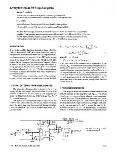
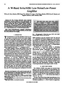
www.arpnjournals.com 3.1 GHz to 10.6 GHz. The noise figure is 3.71 dB to 2.21 dB throughout the frequency band while Figure 6 proves that stability of the circuit is unconditionally stable due to K > 1 for entire frequency band.
40 30 20 10
dB(S(2,2)) dB(S(2,1)) dB(S(1,1))
0
Table-2. Comparison between previous achievements of LNA.
-10 -20 -30 -40 -50 -60 3
4
5
6
7
8
9
10
11
12
freq, GHz
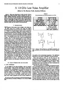
Figure-4. Simulated S – Parameter of UWB LNA. 4.5 4.0
nf(2) NFmin
3.5 3.0 2.5 2.0 1.5 3
4
5
6
7
8
9
10
11
12
freq, GHz
Figure-5. Simulated Noise figure of UWB LNA.
CONCLUSIONS The design of Low Noise Amplifier implemented negative feedback and multisection matching to achieves ultra-wideband frequencies has been proposed, designed and simulated. The designed LNA is biased at Vds = 2V and Id = 10 mA. The result shows that the return loss achieves less than -10 dB for entire band and maximum gain is at 24.95 dB. Furthermore, noise figure is kept lower that 4 dB for entire UWB frequencies. The design is compared with previous achievement which designed using microstrip technology as shown in Table-2. The bandwidth achieves is wider compared with other design while maintaining high gain, low noise figure throughout the frequency band. However, a notch filter can be implemented into the design in order to introduce multifunction capabilities. ACKNOWLEDGEMENTS The authors would like to thank UTeM for sponsoring this work under the research grant, UTeM, PJP/2013/FKEKK (41B)/S01258. REFERENCES [1] N. Koirala, R.K. Pokharel, A.I.A. Galal, H. Kanaya, K. Yoshida. 2011. Design of a Low Noise Amplifier with Integrated Notch Filter for Interference Rejection in Ultra-Wideband Systems. Microwave Conference Proceedings (CJMW), China-Japan Joint. pp. 1 – 4.
Figure-6. Simulated stability of UWB LNA. The simulated S – Parameter, noise figure and stability that describe the amplifier is shown in figure 4, 5 and 6. From figure 4, it is shows that the amplifier gain is 18.2 dB with ±6.75 dB flatness from 3.1 GHz to 10.6 GHz. Furthermore, the input return loss (S11) achieves lower than -10 dB for entire UWB frequencies. This define that the designed amplifier is UWB LNA. Figure 5, shows that the simulated noise figure obtained for the proposed LNA is closed to the minimum noise figure over
[2] P. Heydari. 2005. A Study of Low-Power Ultra Wideband Radio Transceiver Architectures. Proceedings of Wireless Communications and Networking Conference. 2: 758 – 763. [3] M. Z. Win and R. A. Scholtz. 2000. Ultra-Wide Bandwidth Time-Hopping Spread-Spectrum Impulse Radio for Wireless Multiple-Access Communications. IEEE Transactions on Communications. 48: 679-691.
3298
VOL. 11, NO. 5, MARCH 2016
ARPN Journal of Engineering and Applied Sciences
ISSN 1819-6608
©2006-2016 Asian Research Publishing Network (ARPN). All rights reserved.
www.arpnjournals.com [4] C. C. Huang, Z. Y. Huang, Y. C. Wang, Y. T. Hung, M. P. Chen. 2007. 0.18µm CMOS Low-Noise Amplifier with two 2nd-order notch filters for UltraWideband Wireless Receiver. International Workshop on Radio-Frequency Integration Technology. pp. 38 – 41. [5] Bhushan R. Vidhale, Dipali C. Nitnaware, Dr. M. M. Khanapurkar. 2015. Design of Ultra Wideband Low Noise Amplifier with the Negative Feedback using Micro strip Line Technique. IOSR Journal of VLSI and Signal Processing (IOSR-JVSP). 5: 31- 25.
[7] David M. Pozar, 2012. Microwave Engineering 4th Edition, John Wiley. [8] J. F. Chang, Y. S. Lin. J. H. Lee, C. C. Wang. 2012. A Low-Power 3.2 – 9.7 GHz Ultra-Wideband Low Noise Amplifier with Excellent Stop-Band Rejection Using 0.18µm CMOS Technology. Radio and Wireless Symposium (RWS). pp. 199 – 202. [9] F. Osman, N. M. Noh. 2012. Wideband LNA Design for SDR Radio using Balanced Amplifier Topology, Quality Electronic Design (ASQED), 4th Asia Symposium. pp. 86 – 90.
[6] Serban, M. Karlsson, S. Gong. 2006. All - Microstrip Design of Three Multiplexed Antennas and LNA for UWB Systems. Proceedings of Asia-Pacific Microwave Conference. pp. 1106-1109.
3299