Making Modeling Languages Fit for Model-Driven Development Thomas Kühne Darmstadt University of Technology, Germany
[email protected]
Abstract. In this position statement, I argue that modeling languages that aspire to be used in a model-driven development context must fulfill more requirements than traditional notations that have been primarily used for solution sketching. I enumerate some of these requirements, evaluate to what extent they are addressed by the UML, and suggest how the UML could be enhanced in order to become a modeling language that adequately supports model-driven development.
1 Introduction Model-driven Development (MDD) embodies the idea of raising the level of abstraction of artifacts intended to instruct computer hardware. Instead of requiring developers to think and specify at the programming language level—e.g., the level of abstraction afforded by Java—they should be allowed to use more abstract ways of specifying a solution. Conceptually, the notion of model-driven development is therefore just a continuation of the age old computer science trend to increase the productivity of programmers by offering them an increasing number of ways to raise the level of abstraction of their programs. The fact that the next generation of programming languages will, in general, have a visual notation and have traditionally been called “modeling languages”, are just coincidental details of this particular step in programming language evolution. Likewise, yielding advantages regarding “platform independence”—a feature used in marketing MDD—is just a particular incarnation of the age old idea of preferring problem-oriented specifications (addressing the question What?) over solutionoriented realizations (addressing the question How?). Obviously, a modeling language that hitherto has been successfully used for sketching solutions will not automatically be suitable to support MDD. Enabling developers to create high-level artifacts, that are free from any solution-oriented details and can automatically be compiled into machine code (typically involving several intermediate steps), requires more than what typical modeling languages, such as the UML [15], currently have to offer.
2 MDD Language Requirements In the following, I will not attempt to present an exhaustive list of requirements for an MDD language. In particular, I will not further examine a number of requirements that can be considered to be basic. Among such basic requirements for a language are:
II
– a way to ascertain whether sentences in the language are well-formed. – the possibility to assign precise meaning to well-formed sentences of the language. – the property that various partial specifications (e.g., diagrams) will match up to a coherent and complete whole (e.g., a model). – some means to constructively describe structure/behavior for those parts of a specification where declarative descriptions cannot or should not be automatically turned into constructive descriptions. – adherence to basic rules of semiotics regarding its concrete notation. In short, a modeling language aspiring to support MDD must first fulfill the basic requirements of a programming language. 2.1 Standards vs Domain-Specific Approaches Note that in the above I do not require a language to have a standard semantics. In fact, I maintain that the UML’s property of being open to interpretation in some aspects—in the absence of a complete formal specification and with the deliberate introduction of so-called “semantic variation points”—has been a feature of the UML not a bug, significantly aiding its widespread adoption. The less restrictive the meaning of a notation, the more users can choose their own favorite interpretation for it. The increasing popularity of DSL/DSM approaches also testifies to the utility of using a language with concepts and semantics tailored to a particular domain. However, while the choice over tailored concepts and concrete notation is certainly a success factor for DSLs, the ability to define individual well-formedness rules and/or semantics for otherwise identical notation, is surely also of great importance. In general, domainspecificity is attractive for individual developers or small groups since they can then work with a tool that is optimally tailored to their problem domain. The larger the group becomes, e.g., the size of a big organization, the more it will struggle with an inherent disadvantage of this approach: The artifacts, expressed in a highly domainspecific notation and using highly domain-specific concepts, will be next to unreadable to anyone who has not invested the effort of learning the domain-specific language. Hence, the larger a community becomes—certainly at the level of multi-lateral interorganization communication—the more value it will obtain from languages with a standardized notation and semantics. Unfortunately, it is not possible to have your cake (an optimal language) and eat it too (be universally understood). Section 3, however, describes an approach that balances the forces of this specificity dilemma. In the following, I will discuss one issue addressing the organization of specifications, and two issues addressing the absence of any traces of solution-oriented information in problem-oriented artifacts. Although seemingly very different, all three issues have in common that they aim at providing developers with higher levels of abstraction. 2.2 Raising the Level of Abstraction First, as soon as models are no longer sketches that intentionally leave out a lot of required (as opposed to derivable or supplementary) detail, they will become larger and
III
less manageable than they used to be. This implies a need for better means for structuring and handling large models, i.e., some way to solve the specification decomposition problem.
tion rip c s de
ite m
isOfType
ProductType domain metatypes
ItemDescription Pattern
Product
name : String
2 ComputerModel
MonitorModel
processor : String
Computer
pattern artifacts
model types
Monitor
size : String
model instances mt1 : MonitorModel
isOfType
m1 : Monitor
name = "Flat 19" size = 19 1 ct1 : ComputerModel
isOfType
0 c1 : Computer
name = "PC standard" processor = "3.1 Ghz"
domain types
domain instances
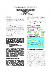
Fig. 1. Representing Types With Objects Second, in order to be solution-independent and hence immune to changes in the choice of realization strategies, models must avoid any polluting traces of solutionoriented choices. However, such pollution easily occurs if a model is annotated with information intended to guide transformations. So-called “marks” [14], if chosen to relate to solution-oriented information, e.g., indicating that a name should be transformed into a string with 40 characters, contaminate the problem-oriented model with solutionoriented information and consequently make it less immune to future changes related to solution technology. This problem appears in its worst form, if marks are imple-
IV
mented with modeling language features that effectively constitute inseparable parts of a model, such as stereotypes or tagged values. It still exists though, even if one manages to “overlay” marks onto the model like a transparency sheet [14], since the correspondence between model elements and their marks must be established somehow and can create a maintenance issue in case the model or the solution technology are changed. In summary, we are facing a polluting transformation phenomenon. Third, another source for model pollution are limitations of solution technologies which are silently carried over to the level of problem specifications without ever being questioned. One such limitation is the traditional restriction of the object-oriented paradigm to only two logical levels, featuring types and instances. Figure 1 shows the design of a computer hardware product hierarchy, which is inspired by an example that Engels et al. used to illustrate the state of the art of modeling with the UML [10]. The design of Fig. 1 uses the “Item Description” pattern [8], also known as “Type Object” [12], and documents common developers practice, supporting a dynamic type level with an ordinary object-oriented programming language. Since types such as “ct1” can be added and removed dynamically, they must be represented as objects and only play the role of types for other objects. This leads to a number of problems [5] wich are too numerous to be listed here, but notice that a lot of what would have been provided by language support, such as object creation with individual constructors, dynamic dispatch, etc. must now be emulated. Also note that while domain instances and types are represented with objects, the domain metatypes are represented as classes (see the circular labels 0–2). The additional machinery required and the muddled up use of UML-supported instantiation (between “ct1” and “ComputerModel”) and usermodeled instantiation (between “c1” and “ct1”) is an inevitable consequence of using a two-level paradigm to accommodate a three-level problem. There is nothing to be said against the model of Fig. 1 if it is meant to model the solution, however, when regarded as a problem-oriented specification, it has to be regarded as featuring accidental complexity [6]. Section 3 describes another version of the model which does not feature this additional accidental complexity, caused by a modeling paradigm that suffers from a two-level limitation.
3 UML Shortcomings and Some Solutions The specificity dilemma mentioned in subsection 2.1 can be addressed by using domaincustomized languages [4], that are constructed according to the following maxime: Start with a standardized language and then incrementally make it specific to your problem domain as much as necessary, but no more specific. This strategy provides developers with an optimally adapted language while preserving the maximum amount of universal communication possible. The UML has had a similar answer to the specificity dilemma with its idea of a “family of languages” [9] for a long time, but never managed to support it well through its profile mechanism, which is limited by the rather weak stereotype concept it is based on. If the UML wants to represent the best of both worlds (modeling standard & domainspecificity) it needs to become a small language intended for building large modeling libraries, i.e., become the “Unified Modeling Library” [3,2], much in the sense of the
V
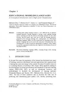
approach described by Griswold et al. for programming languages [11]. The package combination operators of the MOF [16] have hitherto only been used for incrementally specifying the UML but could also be the basis for a number of systematic customization operators. The specification decomposition problem can be addressed with two powerful techniques: refinement and hierarchical structuring. The former can be used to provide simplified versions of otherwise complex artifacts, e.g, as in architecture stratification [1], whereas the latter can be used to organize an artifact based on the principle of aggregation as exemplified by the HOOD method [17]. These techniques do not exclude each other but can be effectively used in conjunction [7]. The UML has added some support for hierarchical decomposition in its recent 2.0 version [15] but still offers only meager support for refinement. It needs to improve in both areas in order to make full-size MDD models manageable. The polluting transformation phenomenon can be addressed by providing guidance to transformations—e.g., categorizing model elements according to the way they need to be transformed—in a manner that only refers to problem-oriented properties of elements. Instead of decorating elements with pieces of information like “EJB Session Bean” and “EJB Entity Bean” one should use categories such as “Transaction” and “Item”. Either the transformation then directly knows about how to map such categories or it may consult a dictionary which provides a mapping from problem-oriented to solution-oriented categories. Note that this way the mapping is still sensitive to changes regarding the transformation of a class of elements (such as all “items”) but, in contrast to a marking approach, is immune at the level of individual model elements. The two-level limitation can easily be lifted by allowing developers to use as many logical modeling levels as they wish. Figure 2 shows a corresponding version of the model in Fig. 1. Note that in Fig. 2, the modeling levels for instances, types, and metatypes align with the domain instances, types, and metatypes respectively. Consequently, the instantiation chain formed by the elements with the circular labels 0–2 only involves a single way of representing instantiation, whereas the model in Fig. 1 uses both UML-instantiation and a user-modeled form of instantiation. In Fig. 2, all UML instantiation relationships have an ontological interpretation, whereas in Fig. 1 the relationships from the domain instances to their UML classes have a linguistic interpretation1 and only the instantiation relationships from the domain types to their UML classes are ontological [13]. In short, the model in Fig. 2 successfully avoids the accidental complexity introduced by the model in Fig. 1. One can expect the Fig. 2 model to be transformed into the Fig. 1 model when proceeding from a problem specification to a solution expressed within a framework with a two-level limitation, but one should never regard the model of Fig. 1 as a faithful representation of the problem and its domain. Allowing users to model at more than two levels is straightforwardly achieved with the Orthogonal Classification Architecture, an infrastructure proposal which cleanly separates the linguistic and ontological dimensions of instantiation, supporting an arbitrary number of ontological levels [2,3]. This infrastructure is also an ideal choice 1
Linguistic instantiation occurs between elements of language usage (e.g., model elements) and elements of language definition (e.g., metamodel elements).
VI model metatypes
name : String
2 ComputerModel
MonitorModel
processor : String
domain metatypes
ProductType
size : String
name = "PC standard" processor = "3.1 Ghz"
mt1 : MonitorModel name = "Flat 19" size = 19
model instances 0 c1 : Computer
m1 : Monitor
domain instances
1 ct1 : ComputerModel
domain types
model types
Fig. 2. Using Three User Modeling Levels
for supporting the concept of a “Unified Modeling Library”, as suggested in section 3. Furthermore, the most expressive way to equip a type model with problem-oriented category markers (see the paragraph on the polluting transformation phenomenon above) is to let model elements be instances of domain metatypes, as shown in Fig. 2.
4 Conclusions In this position statement, I have focussed on a number of shortcomings associated with today’s modeling languages, in particular the UML. I claimed that the specificity dilemma, the specification decomposition problem, the polluting transformation phenomenon, and a two-level limitation prevent today’s modeling languages from opti-
VII
mally supporting MDD. As long as they do not sufficiently address these issues, they will severely hamper the success of MDD and restrict it to application areas where their disadvantages are not applicable or can be tolerated. Interestingly, if used in conjunction with the concept of a “Unified Modeling Library”, the Orthogonal Classification Architecture addresses three of the four aforementioned shortcomings.
References 1. C. Atkinson and T. Kühne. Aspect-oriented development with stratified frameworks. IEEE Software, 20(1):81–89, January/February 2003. 2. C. Atkinson and T. Kühne. Rearchitecting the UML infrastructure. ACM Transactions on Modeling and Computer Simulation, 12(4):290–321, Oct. 2003. 3. C. Atkinson and T. Kühne. Concepts for comparing modeling tool architectures. In L. Briand, editor, Proceedings of the ACM/IEEE 8th International Conference on Model Driven Engineering Languages and Systems, MoDELS / UML, pages 398–413. Springer Verlag, Oct. 2005. 4. C. Atkinson and T. Kühne. A tour of language customization concepts. In M. Zelkowitz, editor, Advances in Computers, volume 70, chapter 3. Academic Press, Elsevier, June 2007. 5. C. Atkinson and T. Kühne. Reducing accidental complexity in domain models. Journal on Software and Systems Modeling, to appear 2008, DOI: 10.1007/s10270-007-0061-0. 6. F. P. Brooks. No silver bullet: essence and accidents of software engineering. Computer, 20(4):10–19, 1987. 7. M. Broy. Compositional refinement of interactive systems modelled by relations. Lecture Notes in Computer Science, 1536:130–149, 1998. 8. P. Coad. Object-oriented patterns. Communications of the ACM, 35(9):152–159, Sept. 1992. 9. S. Cook, A. Kleppe, R. Mitchell, B. Rumpe, J. Warmer, and A. Wills. Defining UML family members using prefaces. In C. Mingins and B. Meyer, editors, Proceedings of Technology of Object-Oriented Languages and Systems, TOOLS’99 Pacific. IEEE Computer Society, 1999. 10. G. Engels, A. Förster, R. Heckel, and S. Thöne. Process modeling using UML. In M. Dumas, W. van der Aalst, and A. ter Hofstede, editors, Process-Aware Information Systems, pages 85–117, New York, 2005. Wiley Publishing. 11. W. G. Griswold, R. Wolski, S. B. Baden, S. J. Fink, and S. R. Kohn. Programming language requirements for the next millennium. ACM Computing Surveys, 28(4es):194–194, 1996. 12. R. Johnson and B. Woolf. Type object. In R. C. Martin, D. Riehle, and F. Buschmann, editors, Pattern Languages of Program Design 3, pages 47–65. Addison-Wesley, 1997. 13. T. Kühne. Matters of (meta-) modeling. Journal on Software and Systems Modeling, 5(4):369–385, 2006. 14. OMG. MDA Guide Version 1.0.1, 2003. Version 1.0.1, OMG document omg/03-06-01. 15. OMG. Unified Modeling Language Superstructure Specification, Version 2.0, OMG document formal/05-07-04, 2005. 16. OMG. Meta object facility (MOF) 2.0 core specification. OMG document formal/2006-0101, 2006. 17. J.-P. Rosen. HOOD — An Industrial Approach for Software Design. ISBN 2-9600151-0-X, 1997.