Design and assembling of a dynamic voltage restorer for small size electrical grids Jorge E. Caicedo, Johnny Posada C.
Juan M. Ramirez
Universidad Autonoma de Occidente Cali, COLOMBIA jrgcaicedo[johnnyposada]@gmail.com
CINVESTAV – del I.P.N. – Unidad Guadalajara Electrical Engineering Department Zapopan, Jal., MEXICO
[email protected]
The technological advance achieved in the power electronics area has allowed the optimization of a diversity of components in the electric power systems (EPS), particularly those related to the energy conditioning field. On the other hand, this tendency has given rise to the appearance of new issues in power transmission and distribution systems, which implies a huge challenge. One of the main concerns in which researches around the world have been focused on is the power quality topic. The adverse effects caused by sags or swells in the manufacture process and sensitive loads have been described in several publications [3]-[6]. Likewise, the voltage harmonics problematic has been broached in manifold publications [7]-[9]. In general, power quality issues become direct factors of economic losses. Hence, the development of custom power systems for improving the power system operation is imperative.
Abstract— According to the open research the conventional dynamic voltage restorer (DVR) is a relevant option in applications concerning voltage compensation. However, despite all the advantages offered by this converter, some disadvantages have delayed its industrial implementation. In order to hasten the maturation process of this technology and to expand its application field, improvements need to be made. This paper presents details of design and performance of an affordable DVR, which is an attractive choice for voltage disturbances at the distribution level. To validate the functionality of the DVR’s topology, a laboratory-scale prototype was implemented. Several experimental tests elucidate the capabilities of the device. Results demonstrate the device’s capabilities to operate under stringent conditions. Keywords- Custom power, DVR, Power electronics, Smart grid.
I.
INTRODUCTION
The development of voltage source converters has been possible largely due to power electronic devices with turn–off capability [17]–[18]. Depending on the way VSCs synthesize the AC voltage, they are divided into two types: (i) with DC– link; (ii) with AC–link. The DC–link type synthesizes an AC voltage from the DC voltage/current when a voltage/current source inverter is employed. When DC energy storage is not used, an additional conversion needs to be performed in the well–known back–to–back configuration AC-DC-AC, usually by means an uncontrolled rectifier [23]. The AC–link type had evolved rapidly taking advantage of converting directly the AC power with the same frequency as usually is required in custom power and FACTS devices but dealing with the magnitude and phase as needed [5], [14]–[17], [20]-[22].
The series compensation device DVR (Dynamic Voltage Restorer) was introduced for voltage sags mitigation and has been adopted as a common solution to the problem. Since its introduction in 1994, several topologies have been developed, along with different control methods and with harmonic compensation purposes [10]-[13]. Grids are primarily based on large power stations connected to transmission lines, which supply power to distribution systems, i.e.; nowadays the grid is hierarchical [1]-[2]. With the advent of computers, sensitive loads, and modern communications, a reliable electricity supply with high quality voltage has become a necessity in distribution systems. There are many ways in which the lack of quality power affects customers. Voltage sags and dips may cause loss of production in automated processes, and may also force a computer system or data processing system to crash. To prevent such events, an Uninterrupted Power Supply (UPS) is often used, which in turn may generate harmonics. The lack of quality power may cause loss of production, and damage to the equipment. As with flexible A.C. transmission systems (FACTS) and other players in transmission systems, power electronics based-devices called custom power systems together with Energy Storage Systems (ESS), Distributed Generation (DG), and smart enduser appliances can be applied to the power distribution systems to increase reliability and quality of power supplied to customers [1].
©2012 SAAEI
Through a conventional DVR topology with DC-link, this paper addresses the more common power quality problems, in particular sags and swells. Together, they account for an important percentage of the power quality disturbances affecting most commercial and industrial customers. Simulation and experimental results are provided to verify the proposed configurations. The hardware implementation of the converter is based on IGBTs and a microcontroller. II.
DYNAMIC VOLTAGE RESTORER DEFINITION
As with flexible A.C. transmission systems (FACTS) devices in transmission systems, power electronics devices can be applied to the power distribution systems to increase
356
reliability and the quality of power supplied to the customers [18]–[19]. The devices applied to the power distribution systems for the benefit of customers are called custom power systems.
electronic switches such as an insulated gate bipolar transistor (IGBT), Fig. 2. The series injected voltage of the DVR is synthesized by modulating the pulse widths of the inverter switches, being necessary to filter the voltage in order to mitigate the switching frequency harmonics generated by the inverter.
Custom power devices are basically compensators, used for active filtering, load balancing power factor correction, and voltage regulation. These devices usually include VSCs controlled by various control strategies and depending on the topology can be divided in three major types: current, voltage, and combined compensation. It is pertinent to mention that nowadays the IEEE Distribution Custom Power Task Force is updating ref. [26], where the authorized definitions are exposed. Some selected devices pertinent to custom power technology are the following. • Distribution Static Compensators [20]. This device can complete current compensation, power factor correction, harmonic filtering, load balancing and also voltage regulation. • Dynamic Voltage Restorer (DVR) [21]. The DVR is a device implemented in low and medium voltage to perform voltage based compensation as voltage harmonics filtering, voltage regulation, and balancing. The conventional DVR topology is constituted by a passive storage element feeding a voltage inverter through a DC-link. In recent years the DVR has gained acceptance among industrial consumers as an efficient and economic solution to mitigate voltage disturbances on power feeders. However, despite its operational advantages, DVR’s capabilities are conditioned by the energy storage device.
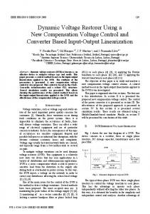
Fig. 1 Conventional schematic of a power distribution system compensated by a DVR.
• Unified Power Quality Conditioner (UPQC) [22]-[23]. The combination of current and voltage compensation in distribution systems is referred to as the UPQC. The conditioning functions of the UPQC are shared by the series and shunt compensators; while its series compensator performs harmonic isolation between supply and load, voltage regulation and voltage flicker/imbalance compensation, the shunt compensator performs harmonic current filtering and negative sequence balancing as well as regulation of the DC-link voltage. A. DVR The DVR is one of the custom power devices that use the power electronics technology, especially the inverter technology and is configured as a series connected voltage controller. A schematic diagram of a conventional DVR incorporated into a distribution network is shown in Fig. 1. vs represents the supply system voltage, vpcc is the voltage at the point of common coupling before compensation, vload is the load voltage after compensation, vdvr is the series injected voltage of the DVR, is is the current demanded to the supply and iload is the current drawn by the load.
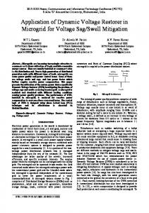
Fig. 2 Dynamic voltage restorer (DVR) operational principle.
The injection of an appropriate voltage under an up-stream voltage disturbance requires a certain amount of active and reactive power supply from the DVR. It is quite usual for the active power requirement of the DVR be provided by the energy storage device in the form of a battery, a capacitor bank or a fly-wheel [12]. In some DVR topologies, there is a shunt connected auxiliary providing energy to the DC-link [25]. The reactive power requirement is generated by the inverter. Power requirements on a DVR depend on the scheme utilized for injecting the compensating voltage. For instance, when the injecting voltage has the same phase angle of the distribution system voltage, the magnitude of the injected voltage is small, but a large active power is required. In the case of the phase invariant voltage injection scheme, the DVR
The restorer typically consists of an injection transformer, the secondary winding of which is connected in series with the distribution line, a pulse-width modulated (PWM) voltage source converter (VSC) bridge connected to the primary side of the injection transformer and an energy storage device connected at the dc-link of the inverter bridge [24]. To control the voltage on the load, the inverter injects the missing voltage in series with the system voltage, using self-commutable
357
idea is to look for the peak within a range near to 90° and 270°. Figure 5 shows an image of the implementation.
injects the missing voltage that keeps the magnitude of the voltage as well as the phase of the supply voltage. This scheme needs a large injected voltage and may cause over injection of reactive power. Finally, if the injected voltage is in quadrature respect to the load current, the DVR does not inject active power. This scheme is highly dependent on the load power factor and can generate a sudden jump of the voltage phase angle. To avoid sudden phase angle jump, the phase of the injected voltage should be gradually changed at the beginning of the compensation as well as at the restoration in order to do not disturb the operation of sensitive loads. A DVR located between the supply and critical loads, has demonstrated excellent dynamic capability for mitigating voltage sags or swells. Each phase can be controlled independently, and the DVR can adjust the magnitude of the load voltage and the voltage phase angle as well. The advantages of the DVR are its fast response and ability to compensate for voltage sag and a voltage phase shift using an inverter system. III.
EXPERIMENTAL RESULTS
In this research the usefulness of the DVR is enhanced through its use as voltage compensator. A prototype has been used to demonstrate its abilities.
Fig. 4 Algorithm to detect the peak of a sine wave.
A. Assembling Figure 3 depicts a scheme of the implemented DVR. A rectifier circuit represents the inverter’s DC source, which generates the compensating AC voltage, able to compensate the load voltage. Thus, the coupling transformer, the inverter, and the rectifier constitute a variable AC source. Adding or subtracting this voltage to the feeder AC source helps to the load voltage constancy. In this prototype, both the coupling and the rectifier’s transformer have a 1:1 relationship.
Fig. 5 Prototype of DVR.
B. Controller As initial study, the behavior under a step signal at the input of the proposed topology is analyzed. Figure 6 displays the result of this study. The main features of this plant are: (i) it is stable; (ii) responds as a first order plant with a significant time delay. The input and output signals shown in Fig. 6 represent the excitation of the SPWM generator and a scaled load voltage peak, respectively. Using this information, an approximate mathematical model can be estimated,
(1) Fig. 3 Details of the implemented DVR
where
; ;
The series injected voltage is SPWM modulated that is generated through a low-cost eight bits’ micro controller. The PI controller and the voltage peak detector algorithm run into the micro controller. The flowchart in Fig. 4, describes the basic principle to search the voltage’s peak value. The basic
; .
Based on the previous analysis, a proportional-integral (PI) controller with an appropriate response may be suggested. Using the mathematical model the PI controller can be tuned
358
to obtain a faster and low over-peak compensator. Figure 7 shows the closed loop behavior of the mathematical model.
depicted.
2,32
magnitud [V]
Input Output
1,441 1.295
1,04 0
13.9 15.9 time[ms]
35
Fig. 6 Step response of the proposed topology.
Fig. 8. DVR’s oscillograms under a voltage sag (feeder’s voltage, the compensating voltage, and load voltage).
Event 2: 23.3% swell In this case, a swell is studied, Fig. 9. The swell is created taken as reference 120Vrms. Thus, voltage of 148 Vrms is attained in roughly 150ms. Then, the controller generates a compensating voltage to mitigate such voltage, taking the load voltage to its nominal value (127 Vac rms).
Fig. 7 Controller’s behavior.
By Euler integration, the transfer function of the controller in the Z domain is calculated, (2) where, represents the control input and the error signal. To run this controller into the microcontroller it is necessary to express equation (2) on the “n” domain, so that (3) where Ts represents the sample time and it depends on the delay of the voltage peak detector algorithm.
Fig. 9 Oscillograms for the swell event
Event 3: Swell and Sag Event 1: 23.3% sag Let’s assume that initially the feeder voltage is 140 Vrms, which the DVR must compensate, so that the load voltage becomes 127 Vrms, Fig. 10. The compensating voltage is in counter-phase respect to the feeder’s voltage. At time t = 50 ms a 36Vrms drop is generated, so that the feeder’s voltage diminishes to 104 Vrms. Then, the controller injects the compensating voltage to have the load voltage constancy.
At time t = 25 ms a 23.3% sudden voltage drop arises (120Vrms to 92Vrms). As a consequence, a compensating voltage is added to the feeder, which compensates the voltage drop approximately in one AC cycle, taking the load voltage to its nominal value (127 Vac rms). In Fig. 8 the feeder’s voltage, the compensating voltage, and load voltage are
359
the DVR is well recognized. This paper deals with applications related to voltage compensation in order to satisfy the future smart grid’s standards.
After that, the feeder voltage goes back to the initial condition, and the controller compensates it accordingly. In Fig. 10 the feeder’s voltage, the compensating voltage, and load voltage are illustrated.
This paper presents details of design and performance of an affordable DVR, which is an attractive choice for voltage disturbances at the distribution level. To validate the functionality of the DVR, a laboratory-scale prototype was implemented. Several experimental tests elucidate the capabilities of the proposed topology. This device is able to satisfactorily compensate sags and swells of about 25% of the nominal voltage. Deeper events may be compensated if greater CD capacitor and a robust controller are used, including power factor handling, which implies a more complex control strategy. ACKNOWLEDGMENT J. M. Ramirez thanks CONACyT under grant 167933. REFERENCES [1] [2]
Fig. 10 Oscillograms for the swell-sag-swell event. [3]
In this transient, the controller must compensate a swell-tosag and vice versa. This requirement makes visible the settling time. Figure 11 shows a detail of the event. Notice the similar behavior between the closed loop mathematical model and the actual plant; in the actual plant does not appear the little overpeak exhibited in the mathematical model.
[4]
[5]
[6]
[7]
[8] [9]
[10]
[11]
Fig. 11 settling time
[12]
These events try to demonstrate that the DVR is able to satisfactorily compensate for common disturbances in distribution systems. Thus, this device may be a good choice to operate into the future smart grid. IV.
[13]
CONCLUSIONS
[14]
The dynamic voltage restorer has evolved rapidly and represents a good choice for alleviating problems related to power quality in distribution systems. Thus, the importance of
[15]
360
R. M. Strzelecki, and G. Benysek, Power Electronics in Smart Electrical Energy Networks, Editorial Springer London, 2008 pp. 1-11. H. Farhangi, “The path of the Smart Grid” IEEE Power and Energy Magazine; December 2009, Vol. 8, pp. 18-28. S. Chen: “DSP-Based control of static power quality compensators in industrial power systems,” Ph. D. Dissertation, Department of Electrical and Computer Engineering, Concordia University, Québec, March 2005. Semiconductor Equipment and Materials International, “SEMI F47-200 Specifications for semiconductor processing equipment voltage immunity”, in SEMI Standards, www.semi.org, Mountain View, CA 2000. D. M. Lee: “A voltage sag supporter utilizing a PWM-Switched autotransformer,” Ph. D. Dissertation, School of Electrical & Computer Engineering Georgia Institute of Technology, Atlanta GA, April 2004. Gerhard Linhofer, Philippe Maibach, and Francis Wong: “Power quality devices for short term and continuous voltage compensation”, International Power Quality Conference 2002, Singapore, 2002. Y. S. Kim, J. S. Kim and S. H. Ko: “Three-phase three-wire series active power filter, which compensates for harmonics and reactive power,” IEE Proceedings Electric Power Applications, vol. 151, no. 3, pp. 276-282, May 2004. S. Bhattacharya: “High Power Active Filter Systems,” Ph. D. Thesis, University of Wisconsin-Madison, 2003. Zheng Zhou, “Simulation and Control of Active Filter,” M. Sc. Thesis, Department of Electrical and Computer Engineering, University of Manitoba, Winnipeg-Manitoba, November 2003. J. G. Nielsen, F. Blaabjerg, and N. Mohan, “Control strategies for dynamic voltage restorer compensating voltage sags with phase jump”, in Proceedings IEEE Applied Power Electronics Conference and Expositions, APEC’01, vol. 2, pp. 1267-1273, 2001. M. J. Newman, D. G. Holmes, J. G. Nielsen and F. Blaabjerg, “A dynamic voltage restorer (DVR) with selective harmonic compensation at medium voltage level,” in Conference Record IEEE-IAS Annual Meeting, vol. 2, pp. 1228-1235, 2003. E. K. K. Sung, S. S. Choi, and D. M. Vilathgamuwa: “Analysis of series compensation and DC-Link voltage controls of a transformerless selfcharging dynamic voltage restorer”, IEEE Transactions on Power Delivery, vol. 19, pp. 1511-1518, 2004. D. M. Vilathgamuwa, C. J. Gajanayake, P. C. Loh, and Y. W. Li, “Voltage sag compensation with Z-source inverter based dynamic voltage restorer,” in Conference Record IEEE Industry Applications Conference, 41st Annual Meeting, vol. 5, pp. 2242-2248, 2006. F. Mancilla-David and G. Venkataramanan, “A pulse width modulated AC link Unified Power Flow Controller,” in Proceeding of the 2005 IEEE Power Engineering Society Genera Meeting, PES-GM, San Francisco, California, 2005. P. Gamboa, J. F. Silva, S. Ferreira Pinto and E. Margato: “Predictive optimal matrix converter and flywheel energy storage,” IEEE Industrial
[16]
[17]
[18] [19]
[20]
[21]
Electronics 35th Annual Conference, IECON’09, pp. 759-764, Porto, Portugal, Nov. 2009. B. Wang and G. Venkataramanan: “Dynamic voltage restorer utilizing a matrix converter and flywheel energy storage,” IEEE Transactions on Industry Applications, vol. 45, pp. 222-231, Jan-Feb 2009. J. C. Rosas Caro, “Simple Topologies for power conditioners and FACTS controllers,” Ph. D. Dissertation, CINVESTAV Unidad Guadalajara, MEXICO, 2009. P. Thomsen, “Application and control of CUPS in the distribution grid,” Institute of energy technology, Aalborg University, vol. 3, 1999. R. Strzelecki, G. Benysek: “Active electrical energy conditioners for individual customers,” PES Conference, Warsaw University of Technology Press, vol. 1, pp. 27-34, 2003. A. Valderrabano and Juan M. Ramirez, “A novel VSC behind the StatCom,” Electric Power Components and Systems, 38:1161–1174, 2010. Jose M. Lozano, “DVR’s Topologies matrix converter-based for improving power quality in distribution systems,” Ph. D. Dissertation, CINVESTAV Unidad Guadalajara, MEXICO, February 2011.
[22] H. Fujita, H. Akagi, “Unified power quality conditioner: the integration of series and shunt active filters,” IEEE Transactions on Power Electronics, vol. 13, no. 2, pp.315-322, 1998. [23] M. Aredes, K. Heumann, E. Watanabe, “An universal active power line conditioner,” IEEE Transactions on Power Delivery, vol. 13, no. 2, pp. 1453-1460, 1998. [24] N. A. Samra, C. Neft, A. Sundaram, and W. Malcom: “The distribution system dynamic voltage restorer and its applications at industrial facilities with sensitive loads” in Proc. Power Conversion Intell. Motion Power Quality, Long Beach, CA, Sept. 1995. [25] T. Jimichi, H. Fujita, and H. Akagi: “Design and experimentation of a dynamic voltage restorer capable of significantly reducing an energystorage element”, in Conf. Record Industry Applications Conference, 14th IAS Annual Meeting. 2005. [26] IEEE Distribution Custom Power Task Force, Guide for the Application of Power Electronics for Power Quality Improvement on Distribution Systems Rated 1 kV Through 38 kV, 2011.
361
Powered by TCPDF (www.tcpdf.org)