Proc. EUROSIM 2007 (B. Zupančič, R. Karba, S. Blažič)
9-13 Sept. 2007, Ljubljana, Slovenia
MODIFIED BROYDEN METHOD FOR NOISE VISUAL SERVOING Mirjana Bonković1, Aleš Hace2, Mojmil Cecić1 1
University of Split, Faculty of Electrical Engineering, Mechanical Engineering and Naval Architecture, 21000 Split, Ruñera Boškovića bb, Croatia 2 University of Maribor, Faculty of Electrical Engineering and Computer Science, Slovenia
[email protected] (Mirjana Bonković) Abstract Uncalibrated, model free, robot visual servoing has been widely applicable in robot vision due to minimal requirements related to calibration and robot kinematic’s parameters. The numerical quasy-Newton methods offer a theoretical background for problem solving, which has been proven hard as the real system has been influenced with the noise. Consequently, additional attention has to be paid which assured stability and the robustness of the proposed method. In this paper we have introduced a new, modified Broyden method for nonlinear optimization problem solving. Modified Broyden method has been achieved applying the variable parameter, which values depend on the Broyden matrix convergence condition. In this paper the standard nonlinear optimization technique (Broyden methods for nonlinear equation solving) has been adopted according to Broyden matrix convergence condition and applied for visual servoing control problem which, due to the noise regularly present in the real systems, could be hardly control by the pure Broyden itself. The developed algorithm is verified by simulations for uncalibrated vision-guided robotic control and compared with four methods from literature, which have usually been used for the similar purpose. Modified Broyden method shows performance improvement over previous methods and is more robust in the presence of noise.
Keywords: Uncalibrated visual servoing, Jacobian estimation, Broyden matrix convergence Presenting Author’s biography Mirjana Bonković received the B.S., M.S., and PhD. Degrees in electrical engineering from the University of Split, Split, Croatia, in 1990, 1994, and 200, respectively. Since 1991, she has worked at the Faculty of Electrical Engineering, Mechanical Engineering and Naval Architecture, University of Split, where she currently serves as associate professor. She was a visiting student at Robotics Research Group, University of Oxford, U.K., in 1995, and Visiting Research Fellow at the Institute of Robotics, University of Maribor, Slovenia, in 2004. Her research interests are image processing, pattern recognition, robot vision and bio-mimetic systems.
ISBN 978-3-901608-32-2
1
Copyright © 2007 EUROSIM / SLOSIM
Proc. EUROSIM 2007 (B. Zupančič, R. Karba, S. Blažič)
1
∆f= J (q)* ∆q
Introduction
One of the first and still today very efficient solutions was offered by Jägersand [1] in which he formulated the visual servoing problem as a nonlinear least squares problem solved by a quasi-Newton method using Broyden Jacobian estimation. Stability is ensured using thrust region method. The similar principles have also been applied for multiple camera model-based 3-D visual servoing [3].
The rest of the paper is organized as follows. In Section 2. the uncalibrated, model free, image base visual servoing problem is presented with a short review of the standard approaches which can be used for solving the mentioned type of problems. We have also specified what our contributions are over the previous methods. Section 3. described the novel method which results with the performance improvement and higher robustness in the presence of noise. In Section 4. we have compared the efficacy of the novel method with four earlier defined methods in solving the defined visual tracking problems, while Section 5. concludes the paper.
If the target is moving, the system model has encountered the error not only as a function of robot poses but also of the pose of a moving objects. Consequently, Piepmeier [2] suggests use of dynamic quasi-Newton with recursive estimation scheme for Jacobian calculation. Recently, the generalized secant method has been proposed [5] based on the population of iterates which improves the servoing based on the acquired information from past iterates to calibrate at the best the model of a nonlinear function. In this paper we have adopted the standard Broyden method, which take the control over the robot joint to position the robot tip into the static point or to track the moving target along the unknown trajectory. It is worth to accentuate that in this paper the standard nonlinear optimization technique (Broyden methods for nonlinear equation solving) has been adopted according to Broyden matrix convergence condition and applied for visual servoing control problem which, due to the noise regularly present in the real systems, could be hardly control by the pure Broyden itself. The developed algorithm is verified by simulations for uncalibrated vision-guided robotic control and compared with four methods from literature, which have usually been used for the similar purpose.
Theoretical background
2.1. Approaches to the problem solving The main goal of the visual servoing is to move the robot tip (or mobile robot) to a certain pose with respect to particular objects or features in images. Based on the error signal domain, two types of visual servoing system could be defined: image base visual servoing (IBVS) and position based visual servoing [4]. The first one assumes that the error is defined in 3D (task space) coordinates, while IBVS is based on the error which is defined in terms of image features. The specification of an image-based visual servo task involves determining an appropriate error function f, such that when the task is achieved, f=0 [4]. Visual servoing problem could be formulated as a nonlinear least squares problem in which the goal function F is defined as:
F=
1 f (θ , t ) T f (θ , t ) 2
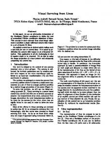
2.2. The control scheme In this paper we are interested in robot visual control in a fixed camera configuration. Fig.1. shows the structure of the visual servo system used in this paper. Here, so called image-based visual servoing is considered, in which the error signal that is measured directly in the image, is mapped to the robot actuators' command input. In our earlier paper [16], as well as in [17], the control law has been developed minutely.
(1)
where f (θ , t ) is an appropriate error function, which could be expressed as:
ISBN 978-3-901608-32-2
(2)
In (2) J is the Jacobian matrix, which relates the rate of change in the image space with the rate of change in the task space. The Jacobian could be identified analytically based on the camera calibration parameters, depth estimation, and the number of features parameters related to number of degrees of freedom the robot has to be controlled. Another approach assumes that visual servoing algorithms have been independent of the hardware types of configuration (robot and camera). Such approach is model free visual servoing which we have described in this paper.
In this paper we have introduced a new, modified Broyden method for nonlinear optimization problem solving which performances have been considered through the model free, uncalibrated image base visual servoing system with fixed imaging. Such systems have been widely applicable in robot vision due to minimal requirements which has to be known related to calibration and robot kinematics’ parameters. Also, reduced set of system parameters guaranties that the system has not been error prone. Up to now, there are numerous examples which successfully use described approach for robot visual servoing [1], [2], [3], [1013]. In this paper, modified Broyden method has been achieved applying the variable parameter, which values depend on the matrix convergence condition. Modified Broyden method shows performance improvement over previous methods and is more robust in the presence of noise.
2
9-13 Sept. 2007, Ljubljana, Slovenia
2
Copyright © 2007 EUROSIM / SLOSIM
Proc. EUROSIM 2007 (B. Zupančič, R. Karba, S. Blažič) Here, for the clarity reasons, we reply that the visual controller is constructed in order to determine the joint velocities q as:
2.3. The modified Broyden algorithm The visual servoing problem has been formulated as a nonlinear least squares problem [1], [2] and it could be solved using quasi-Newton based methods, which consider at each iteration the linear model.
•
q = J + Ke
9-13 Sept. 2007, Ljubljana, Slovenia
(3)
+
where J , K, and e are the pseudoinverse of the Jacobian matrix J that relates joint coordinates with image features, control gain, and the error signal that is obtained by comparing the desired and current image feature parameters, respectively.
Broyden [6] proposed the most successful class of quasi-Newton methods based on the secant equations, imposing the linear model Lk +1 to exactly match the nonlinear function at iterates
x k and x k +1 , that is
Lk +1 ( x k ) = F ( x k )
(8)
Lk +1 ( x k +1 ) = F ( x k +1 )
Subtracting these two equations and defining and we y k = F ( x k +1 ) − F ( x k ) and s k = xk +1 − x k obtain the classical secant equation: Bk +1 s k = y k
(9)
If the dimension n is strictly greater than 1, there are an infinite number of matrices Bk +1 satisfying (11). The “least-change secant update”, proposed by Broyden, could be desbribed as:
Fig.1. Visual servoing blok diagram.
•
use constraint expressed with (9), which result with the following update formula
•
f =Jq
Bk +1 = Bk + λs kT
(4)
where J is a compound of a robot and image Jacobian.
•
(5)
that after rearrangement finally yields decoupled closed loop dynamics of first order (6). •
f + Kf = Kf
d
(6)
However, the compound Jacobian J depends on the system calibration parameters that are hard to obtain accurately in practical applications. In the proposed visual servoing scheme, the Jacobian J is obtained by the estimation process. The Broyden algorithm can be used for on-line estimation of the Jacobian matrix.
(or to attenuate the oscillations and/or deviations from the referent trajectory due to the noise), it is possible to force smaller Jacobian update by introducing the factor η [7], [8], as:
Bk +1 = Bk + ηk
∧
Then, the update equation of its estimate by (7),
skT sk
(12)
where η is chosen so that for some constant
θ ∈ (0,1),
(7)
where the adaptation constant η is introduced in order to maintain the convergence overcoming the noise problems of the Broyden method [2, 7, 8]. In this paper, we propose to use the algorithm for η calculation that is presented in the next part of this section.
ISBN 978-3-901608-32-2
( yk − Bk sk )skT
J is given
∧
J = J + η (∆f − J∆q )∆q T (∆q T ∆q ) −1
(11)
This method has been proved as successful for visual servoing if an additional technique has been used to improve the robustness and stability of the method. Jägersand [1] demonstrates the robust properties of this type of control using thrust region and Piepmeier [2] develops a recursive dynamic Broyden Jacobian estimation for moving target tracking. In this paper, we have improved the standard method based on the convergence condition, which has to be satisfied for Bk matrix. To prevent singularity of the Bk matrix
If the expression (3) is multiplied by J then we get
J q = JJ + Ke
(10)
minimize Bk +1 − Bk
The relation between joint coordinates and image features is given by (2). The same relation could be rewritten using derivatives (4)
ηk − 1 < θ ,
(13)
and when Bk is nonsingular, so is Bk +1 . In this paper, the value for
ηk
has been determined under the
condition in which the matrix generated by Broydenlike methods converges to B=J(x*), where x* is a
3
Copyright © 2007 EUROSIM / SLOSIM
Proc. EUROSIM 2007 (B. Zupančič, R. Karba, S. Blažič) solution. It has been already verified [7] that convergence of matrix Bk has been assured if: y j − Bk s j ≤ (1 + θ ) 2
k− j
(µk , j + σ k , j ) s j
y j − Bk s j − η k
{
σ k , j = max{σ p | j ≤ p ≤ k }, for
sp
skT sk
(14)
(
}
)
2
2
, s q = xq − x p
(15)
BB =
( yk − Bk sk )skT s skT sk
0 < 1 − θ < η < 1 + θ . Therefore,
The subtraction members,
y j − B j +1 s j ≤ y j − B j s j + ( B j +1 − B j ) s j
This means that (9) holds for k=j+1. Now, assume that (9) holds for some k ≥ j + 1 . Then,
y j − Bk +1s j ≤ y j − Bk s j + (Bk +1 − Bk )s j ≤ (1 + θ )2k − j (µk , j + σ k , j ) s j + ηkσ k s j (17) ≤ (1 + θ )2k − j (µk , j + σ k , j + σ k ) s j from which follows (18)
(18)
For the whole proof, we reference to [7]. In this paper, we use (17) for the convergence condition due to the fact that the values at (k+1) instance ( Bk +1 , σ k +1 ),
been accompanied with a big noise, while the other member of the equation Bk s j , has been less
have been unknown. In this paper, we use (17) for the convergence condition. From (13), (14), (15) and (17), (0< η k 1 . Our simulations show that for η k > 1 , the system is not stable. Contrary, for η k < 1 ,
ηk
presented from the simulations described in detail in Section 3. Fig.1.a. represents the y j , while Fig.1.b
solutions is bigger for
represents the signal Bk s j . Figures expose similarity
bigger θ . The most desirable value, which offers η ∈ (0,1) , is θ = 1 . Introducing (12) in (17), the η k
among signals, which is also yield of the assumption from equation (9) embodied in the applied algorithm. Fig.1.c. shows the difference of the signals, completely immersed in noise, while Fig.1.d. shows
can be determined by solving the equation (20)
ISBN 978-3-901608-32-2
y j and Bk s j , as well as
Using (21) assume that the measured signals are noise free, which is not the case with our system. Typical external noises are those from image feature extraction, small scale errors in the tracking and large scale errors in the matching between current and desired features [9]. Regardless the method for feature extraction successfulness, one can expect at least the errors produced as a result of the truncation, which accompanies all the interpreted image data. When object small movements in the image have been feature vector components, such truncation error induces very big noise in comparison to measured image data. For example, if the measured distance among two subsequent position has been truncated to 1 pixel, and real distance belongs to interval [0.5-1.5] pixels, the added noise could belong to an interval of [30-50]%. Consequently, in real situation, y j has
= σ j s j + θ j σ j s j ≤ ( 2 + θ )σ j s j
ηk
(24)
y k and Bk s k , have been influenced with the noise.
(16)
y j − Bk +1s j ≤ (1 + θ ) 2 k +1− j ( µ k +1, j + σ k +1 ) s j
(23)
j
CC = 2k − j (µ k , j + σ k , j + σ k ) s j
)
that we want to calculate the highest possible
(21)
(22)
AA = y j − Bk s j
interval width of possible
(20)
where appropriate vectors are:
and scalar
ηk
≤ ηk
η 2 BB − CC 2 ± 2η k AT B + A = 0
Consequently, (14) can be verified by induction on k . For k = j + 1 , we have from (12) that from (13): B j +1 − B j s j = η ( y j − B j s j ) and
(
sj
Explicit solution has been obtained from (21)
µ k , j = max x p − x q | j ≤ p ≤ q ≤ k
σp =
( yk − Bk sk )skT
2k − j ( µ k , j + σ k , j + σ k ) s j
for all k, j, if k ≥ j + 1 where
y p − Bp s p
9-13 Sept. 2007, Ljubljana, Slovenia
4
Copyright © 2007 EUROSIM / SLOSIM
Proc. EUROSIM 2007 (B. Zupančič, R. Karba, S. Blažič)
values of the signal presented in Fig.1.c. and filtered with zero-order filter for noise removal.
Higher noise level assumes lower values for w1 0 and 0
higher for w2 . With w we estimate the worst possible influence of noise, calculating the highest possible η k , which would maintain the system
Therefore, (21) would not be suitable for the convergence achievement and appropriate validation of the term (21) has to be taken into consideration.
stability. The proposed method results with better performance than most of existed uncalibrated image based visual servoing techniques. Detailed simulations are presented in the next section of the paper.
The assumption which follows has been based on the experience gathered through simulations and includes the estimation of the noise free value of the (20). To adopt the mentioned the term to appropriate signal values, we assume that the main reason due to which we will not be able to maintain that convergence with
ηk
yj
5
estimated matrix
10
15
20
25
30
35
40
45
50
30
35
40
45
50
30
35
40
45
50
30
35
40
45
50
0 -5
0
5
10
15
20
25
yj-Bk*sj
b)
(25) filtered(yj-Bk*sj)
where,
5
a)
Bk +1 . To avoid the problem of
u , v ∈ R n . Then det(I + uvT ) = 1 + u, v
0
5
singularities, we have follow the Lemma presented in [8]: Let
0 -5
is related with singularities in Bk*sj
appropriate
9-13 Sept. 2007, Ljubljana, Slovenia
u, v represents the scalar product.
5 0 -5
0
5
10
15
20
25 c)
2 1 0
0
5
10
15
20
25 time(s)
Applying (25), (12) can be transformed in (26)
det Bk +1 = det Bk (1 − η k ) + η k γ k where
In [8],
γk =
ηk
Bk−1 y k , s k sk
a) One component of the feature vector y j consisted of target movements measured in image b) The Bk s j component of the equation (21)
(27)
2
c) Absolute value of the difference y j − Bk s j
has been chosen such that Bk +1 is
nonsingular. To be more precise, such that:
Fig.1.
(26)
det Bk +1 ≥ θ det Bk ,
ηk
d) Filtered signal y j − Bk s j
has been chosen
1 − ηk ≤ θ
removal
(28)
Eq. (25) shows that introducing two new constants,
3. The algorithms for visual servoing efficiency comparison
w10 , w20 , it is possible to avoid singularity , such that det B k +1 det B k ≥ θ and calculate
3.1. Reference model
(29)
The reference model has been represented with the real system model described in the Section IVA. The Jacobian has been determined as a product of robot and image Jacobian. Having in mind the pin-hole camera model, the relation can be written as:
η k to maintain the convergence. For that
reason we have empirically chosen the constants,
w10 , w20 , such that (27) and (28) holds for all j,k: w10 y j − w20 Bk s j − η k y j − Bk s j − η k
(w y 0 1
k
)
− w20 Bk sk skT sj ≤ skT sk
( yk − Bk sk )skT s skT sk
fx J = JI JR = L* f y
(30)
j
(31)
camera frame, and q1, q 2 are referent joints. The
explicitly using (20) to maintain the convergence. Consequently, appropriate corrections related to AA, BB and CC members (multiplication with w1 0 , w2 0 )
ηk
xc − sin(q1 ) − sin(q 2 ) zc * RPYrot * cos(q1 ) cos(q 2) y 0 − fy c 0 0 z c 0 − fx
where L is the robot link length; f x , f y are camera internal parameters related with focus length, ( xc , y c , z c ) are robot tip coordinates, expressed in the
In fact, the characteristic signals have been appropriately scaled to minimize the noise influence and under such condition, η k has been calculated
have to be applied, which make
for the noise
matrix RPY has been defined with (36), where RPYrot is the orientation part of that matrix. For each iteration, calculated Jacobian serves as a base for control vector calculation.
suitable for
Broyden matrix update. If the system is noise free, then w1 0 = w2 0 = 1 , otherwise w1 0 ≤ 1, w2 0 ≥ 1 .
ISBN 978-3-901608-32-2
5
Copyright © 2007 EUROSIM / SLOSIM
Proc. EUROSIM 2007 (B. Zupančič, R. Karba, S. Blažič)
9-13 Sept. 2007, Ljubljana, Slovenia the least-square problem based on the first term and also to control the numerical stability of the method. The matrix contains weights associated with the
3.2. Dynamic visual servoing model Piepmeier suggests [2] using of dynamic quasiNewton with recursive estimation scheme for Jacobian calculation. A new, dynamic visual servoing model has been proposed in which the qualifier “dynamic” refers to the presence of the error velocity term ( ∂F ( x k +1 ) ). Desired recursive estimation scheme that
arbitrary term
Bk0+1 , and the weights ω ki +1 ∈ ℜ + are
associated with the previous iterates. Equation (33) can be rewritten in matrix form as follows:
∂t
minimizes a cost function based on the change in the affine model, result with the Jacobian update equation:
J k +1
∂F ( x k +1 ) T st s k yk − J k sk − ∂t , = Jk + λ + s k T Pk s k Ps s P 1 = Pk − k k Tk k λ λ + s k Pk s k T
Pk +1
Ω Bk +1 = arg min J ( S k +1 I n × m ) J 0k ×k
where
(32)
ω
(33)
y k = F ( xk +1 ) − F ( xk ) ,
F
on the diagonal for i=0,…,k. The normal
(35) and
The role of the a priori matrix Bk0+1 is to overcome the possible under-determination of problem (35). We have chosen Bk0+1 = B k +1 , which exhibits good properties, so (35) becomes an update formula, which local convergence has been proved in [5]. The weights ω ki +1 , capture the relative importance of each iterate in captures the the population, and the matrix Γ importance of the arbitrary terms defined by Bk0+1 for
the identification of the linear model. The weights have to be finite and Γ must be such that Γ 2 + S k +1Ω 2 S kT+1 is safely positive definite. To ensure this property we seek for a technique to guarantee both the problem of overcoming the under-determination, and numerical stability. Such problem can be solved in a variety of ways [5], but we have found out that the most appropriate is to define it trough simulations as a small positive constant which guaranties positive definition of the term Γ 2 + S k +1Ω 2 S kT+1 .
Population-based generalization prefers to identify the linear model which is as close as possible to the nonlinear function in the least-squares sense.
4. Simulations
At each iteration, the finite population of iterates x0 ....x k +1 are maintained. The method also belongs
4.1. The system
Bk +1 is computed
The simulated system is presented in Fig.2. It consists of components which characteristics are transformed from real experimental setup [10]. During simulations the task has been performed using 2DOF planar parallel manipulator with four revolute joints and a camera that can provide position information of the robot tip and the target in the robot workplace. The robot direct kinematics is given by the following equations,
as
(33)
Lk +1 is defined by (3) and the Bk0+1 ∈ ℜ n×n Bk +1 . The role of the
second term is to overcome the under-determination of
ISBN 978-3-901608-32-2
(34)
s k +1 = ( s k , s k −1 ,..., s 0 ) .
3.4. Population based uncalibrated visual servoing
is an a priori approximation of
2
is a diagonal matrix with weights
Y k +1 = ( y k , y k −1 ,..., y 0 )
This method has been similar to those described in the Section IIB, except the factor η calculation, which has been considered constant. Pure Broyden ( η =1) has been sensitive to noise, so numerous authors suggest use of the factor η [15]. The influence of changing η has been the subject of our earlier works [16], while in this paper we reference the method for the efficacy comparison reasons.
where
)
2
3.3. Broyden visual servoing model with constant modification factor η
2 2 k Bk +1 = arg min ∑ ωki +1F ( xi ) − ωki +1Lk +1 ( xi , J ) + ΓJ − ΓBk0+1 2 F J i =0
Ω 0 Bk0+1 0 Γ
Bk +1 = Bk0+1 + (Yk +1 − Bk0+1S k +1 )Ω SkT+1 (Γ 2 + S k +1Ω 2 SkT+1 )−1
In our simulations we have used P = 5 0 , for the 0 5 first simulation example (Fig.4.a) and P = 4 0 for 0 4 the second example (Fig.4.b) and λ = 0.9 .
to quasi-Newton framework, where
Ω∈ℜ
(
equations of the least-square problem lead to the following formula:
s k = xk +1 − xk , st = t k +1 − t k and 0 < λ ≤ 1 is a weighting parameter.
where
i k +1
k ×1
0k ×n − Yk +1 Γ
6
Copyright © 2007 EUROSIM / SLOSIM
Proc. EUROSIM 2007 (B. Zupančič, R. Karba, S. Blažič)
cos(q1 ) + cos(q 2 ) x = L sin(q1 ) + sin(q 2 )
9-13 Sept. 2007, Ljubljana, Slovenia
(36)
where q1 , q 2 are the robot joint angles, and x is a vector of robot tip coordinates in the Cartesian world coordinate frame (Fig.3). L=0.4m is the length of the robot single link. Translation and rotation of the camera frame with respect to the robot world base frame is given by the RPY homogenous transformation matrix Rc (41). It is rotated around yaxis for 135°, and translated for 1.2, and 1.2 m in y and z direction respectively. 0 0 0 1 0 − 0.707 − 0.707 1.2 . RC = 0 0.707 − 0.707 1.2 0 0 1 0
(37)
Figure 3. Planar 2DOF parallel manipulator The projection of the target positions on the robot workplane is depicted by Fig.4. The initial robot tip position is marked with “0” and the corresponding robot joint angles have the following values: q1 = 30 o , q 2 = 150 o . The initial target position is marked with “0”, and the referent positions are marked “1”, “2”, “3” and “4”. For the first task, the target point positions were generated in the following order: “0”-“1”-“2”-“4”-“3”-“1”-“0”, while for the second task, the target positions were generated through the reference points: “0”-“1”-“2”-“3”-“4”“0”, and the robot passing the points have repeated continuously in the specified time interval of 50 s. The control algorithm has been implemented in SIMULINK model using appropriate S function. For reference trajectory, marked with points “0”-“1”-“2”“3”-“4” in Fig. 4., the rectangle has been chosen with the upper left corner (121,136) and the down right corner (371,336), expressed in the image coordinates. A target start position has been the same as the robot tip start position and it has been moved during simulations with constant speed (measured in pixel/s). The trajectory rectangle has Xmax=250 pixel and Ymax= 200pixel (in the robot world coordinate base frame) width and height, respectively. The trajectory rectangle has the start point Tstart=(x_end0, y_end0) and T_camera=0.033 s has been used in simulations as camera refresh rate (measured in s). Along the curves “1”-“2” and “4”-“3” the y component of the speed has been set to zero. The robot tip starts from the point where target is positioned and marked in Figure 4. as “0”. It is worth to notice that all simulations have been performed under the geometrical noise, which is generated through truncation of image pixels value of the robot tip position, which is a normal procedure in IBVS.
A block named “robot servo” in Fig. 2. represents the robot system dynamics which includes motor, current and velocity-loop dynamics for joints. It has been modeled with the first order open loop transfer function as: G(s)=100/(s+100),
(38)
which means that the velocity-loop is very fast with respect to the sampling interval (Tcamera). The input velocity error has been saturated according to robot specification with limit=0.5. Visual feedback gain has been set to K=5. The “robot servo” itself represents an open loop system, due the direct feedback from joints has been used as input in visual servo controller (Fig.2) for Jacobian update Bk +1 calculation.
4.2. Simulation results In this paper, the image processing node generates the target point applied in the visual task definition within the image. When the robot tip reached the target, the target point was moved to another position in order to provide traveling of the robot tip through the whole robot work plane. The position of the target point determined corners of a “X trajectory” in the image plane.
ISBN 978-3-901608-32-2
7
Copyright © 2007 EUROSIM / SLOSIM
Proc. EUROSIM 2007 (B. Zupančič, R. Karba, S. Blažič)
9-13 Sept. 2007, Ljubljana, Slovenia “deviate” from the shortest possible connection. Fig.7. shows the differences between referent and actual traces of joint speed. The traces have been observed for calculated, robot model Jacobian (Fig.7.a) and for estimated Jacobian based on modified Broyden (Fig. 7b) method. Broyden method results with higher referent joint speed value which, due to saturation limit cause bigger deviations from the referent trajectory (Fig.7.c.d). As one can see from simulations, the modified Broyden method performs the best in comparison with other described methods for uncalibrated visual servoing based on the numerical Jacobian estimation techniques.
5. Conclusion
Fig. 4. Target movement
The image based visual servoing paradigm represents the challenge in the visual controller design due to numerous unknowns present in the system. Such systems have been usefull in an unstructured envinronment which we usually have in the real world. In this paper we have presented the novel method which is based on the convergence of the Broyden matrix condition and which performs better, for the specified task, than several well-known visual servoing techniques with similar characteristics. Although all methods have been declared as quasyNewton based, simulation shows that additional attention have to be paid in overwhelming the unwanted system characteristics. Consequently, appropriate method’s improvement yields the uncalibrated visual servoing paradigm [17] which offers the solution for typical task solving. Piepmeier offers the integral solution for moving target tracking in which two advances have to be taken into consideration: dynamic update which takes into account the target speed and the recursive solution which is the noise resistant. Population based approach has been proven as a numerical method which performances are superior over the similar quasy-Newton methods. It is also suitable for noise environment and it can be supplemented with dynamical update from Piepmaier. Although we have not presented in this paper, it is worth to mention that Jegersand use classical Broyden update with thrust region to improve the stability. Although the thrust region trades the speed for accuracy, Jegersand results have been experimentally confirmed as very succesfull. Finally, presented new method, which has been based on the purely mathematical condition related with Broyden matrix convergence, results with excellent performance. Except the paper presents theoretical and simulation performances of the new method, it represents the clear simulation expose of the typical methods performance obtained through
We have started our simulations performing the described task using reference robot model. As one can expected, the robot tip traces presented in Fig.5a, perfectly follows the desired curve. In comparison with the ideal reference model results, the next simulations have been performed with proposed, modified Broyden method, based on the convergence condition fulfillment (Fig.5.b). We have used 0 constants w1 0 = 0.44, w2 = 2.22 for the both task presented in the Fig.5. The robot tip tracks the goal trajectory tightly. Although the small deviations can be observed in the lower right corner, trajectory visual inspection exposes very good performance in comparison with other techniques described in this paper, which are uncalibrated dynamic visual servoing (Fig.5.c), the population based quazy-Newton like method (Fig.5.d) and “ordinary” Broyden with constant η (Fig.5.e.). The traces of the Jacobian norm have been presented in the third column of the Fig.5., for each of the mentioned methods respectively, for the task described in the second column. It can be observed from the curves that the biggest correlation exists among referent and specific methods traces of the Jacobian norm for the Broyden and the modified Broyden method. Calculated correlation coefficients are 0.54, 0.172, 0.46, 0.5674 for Modified Broyden, Piepmeier uncalibrated, population based and pure Broyden method, respectively. The convergence condition, which has been introduced in the modified Broyden method, reduces the correlation but it improves the stability and the robustness of the method. One of the strongest improvements which has been achieved with a presented method could be obtained for static point positioning. Fig.6. shows the traces of the robot tip trajectory while it approaches to the stationary point (371,336). The modified Broyden results with the straightest line which connects the start and the target point, while all other methods
ISBN 978-3-901608-32-2
8
Copyright © 2007 EUROSIM / SLOSIM
Proc. EUROSIM 2007 (B. Zupančič, R. Karba, S. Blažič)
9-13 Sept. 2007, Ljubljana, Slovenia
300 350
350 280
300
300
200
250
240
200
150
220
200
150
100
a)
norm Jacobian
v (pixels)
v (pixels)
260 250
150
400
350
300
250
200
180
100
u (pixels)
150
200
25 time(s)
20
15
10
5
0
400
350
300
250 u (pixels)
30
35
40
45
50
360 350
350
Ref. normJ Mod. normJ
340 300
300
250
250
320
200
norm Jacobian
v (pixels)
v (pixels)
300
200
280 260 240 220
150
150
200 100
150
200
400
350
300
250
100
u (pixels)
150
200
250
300
350
180
400
u (pixels)
10
5
0
15
25 time(s)
20
50
45
40
35
30
b) 300
350
350
Ref.normJ Piep normJ 280
300
300
200
norm Jacobian
v (pixels)
v (pixels)
260
250
250
240
200
220
150
200
150 180
100
100
c)
150
200
250
300
350
150
200
250
400
350
300
20
15
10
5
0
u (pixels)
400
25 time(s)
40
35
30
45
50
u (pixels)
360 350
350
Ref. normJ Pop. normJ
340 320
300
300
250
250
200
200
150
150
norm Jacobian
v (pixels)
v (pixels)
300 280 260 240 220 200 180 100
d)
150
200
250
300
350
400
100
u (pixels)
150
200
250
300
350
160
400
u (pixels)
5
10
15
20
25 time(s)
30
35
300
250
200
200
50
300
norm Jacobian
v (pixels)
v (pixels)
250
45
Ref. normJ Broy. normJ
320
300
40
340
350
350
0
280 260 240 220
150
150
e)
200
100
150
200
250
300
350
100
400
150
250
200
u (pixels)
u (pixels)
300
350
400
180
0
5
10
15
20
25 time(s)
30
35
40
45
50
Figure 5. First and the second columns: The tasks in which the robot tip has been sequentially moved through the specified points. The image of the reference curve (solid line) and robot tip curve (dashed line) have been presented for: a) Reference model b) The new, modified Broyden method c) Piepmeier model d) Population based model e) Broyden model with constant
η
Third column: Norm of the Jacobian for the task presented in the second column
ISBN 978-3-901608-32-2
9
Copyright © 2007 EUROSIM / SLOSIM
Proc. EUROSIM 2007 (B. Zupančič, R. Karba, S. Blažič)
[4] S. Hutchinson, G. D. Hager, P. Corke, “A Tutorial on Visual Servo Control”, IEEE Trans. On Robotics and Automation, Vol.12, No.5, Oct 1996.
360
STOP
[5] F. Crittin, M. Bierlaire, “A generalization of secant methods for solving nonlinear systems of equations”, in Proc. 3rd Swiss Transport Research Conference, March 19-21, 2003.
340
320
v (pixels)
300
[6] C.G. Broyden, "A class of methods for solving nonlinear simultaneous equations", Mathematics of Computation 19, pp. 577-593, 1965.
280
260
Piep ModBroy Broy Popul
240
START 220 220
280
260
240
300
320
340
360
[7] Donghui Li, Jinping Zeng, Shuzi Zhou. “Convergence of Broyden-Like Matrix”, Appl. Math. Lett. Vol. 11, No. 5, pp.35-37, 1998, Elsevier Science, Ltd.
400
380
u (pixels)
[8] J.J. More, J.A.Trangenstein. ”On the Global Convergence of Broyden’s Method”, Mathematics of Computation, Volume 30, Number 135, July 1976, pp. 523-540.
u (pixels)
v2 (rad/s)
v1 (rad/s)
Fig.6. Static point positioning for different visual servoing methods
[9] C.-V. Stewart. Robust parameter estimation in computer vision. SIAM Review, 41(3):513-537, September 1999.
2 0 -2 0
5
10
15
20
25
30
35
40
45
50
0
5
10
15
20
25
30
35
40
45
50
[10] K. Hosoda, M. Asada, “Versatile visual servoing without knowledge of true Jacobian”, in Proc. IEEE/RSJ/GI Int. Conf. Intelligent Robots and Systems, Munich, Germany, Sept. 1994, pp. 186-193.
2 0 -2
400 200 0
v (pixels)
9-13 Sept. 2007, Ljubljana, Slovenia
0
5
10
0
5
10
15
20
25
30
15
20
25
30
[11] N.Cowan, J.D.Weingarten, “Visual Servoing via Navigation Functions”, IEEE Tran. Rob. Automat., Vpl.18, pp. 521-533., Aug. 2002.
400 200 0
[12] E.Malis, F.Chaumette, S. Boudet, 2-1/2-D Visual Servoing, IEEE Trans. Robot. Automation, Vol.15, Apr. 1999.
time(s)
Fig. 7. Simulation results: traces of reference (solid line) and actual joint speed (dashed line) for robot kinematic modified Broyden model
[13] J.A.Gangloff, M.F.Mathelin, “Visual Servoing of a 6-DOF Manipulator for Unknown 3-D Profile Following”, Trans. On Robotics and Automation, pp. 511-520, Vol.18, No.4, Aug. 2002.
typical uncalibrated servoing trajectory tracking which could serve as a good base which helps in choosing the appropriate method for the specific task solving.
[14] P. I. Corke, “Visual control of robots, high performance visual servoing”, John Wiley & Sons Inc., 1996. [15] G.Dodds, A.Zatari, R.Bischoff “Uncalibrated Visual Servoing for Full Motion Dextrous Robot Systems with Tracking Cameras”, (http://robotik.w3.rz.unibwmuenchen.de/PDF/UnViSer.pdf)
References [1] M. Jägersand, R. Nelson, “On-line Estimation of Visual-Motor Models using Active Vision”, Proc. ARPA Image Understanding Workshop 1996. [2] J. A. Piepmeier, G. V. McMurray, H. Lipkin “Uncalibrated Dynamic Visual Servoing”, IEEE Trans. On Robotics and Automation, Vol.20, No.1, pp. 143-147, February 2004.
[16] Bonković M., Hace A., Jezernik K., ”A new method for uncalibrated visual servoing”, Proc. of AMC, Istanbul, Turkey, pp.624-629., 2006.
[3] J. Stavnitzky, D. Capson, “Multiple Camera Model-Based Visual Servo”, IEEE Trans. On Robotics and Automation, pp. 732- 739,Vol.16, No.6, Dec. 2000.
[17] Bonkovic M., Hace A., Bovan S., Jezernik K., “Iterative solution paradigms for uncalibrated visual servoing”, Proceedings of 16th Int. Workshop on Robotics in Alpe-Adria-Danube Region-RAAD 2007., Ljubljana, June 7-9, 2007.
ISBN 978-3-901608-32-2
10
Copyright © 2007 EUROSIM / SLOSIM