Since an image-to-image registration approach is easier to accomplish .... domain. The DNs of 10-m SPOT panchromatic data (or other high resolution images).
MUlTISENSOR IMAGE FUSION TECHNIQUES IN REMOTE SENSING Manfred Ehlers Surveying Engineering Program University of Maine Orono, ME 04469, USA Commission VII ABSTRACT Current and future remote sensing programs such as Landsat, SPOT, MOS, ERS, JERS, and the space platform's Earth Observing System (Eos) are based on a variety of imaging sensors that will provide timely and repetitive multisensor earth observation data on a global scale. Visible, infrared and microwave images of high spatial and spectral resolution will eventually be available for all parts of the earth. It is essential that efficient processing techniques be developed to cope with the large multisensor data volumes. This paper discusses data fusion techniques that have proved successful for synergistic merging of SPOT HRV, Landsat TM and SIR-B images. Examples are given for integrative rectification, enhancement of cartographic feature extraction and improvement of spatial resolution. INTRODUCTION Earth observing systems of the future such as the proposed polar orbiting space platforms of NASA, ESA and Japan will likely bring another dimension to remote sensing. A variety of imaging (and non-imaging) sensors will be employed to cover the full range of the electromagnetic spectrum available for remote sensing of the earth (Butler et al., 1986). For example, a 30-m resolution imaging spectrometer will provide image data with a spectral coverage of 0.4 to 2.5 Jlm and a spectral resolution of 9.4 to 11.7 nm (Goetz et al., 1987). This amounts to 196 simultaneously recorded spectral bands. In addition, other sensors will provide information in different spectral bands (e.g., thermal infrared and microwave) and/or at different spatial resolutions yielding data volumes and spectral band combinations for which efficient processing methods are yet to be developed. This multisensor, multispectral, multiresolution, multitemporai information will eventually be available for all parts of the earth and presents a data processing challenge to the remote sensing society that has to be addressed. Integrative processing techniques have to fuse the multiimage information to make it useful for a user community that is concerned with mapping, monitoring and modeling the earth's components (figure 1). This paper presents image fusion methods and algorithms that proved successful for synergistic processing of SPOT High Resolution Visible (HRV),
152
Landsat Thematic Mapper (TM) and Shuttle Imaging Radar (SIR-B) data.
MULTISENSOR REMOTE SENSING IMAGES
CREATION OF MULTISENSOR DATABASES (RECTIFICATION, REGISTRATION, RESAMPLlNG)
Figure_1 . Concept for multisensor image evaluation.
IMAGE FUSION AND INFORMATION EXTRACTION
MAPPING, MONITORING, MODELING
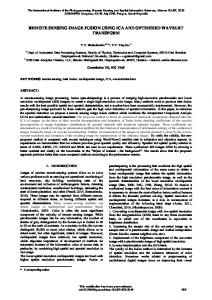
INTEGRATIVE RECTIFICATION Earth-related integrative processing of multisensor image data requires that all images are in register to e,ach other and georeferenced to a common ground coordinate system (figure 2). Rectification and image registration are well known and documented techniques in remote sensing (Bernstein et al., 1983; Welch, Jordan and Ehlers, 1985). Since an image-to-image registration approach is easier to accomplish and allows the utilization of automated or semi-automated image processing techniques it may prove necessary to rectify only goa image of the multisensor dataset to ground control. Other multisensor or multitemporal image data of the same area may be registered to the rectified reference image using automatic or visual techniques (Ehlers, 1984; Luhmann and Ehlers, 1984; Welch, 1984).
Figure 2. Concept of an image database referenced to ground control.
Figure 3. TM and SIR-B image data of southeast Georgia.
153
The validity of this integrative rectification approach could be demonstrated for Landsat TM and SI R-B data. A study area common to satellite scenes of both sensors was identified in the Southeast of the United States (figure 3). This study area encompasses 90 x 90 km and is equivalent to the southeast quadrant (quad 4) of the TM scene. Using a least squares based first degree polynomial rectification algorithm, the TM quad was rectified to the Universal Transverse Mercator (UTM) coordinate system yielding a root-mean-square error (RMSEXY) of ±11.1 m (±0.4 TM pixel) at eleven withheld check points. By contrast, RMSE XY values for the rectified SI R-B dataset were about ±27.5 m to ±30.9 m (±2.2 to ±2.5 SIR-B pixels) at the withheld check points and the ground control points (GCPs), respectively. The major difference in the two datasets is the 'quality' of the images which in return determines the accuracy to which control pOints in the images can be defined. With TM image data, GCPs can be located to a fraction of a pixel whereas for SI R-B data even well defined GCPs such as road intersections cannot be determined to better than ± 1 to ±3 pixels. To overcome these obstacles, an iterative-integrative rectification procedure for low resolution and low signal-to-noise ratio (SNR) data (such as synthetic aperture radar (SAR) or thermal infrared) was developed (Ehlers, 1987). As initial step, the low resolution image is coarsely registered to the rectified reference image of high resolution. Only a few relative control points (tie points) are necessary to accomplish this task. Once the two images are in approximate register, additional tie points can be identified by displaying the images in a flicker mode on the screen of an image processing system. These additional tie points may then be used for a precise registration, and the procedure can be repeated until a sufficient accuracy has been achieved (figure 4).
REFERENCE IMAGE RECTIFICATION INITIAL REGISTRATION TO THE REFERENCE IMAGE REFINED REGISTRATION
Figure 4. Integrative rectification procedure. NO
OUTPUT TO THE DATABASE
The results for the integrative rectification approach are illustrated in figure 5.
154
(a)
(b)
Fig u re 5. (a) Error vectors at 8 check points for the initial registration of SIR-B to TM; (b) Error vectors at 25 check points for the final registration. The initial registration error of ± 1.37 TM data pixels (±39.0 m) (figure Sa) was reduced to ±O.S7 pixel (± 16.2 m) in the second step (figure Sb) and could not be improved in a third iteration. Overall, the RMSE XY value of the integrated rectification approach {RMSEXy(int)} can statistically be described as a combination of two independent stochastic variables: (a) the error associated with the rectification of the reference image to the ground coordinate system {RMSE Xy(ref)} and (b) the image-to-image registration error {RMSEXy(reg)}. Thus, the integrated rectification accuracy may be estimated as follows: (1 )
With RMSE XY values of ± 11.1 m for the TM reference image and ± 16.2 m for the registration of SIR-B to TM, the accuarcy of the integrative rectification approach according to equation (1) is about ± 19.6 m which represents a significant improvement over the ±30.9 m obtained in the previous rectification. Similar results with this methods have been reported for other TM/SIR-B datasets (Anderson, 1987). SYNERGISTIC FEATURE EXTRACTION To maximize information content for visual interpretation from multisensor datasets, it may be necessary to modify the traditional red-green-blue (RGB) approach, i.e., assign individual images or spectral bands to the RGB guns of the image processing display (figure 6a). Commonly employed alternatives include: (a) adding a single band or a single image to all other image layers (Chavez, 1986); (b) applying
155
(a)
(b)
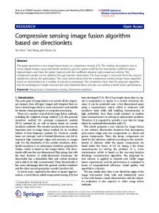
Fig u re 6. (a) Black and white print of an RGB TM/SIR-B false color composite with TM bands 4 (red) and 3 (green) and SIR-B (blue). The high speckle noise of the SIR-B data makes the location of cartographic features extremely difficult. (b) Black and white print of an IHS display of the merged TM/SIR-B dataset with TM bands 4 (intensity) and 3 (hue) and SIR-B (saturation). The IHS display provides better discrimination and is relatively noise free.
156
principal component or decorrelation stretch transforms to the image layers (Niblack, 1986); and (c) make use of the intensity-hue-saturation (IHS) color transform (Haydn 1982). Of these approaches, the IHS transform appears most useful for efficient integration of very dissimilar images (Koger, 1984). Noisy or low resolution et al"
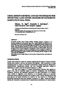
image layers such as SAR or thermal infrared images, can be assigned to the saturation component, whereas high resolution/high SNR data can modulate the intensity and hue components, respectively (figure 6b). To assess the merits of the multisensor TM/SIR-8 dataset, cartographic features were digitized from single image and IHS enhanced image layers and compared to corresponding features on U.S. Geological Survey (USGS) 1:24,000; 1:100,000; and 1 :250,000 scale topographic maps. Features shown on these maps were grouped into linear, areal and point features, and then manually digitized to establish reference values for completeness by category at each map scale. The ratio of feature information extracted from the satellite data to the reference values for the maps determined the percent completeness values (Welch and Ehlers, 1988). Approximately 40 to 70 percent of the planimetric information depicted on maps of 1 :24,000 to 1 :250,000 scale could be extracted from the SIR-8 data, whereas 55 to 85 percent completeness values could be obtained from the TM image. These values, however, could be increased to about 65 to 95 percent completeness for the IHS enhanced TM/SIR-8 multisensor dataset (figure 7). The potential for using IHS fused TM/SIR-8 images for map compilation and revision even at a scale of 1:24,000 is illustrated in figure 8. PERCENT COMPLETENESS
100
Fig U re 7. Percent completeness of map detail as a function of map scale for the TM, SIR-8 and IHS 1 : 24,000
1 : 100,000
I : 250,000
merged TM/SIR-8 datasets.
~Il!~j@~
SIR-B
~TM
TM/SIR-B
IMAGE SHARPENING A very direct approach to image enhancement is the use of high resolution data, e.g. SPOT HRV 10-m panchromatic images, to sharpen images of lower spatial resolution, e.g. TM or SPOT HRV multispectral data. Once a set of multisensor images is
1
placed in register with a high resolution reference image, the digital numbers (ONs) of the various multispectral bands may be merged with those for the single band (panchromatic) reference image using techniques previously described by Cliche et al. (1985) or Chavez (1986). These methods may be summarized in the following equations: (2) (3)
where ON i and DNj' are the DNs for the ith band of the original and fused multispectral image, respectively; DN(h) is the DN for the high resolution reference image;