Multiple-Precision Fixed-Point Vector Multiply-Accumulator using Shared Segmentation Dimitri Tan1, Albert Danysh2, Michael Liebelt3 Motorola Inc.1,2, University of Adelaide, Australia1,3
[email protected],
[email protected],
[email protected]
I. INTRODUCTION The addition of vector capabilites to a processor architecture can provide a significant boost in performance for multimedia type applications [1]. However, the addition of vector capabilities is typically expensive in terms of area. This paper presents a 64-bit fixed-point vector multiplyaccumulator (MAC) architecture capable of supporting multiple precisions using essentially the same hardware as a 64-bit scalar MAC with only a small increase in delay. The vector MAC can perform one 64x64, two 32x32, four 16x16 or eight 8x8 signed/unsigned multiply-accumulates. The multiplier is based on a radix-4 Booth encoder and a Wallace carry-save adder (CSA) reduction tree. The final 128-bit carry propagate adder is a modified carry-lookahead (CLA) adder. The scalar MAC architecture is “vectorized” by inserting mode-dependent multiplexing into the partial product generation and by inserting mode-dependent kills in the carry chain of the reduction tree and the final carry-propagate adder. This is an example of "shared segmentation" in which the existing scalar structure is segmented and then shared between vector modes. This method can also be applied to other arithmetic algorithms. The remainder of this paper is organized as follows. First the basic architecture of the 64-bit vector MAC is presented. Then the details of each part of the scalar 64-bit MAC are presented along with the required modifications
necessary to support the vector functionality. Next some existing alternative implementations are discussed for the purposes of comparison. Following that, a VLSI implementation of the vector MAC is presented with a delay and area comparison against the scalar version of the MAC.
II. MULTIPLY-ACCUMULATE TECTURE
(MAC) ARCHI-
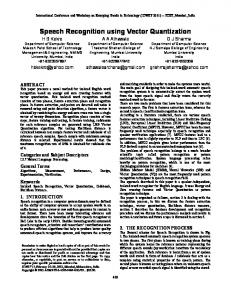
II.I. Overview The block diagram of the vector MAC unit is shown in Fig. 1. The vector MAC unit consists of a modified Booth [2] recoder partial product generator, a Wallace [4] carrysave adder (CSA) reduction tree and a final carry-propagate adder (CPA). The CPA is implemented using a carry-lookhead adder (CLA) consisting of 4-bit carry-lookahead blocks. The accumulator is fed into the Wallace tree and only adds one extra stage of CSA delay. This is a fairly typical MAC design. The mode[3:0] control signals determine which of the vector modes the MAC is to operate in. The unsigned control signal selects unsigned multiplication. The details of the implementation which facilitate the vector functionality will be covered in the proceeding sections. mode[3:0] unsigned
Abstract This paper presents a 64-bit fixed-point vector multiply-accumulator (MAC) architecture capable of supporting multiple precisions. The vector MAC can perform one 64x64, two 32x32, four 16x16 or eight 8x8 bit signed/unsigned multiply-accumulates using essentially the same hardware as a scalar 64-bit MAC and with only a small increase in delay. The scalar MAC architecture is “vectorized” by inserting mode-dependent multiplexing into the partial product generation and by inserting mode-dependent kills in the carry chain of the reduction tree and the final carry-propagate adder. This is an example of "shared segmentation" in which the existing scalar structure is segmented and then shared between vector modes. The vector MAC is area efficient and can be fully pipelined which makes it suitable for high-performance processors and possibly dynamically reconfigurable processors.
accumulator (C) multiplicand (A)
multiplier (B)
Partial Product Generator (PPG)
Partial Product Reduction Tree (PPRT)
Final Carry-Propagate Adder (CPA)
result (R)
Fig. 1.
Multiply-Accumulate (MAC) Architecture Block Diagram
II.II. Scalar Partial Product Generator (PPG) The Scalar Partial Product Generator (PPG) uses radix4 Booth recoding which reduces the number of partial products from n to (n/2+1) for an n x n bit multiplication. The extra partial product is for handling signed/unsigned
multiplication and is generated when the multiplier is sign extended. The partial products use sign encoding instead of sign extension for handling the negatively weighted most significant bit [3],[6]. This avoids having to sign extend the partial products to the full width of the 128-bit result. The radix-4 Booth algorithm encodes groups of three multiplier bits overlapping by one bit into five possibilities - selze (“zero”), selp1 (“+1”), selp2 (“+2)”, seln1 (“-1”) and seln2 (“-2). As mentioned previously, the last partial product is used to handle signed and unsigned numbers. Note that each partial product is appended with two bits, one of which may be a “1” if the previous partial product is being twoscomplemented. Hence these extra two bits are the seln2 and seln1 Booth selects from the previous partial product and are known as “hot ones” [3].
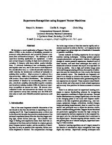
II.III. Vector Partial Product Generator (VPPG) The block diagram for the Vector PPG is shown in Fig. 2 and is identical to a scalar PPG except for some additional multiplexing of the multiplicand and some masking applied to the multiplier. A[63:0]
vector1 8x8 vector2 8x8
0's
vector3 8x8 vector4 8x8
vector5 8x8
0's
vector6 8x8 vector7 8x8
Fig. 3. Simplified Vector Booth Partial Product Array for 64x64 bit multiplication in 8 bit-mode
vector0 16 x 16
B[63:0] 0's vector1 16 x 16
* Vector Masking (zero insert) * Vector Sign Extension
* Vector Masking and Muxing * Vector Sign Extension * Vector Sign Encoding * Vector Twos Complement Increment
Extra logic to support vector modes
vector2 16 x 16
"vectorized" multiplier
(unbuffered)
"vectorized" multiplicand
vector0 8x8
Multiplier
unsigned mode[3:0]
Multiplicand
subgroup has been truncated by one bit since it overlaps by one bit with the first partial product of the next subgroup. Furthermore, take special note of the last partial product which is used to support unsigned mode for all vector elements instead of having an extra partial product for each vector element.
seln1[32:0] seln2[32:0] ("hot ones")
Booth Muxes (buffered)
Radix-4 Booth Recoder Booth Mux Selects selze[32:0] selp1[32:0] seln1[32:0] selp2[32:0] seln2[32:0]
0's vector3 16 x 16
Fig. 4. Simplified Vector Booth Partial Product Array for 64x64 bit multiplication in 16 bit-mode
vector0 8x8 vector1 8x8
PP0[68:0] Partial Products
vector2 8x8
0's
vector3 8x8
PP32[68:0]
Fig. 2.
vector4 8x8
Vectorized Partial Product Generator Block Diagram
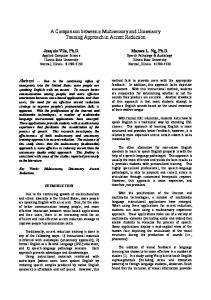
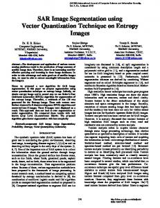
The Vector Partial Product Generator (VPPG) must be able to generate the correct partial products for each of the supported vector modes. Each of the vector modes has a corresponding array of partial products. Each of these arrays of partial products can be overlayed on top of the array of partial products required for the 64-bit scalar mode as shown in Fig. 3, Fig. 4 and Fig. 5. A more detailed example of the partial product array for the 8x8 vector mode is shown in Fig. 6. In this example, each subgroup of partial products corresponds to an 8x8 bit vector element multiplication. Note that the fourth partial product of each
vector5 8x8
0's
vector6 8x8 vector7 8x8
Fig. 5. Simplified Vector Booth Partial Product Array for 64x64 bit multiplication in 32 bit-mode
We will next examine what needs to be done to enable these partial product arrays to be merged. First we will consider changes to the multiplier (B) operand path through the Booth recoder and then the multiplicand (A) operand path through the Booth muxes.
0 0
B[63:0]
B[47:32]
vector 2
vector 1
S0 S0
64-bit mode
S1 S1
32-bit mode
B[63:48] S3 S3
16-bit mode
vector 7
vector 3
S2 S2
S S 0 B[63:56] S S
B[63:32]
0
vector 5
B[47:40]
S0 S0
S2 S2
0
vector 3
vector 1
B[31:16]
B[31:0]
vector 0
0 S0 S0
S S 0 B[31:24] S S 0
B[39:32]
vector 4
S S 0 B[55:48]
vector 6
S S
Fig. 7.
0
0 vector 0 vector 1
B[15:8]
S S 0 B[23:16]
vector 2
S S 0
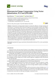
II.IV.I. Vector Booth Recoder In the vector MAC, the Booth recoder is the same as that used for the scalar MAC except that the multiplier operand (B) input changes depending on the vector mode. This is illustrated in Fig. 7 which shows the Booth recoder multiplier input for each vector mode. In the scalar PPG, the first partial product is generated by assuming B[-1] = 0. In the vector Booth Recoder, this “0” must be inserted at vector element boundaries for the first partial product of each subgroup. These are the extra “0” bits in Fig. 7. For example, in the 8-bit vector mode, the fifth partial product uses bit triplet {B[9],B[8],”0”} instead of {B[9],B[8],B[7]} as used in the scalar PPG. The
8-bit mode
h2 h1
vector 6
LEGEND pp = Partial Product h2 = Additional +1 for 2's complement if selecting negative1 for previous partial product (i.e. "hot one") h1 = Additional +1 for 2's complement if selecting negative2 for previous partial product (i.e. "hot one") n = Value of negatively weighted sign bit and p = ~n
p n 1 n p vector 7 1 p vector 7 h2 h1 1 p vector 7 h2 h1 p vector 7 h2 h1 vector 7 h2 h1
p
1 p
p n n vector 6 1 p vector 6 h2 h1 vector 6 h2 h1 vector 6 h2 h1
95 103 111 119 127
pp 0 pp 1 pp 2 pp 3 pp 4 pp 5 pp 6 pp 7 pp 8 pp 9 pp 10 pp 11 pp 12 pp 13 pp 14 pp 15 pp 16 pp 17 pp 18 pp 19 pp 20 pp 21 pp 22 pp 23 pp 24 pp 25 pp 26 pp 27 pp 28 pp 29 pp 30 pp 31 pp 32
Fig. 6. Vector Booth Partial Product Array for 64x64-bit multiplication in 8-bit vector mode.
B[15:0]
B[7:0] 0
vector 0
0
Note 2: pnn and 1p prepends are sign ecoding to avoid sign extension
Note 1: Last PP does not need hot ones since it is always 0, pos1 or pos2 since prepend 0 to form last PP bit group
vector 1
h2 h1
vector 1 p n n h2 h1 vector 1 1 p h2 h1 vector 1 h2 h1 vector 1 p
31
1 p
23
15
vector 0
h2 h1
7 0 p n n vector 0 1 p vector 0 h2 h1 h2 h1 1 p vector 0 h2 h1 p vector 0
pp 0 pp 1 pp 2 pp 3 pp 4 pp 5 pp 6 pp 7 pp 8 pp 9 pp 10 pp 11 pp 12 pp 13 pp 14 pp 15 pp 16 pp 17 pp 18 pp 19 pp 20 pp 21 pp 22 pp 23 pp 24 pp 25 pp 26 pp 27 pp 28 pp 29 pp 30 pp 31 pp 32
zero insertion is implemented by masking the multiplier operand bits with a signal that is a function of the mode and bit position. Hence an extra two-input nand gate is added to the critical path.
Vector Booth Recoder Inputs
To support unsigned numbers, the scalar PPG generates an additional partial product since the multiplier operand is extended by two bits to form the bit triplet. Similarly, each vector element of the multiplier operand B must be extended by two bits. This is indicated in Fig. 7 by the additional “sign” bits that are denoted by si where i is the vector element index. Hence the vector Booth PPG must generate an additional partial product for every vector element. The sign bits are different for each vector element and are formed according to equation (1). si = MSB . ~unsigned
(1)
where MSB is the most significant bit of the vector element i.
The sign bits are used to generate the extra partial product for each vector element which are then combined into a single partial product that is twice the width of the operands i.e. 128-bits. This combination can be done because
the extra partial products for each vector element do not overlap. They do however cross the vector element boundaries and need to be truncated by 3 bits i.e. the sign encoding bits are truncated at the MSB end. Note that the Booth select for the last partial product is either selze (“select zero”) or selp1 (“select plus one”) and therefore does not need the “hot ones” bits. II.V.II. Vector Booth Muxes The MSB of each partial product generated by the PPG is negatively weighted. Consequently, the partial products must be either sign extended out to the full width of the result or sign encoded as mentioned earlier. In sign encoding, the negatively weighted MSB is replaced by {p,n,n} for the first partial product or {1,p} for the remaining partial products where n is the MSB or sign-bit of the multiplicand operand and p=~n [6]. In the Vector PPG, the sign encoding must be performed at each vector element boundary using the appropriate sign-bit for that vector element. The sign-bit is dependent on the vector mode, the vector element in question and whether signed or unsigned mode is selected. The final complication in the Vector PPG involves handling the two’s complement of the multiplicand when one the Booth selects seln1 (“select -1”) or seln2 (“select -2”) are asserted. The two’s complement requires inverting the multiplicand and then adding one to the LSB. To avoid adding extra partial products for the sole purpose of performing the increment, the extra ones are simply appended to the next partial product. Thus the extra bits appended are {seln2,seln1} for the previous partial product. This is a standard practice [3]. However, in the vector PPG, these extra “hot one” bits must be inserted at vector element boundaries which vary depending on the mode. It appears that each vector mode has a unique set of partial products. The naive or non-optimal approach to merging these partial products would be to form the partial products for each mode and select the correct partial product based on the vector mode as shown in Fig. 8. This requires an additional five 64-bit 4:1 multiplexers for each partial product. The Booth recoder is usually the critical path so adding the extra 4:1 mux delay prior to the Booth muxes does not add to the critical path except for the appending of the “hot one” bits {seln2,seln1}. These bits are the Booth selects for the previous partial product. The naive approach can be improved by observing that at most bit positions there are less than four unique data to select from. Infact, at some bit positions there is no additional logic required at all compared to the scalar Booth PPG. This is illustrated in Fig. 9 which shows a selection of partial products and how they overlap for each mode. In the worst case a 4-input mux is required, such as for the sign encoding bits in partial product 30. The remaining bits
require either a 3-input mux, a 2-input mux, a 2-input “and” gate or no extra logic at all depending on significance. The mux selects are a function of the mode control signals, significance and partial product number. Similarly, one input to the “and” gate is a function of the mode control signals, significance and partial product number. This “and” gate input simply masks the other input which is the multiplicand. The 2-input and 3-input mux inputs are either tied to ground, the multiplicand, the sign encoding bits, or the seln1 and seln2 Booth selects for the previous partial products. A more detailed example of the partial product overlap is given in Fig. 10. mode[3:0]
Multiplicand
unsigned
Sign Encoding
Sign Extend
Booth selects {seln2,seln1} from previous PP ("hot ones")
Invert, shift, zero
0's 0's 0's
0's 0's 0's Intermediate partial products 0
1
4:1
2
3
Vector Mode Muxes
Booth Mux
0
0
1
2 5:1
3
4
1
4:1
2
3
mode[3:0] 0: 8-bit mode 1: 16-bit mode 2: 32-bit mode 3: 64-bit mode
0: selze i.e. "select 0" 1: selp1 i.e. "select +a" 2: selp2 i.e. "select +2a" 3: seln1 i.e. "select -a" 4: seln2 i.e. "select-2a"
Partial Product i
Fig. 8.
Naive Vector Partial Product Generation
Note that the last partial product cannot be generated this way and requires full multiplexing as in Fig. 8. This is because the Booth selects for the last partial product are different for each vector element and each mode. The last partial product is also the full width of the result (128 bits) and thus enters the Wallace tree in one of the last two stages. The theoretical critical path is from the multiplier B, through the vector masking, the Booth Recoder, the vectormode muxes and finally the booth mux. The extra 2-input “nand” gate used for the masking of the multiplier occurs in parallel with part of the Booth recoder logic and therefore does not add delay to the critical path. It is assumed the mask is precalculated to avoid adding to the critical path. The vector mode muxing is designed to allow for the late “seln1” or “seln2” Booth select and inserts the delay of a 2-input mux. The delay of the 2-input mux will occur in parallel to the significant buffering of the Booth selects
before they reach the Booth muxes. Assuming these delays are about equal the extra logic does not add an significant delay to the theoretical critical path. The real critical path is of course dependent on the technology and the implementation details.
Fig. 9. Example of partial product overlap between vector modes
1 11 11 11 2 21 11 00 99 88 87 77 66 55 44 43 33 22 11 7 09 21 42 65 87 09 21 43 65 87 09 21 43 65 87 0 Partial Product 1 8-bit mode ...................................................................................................................eeexxxxxxxxhh 16-bit mode ...........................................................................................................eeexxxxxxxxxxxxxxxxhh 32-bit mode ...........................................................................................eeexxxxxxxxxxxxxxxxxxxxxxxxxxxxxxxxhh 64-bit mode ...........................................................eeexxxxxxxxxxxxxxxxxxxxxxxxxxxxxxxxxxxxxxxxxxxxxxxxxxxxxxxxxxxxxxxxhh Partial Product 9 8-bit mode ...................................................................................eeexxxxxxxxhh................................ 16-bit mode ...........................................................................eeexxxxxxxxxxxxxxxxhh................................ 32-bit mode ...........................................................................eeexxxxxxxxxxxxxxxxxxxxxxxxxxxxxxxxhh................ 64-bit mode ...........................................eeexxxxxxxxxxxxxxxxxxxxxxxxxxxxxxxxxxxxxxxxxxxxxxxxxxxxxxxxxxxxxxxxhh................ Partial Product 26 8-bit mode .................eeexxxxxxxxhh.................................................................................................. 16-bit mode .........eeexxxxxxxxxxxxxxxxhh.................................................................................................. 32-bit mode .........eeexxxxxxxxxxxxxxxxxxxxxxxxxxxxxxxxhh.................................................................................. 64-bit mode .........eeexxxxxxxxxxxxxxxxxxxxxxxxxxxxxxxxxxxxxxxxxxxxxxxxxxxxxxxxxxxxxxxxhh.................................................. Partial Product 30 8-bit mode .eeexxxxxxxxhh.................................................................................................................. 16-bit mode .eeexxxxxxxxxxxxxxxxhh.......................................................................................................... 32-bit mode .eeexxxxxxxxxxxxxxxxxxxxxxxxxxxxxxxxhh.......................................................................................... 64-bit mode .eeexxxxxxxxxxxxxxxxxxxxxxxxxxxxxxxxxxxxxxxxxxxxxxxxxxxxxxxxxxxxxxxxhh.......................................................... LEGEND h = two's complement increment bits i.e. "hot ones" i.e. Booth selects {seln2,seln1}
x = multiplicand bit
e = sign encoding - 3 bits since {1,p} and possibly shifted by 1 bit
. = zero
Fig. 10. Example of Partial Product 1 assuming Booth select “selp2” (“select positive two”) asserted
II.VI. Scalar Partial Product Reduction Tree (PPRT)
The Scalar Partial Product Reduction Tree (PPRT) reduces the set of partial products down to two for the final carry-propagate addition. A Wallace CSA Tree consisting of 3:2 compressors or full-adders (FAs) is used to implement the scalar PPRT [4]. The accumulator is also added
63
55
47
39
31
23
15
PP1 in 8–bit mode PP1 in 16–bit mode 1
PP1 in 64–bit mode
1
P a63 a62 a61
Logic required
P
a33 a32
and2
mux3
PP1
and2
a7
a6
a5
a4
a3
a2
a1
a0
0
h2
h1
a15 a14 a13 a12 a11 a10
a9
a8
a7 a6
a5
a4
a3
a2
a1
a0
0
h2
h1
a17 a16 a15 a14 a13 a12 a11 a10
a9
a8
a7 a6
a5
a4
a3
a2
a1
a0
0
h2
h1
a17 a16 a15 a14 a13 a12 a11 a10
a9
a8
a7 a6
a5
a4
a3
a2
a1
a0
0
h2
h1
mux3
mux2
a7 a6
a5
a4
a3
a2
a1
a0
0
P
a15 a14 a13 a12 a11 a10
LEGEND PP = Partial Product 1
P
= Sign encoding. This is different for every mode and may also be in different bit positions.
h2
h1
= Two's complement increment from previous partial product. ("hot ones"). This is the same for every mode but may be in different bit positions.
ai
= Multiplicand bit of significance "i" where i = 0 to 63
0
P
1
PP1 in 32–bit mode
7 1
into the Wallace tree to avoid an extra carry-propagate addition. The number of 3:2 levels in the Wallace tree is given by equation . Levels = ( log N ) ⁄ ( log 1.5 )
(2)
where N = total number of partial products
For the MAC the number of partial products is 64 ⁄ 2 + 1 + 1 = 34 . One of the two additional partial products is for supporting signed/unsigned numbers and the other is the accumulator. Hence the Wallace tree has log 〈 34〉 ⁄ log ( 1.5 ) = 8.7 = 9 levels . The total number of full adders required is 3088.
II.VII. Vector Partial Product Reduction Tree (PPRT) There are two methods for vectorizing the scalar PPRT. The first method observes that the 16-bit vector mode reduction trees can be created from the 8-bit vector mode reduction trees with the two’s complement partial product and accumulator excluded. An additional 4:2 stage is used to reduce these partial products and produce the result for each of the 8-bit vector elements. The vector result for the 8-bit mode is formed by concatenating the vector element results. This is then applied recursively until the reduction tree for the 64-bit mode is created. The vector results for each mode must then be multiplexed together to form the final two partial products. The first method is illustrated in Fig. 11. Note for each mode only one branch of the vector reduction tree is shown fully.
The second method involves killing the carries which cross the vector element boundaries at every level of the CSA tree. The bit positions of the vector boundaries depend on the vector mode. The second method could be applied equally well to a Wallace tree or a Dadda [5] tree and will be elaborated below. The killing of carries in the second method can be achieved by inserting a 2-input “and” gate at each vector element boundary to mask the carry-in input of each corresponding full-adder. Since a CSA does not have a carry-propagate path, the carry-kill “and” gate can be incorporated into the full-adder design such that it does not add any additional delay through the CSA tree as shown in equation (3). sum = ( a ⊕ b ) ⊕ ( c in ⋅ ¬kill ) c out = ( a ⋅ b ) + [ ( a + b ) ⋅ ( c in ⋅ ¬kill ) ]
A possible realization of the full-adder is illustrated in equation Fig. 12. which clearly shows that the addition of the kill signal will not significantly increase delay since the extra gate is in parallel with other terms. a b sum cin kill
a b a
pp11 pp10 pp9 pp8
pp7 pp6 pp5 pp4
pp3 pp2 pp1 pp0
4:2
4:2
4:2
4:2
4:2
4:2
pp_32_0 acc_32_0
4:2
4:2
pp_32_0 acc_32_0
of CSA tree 4:2
4:2
8-bit mode Final PP pair Element 0
4:2
16-bit mode Final PP pair Element 0
4:2
32-bit mode Final PP pair Element 0
64-bit mode Final PP pair
LEGEND: pp_i_j = Two's complement PP for mode i vector element j
0: 8-bit mode 3 2 1 0
1: 16-bit-mode
4:1
2: 32-bit mode 3: 64-bit mode
acc_i_j = Acumulator for mode i
cout oai21
kill
pp_16_0 acc_16_0
4:2 From other half
cin
pp_8_0 acc_8_0
pp15 pp14 pp13 pp12
b
4:2
(3)
vector element j Final PPs
Fig. 11. Vector Partial Product Reduction Tree - Method 1
Fig. 12. Full-adder with carry-in kill for Vector PPRT - Method 2
The second method was chosen for the vector MAC because it does not add delay to the critical path and does not require much extra hardware. The first method adds a 4-input mux to the critical path and requires several extra rows of CSAs.
II.VIII. Scalar Final Carry Propagate Adder (CPA) The final CPA sums the two remaining partial products generated by the Wallace Tree. The scalar MAC uses a standard 128-bit carry-lookahead (CLA) adder comprised of 4-bit CLA blocks. This adder was chosen because it is a fast adder and can easily be modified to create a vector adder. It should be noted that CLA adders comprised of 4bit CLA blocks are most efficient for data widths that are powers of 4. Thus there are probably better choices for a fast 128-bit adder. For the purposes of this paper this can be overlooked.
II.IX. Vector Final carry Propagate Adder (CPA) There are essentially two methods for vectorizing the final CPA. The first method involves extending the width of the adder by one bit at every potential vector element boundary and conditionally inserting zeros in order to kill the carries. Hence this requires that the adder is extended by the number of vector elements supported by the lowest granularity vector mode. In the case of the 64-bit vector MAC we require an extra 8 bits since for 8-bit mode there are 8 vector elements. The total width of the adder would thus be 136 bits. For each extra significance, there is a pair of inputs. Both inputs are set to zero if a carry kill is required. Alternatively, one of the inputs is set to a one and the other to zero if a carry propagate (no carry kill) is required. The extra bits are then dropped when forming the final result. The second method involves killing the carries which cross the vector element boundaries that are determined by the vector mode selected. This is the same method used in the Vector Wallace tree. The extra 2-input “and” gate can be combined into the 4-bit CLA blocks without adding additional delay to the critical path. The 4-bit CLA equations with the carry-in kill term are given in equation (4). cout 0 = g 0 + c in ⋅ p 0 ⋅ ( ¬kill )
(4)
cout 1 = g 1 + g 0 ⋅ p 1 + c in ⋅ p 0 ⋅ p 1 ⋅ ( ¬kill ) cout 2 = g 2 + g 1 ⋅ p 2 + g 0 ⋅ p 1 ⋅ p 2 + c in ⋅ p 0 ⋅ p 1 ⋅ p 2 ⋅ ( ¬kill ) 0
g3 = g3 + g2 ⋅ p3 + g1 ⋅ p2 ⋅ p3 + g0 ⋅ p1 ⋅ p2 ⋅ p3 0
p3 = p0 ⋅ p1 ⋅ p2 ⋅ p3 0
where g 3 is the block generate from bit 0 to bit 3 0
and p 3 is the block propagate from bit 0 to bit 3
In the scalar 4-bit CLA block, the critical path is from the carry-in cin and the group generate inputs since the group propagates are available much earlier. Therefore the cin and the group generate inputs are typically placed close to the output in the circuit topology. This means that there is less capacitance to discharge when the critical signals finally change. In the vector CLA block the extra kill term is also available early. Consequently, it does not add additional capacitance to discharge provided the critical inputs remain closest to the output. The vector MAC was implemented using the second method since it does not add extra delay to the critical path.
III. EXISTING IMPLEMENTATION SCHEMES There are essentially two existing schemes for implementing a vector multiply-accumulator [6], [7], [8], [9], [10], [11], [12], [13]. The first scheme involves having separate hardware for each vector element of each mode and
then muxing the result at the end. Hence to achieve the equivalent of the MAC presented in this paper, the first scheme requires one 64-bit MAC, two 32-bit MACs, four 16-bit MACs and eight 8-bit MACs. This is a brute force scheme and wastes a great deal of area. In addition, the delay of the final 4:1 result mux is inserted into the critical path. Such a design can be fully-pipelined without causing pipeline stalls. The second scheme involves building wider vector elements out of several of the narrower vector elements and then adding the multiple results together. This can be done consecutively or by recirculating the data back through the unit over more than one cycle. For instance, a 2Nx2N multiplier can be built out of four NxN multipliers by generating four 2N products which can then be added to form the 4N product. This scheme is not suited to supporting more than two vector modes. Furthermore, if the data is recirculated back through the MAC unit, then the pipeline feeding the MAC must stall. This is unsuitable for high performance processors since it complicates the instruction scheduling. Typically a vector MAC will use a combination of the above schemes.
IV. IMPLEMENTATION The vector MAC presented in this paper was implemented in Verilog HDL at a structural level and then synthesized, placed and routed in a 0.13 um bulk-silicon technology. Synopsys Physical Compiler was used for synthesis and initial placement. Cadence QPlace/Warp was used for final placement and routing. A “SPICE-accurate” in-house static timing tool was used to determine propagation delays. In addition, the scalar MAC design was also implemented for direct comparison. The results are shown in Table 1 for both MAC designs with no pipeline registers. There was a 8% increase in delay and a 2% increase in area over the scalar 64-bit MAC. TABLE 1. IMPLEMENTATION SUMMARY Design
Delay (ps)
Area (µm2)
Scalar MAC
2282.45
187 553
Vector MAC
2470.44
191 301
The vector MAC was tested by cycling through all possible combinations of inputs in which the two most-significant bits and two least significant-bits for each vector element were varied while the intermediate bits were all ones or all zeros. In addition, some random pattern generation was used.
V. CONCLUSIONS In this paper, we presented the design and implementation of a vector multiplier-accumulate (MAC) unit that can perform one 64x64, two 32x32 bit, four 16x16 or eight 8x8 signed/unsigned multiply-accumulates using essentially the hardware as a 64-bit multiplier-accumulator and without significantly more delay. The concept of "shared segmentation" is introduced in which the existing scalar hardware structure is segmented and then shared between vector modes. In the case of the MAC, the scalar architecture is “vectorized” by inserting mode-dependent masking into the partial product generation and by inserting modedependent kills in the carry chain of the reduction tree and final carry-propagate adder. The "shared segmentation" concept can be applied to other arithmetic units such as floating-point addition or multiplication.
FUTURE WORK We are in the process of designing and implementing other vector arithmetic units by applying the "shared segmentation" concept with particular focus on floating-point addition and multiplication. We are also evaluating different interconnection strategies in which an array of such “vectorized” execution units are connected together to form a powerful execution engine suitable for computationally intensive applications such as multimedia and digital signal processing.
REFERENCES [1] Lee, C.G.; Stoodley, M.G. “Simple vector microprocessors for multimedia applications” Microarch., 1998. MICRO-31. Proc. 31st Annual ACM/IEEE Int. Symp. on , pp. 25-36, 1998. [2] Booth, “A Signed Binary Multiplication Algorithm”, Qt. J. Mech. Appl. Math., vol. 4, pp. 236-240, 1951. [3] S. Vassiliadis; E.M. Schwarz; B.M. Sung, “Hardwired multipliers with encoded partial products”, IEEE Trans. on Computers, Vol. 40, Issue 11 , Nov 1991, pp. 1181 -1197. [4] C.S.Wallace, “A suggestion for a fast multiplier”, IEEE Trans. Electron. Comput., vol. EC-13, pp. 1417, 1964. [5] L. Dadda, “Some Schemes For Parallel Multipliers”, Alta Freq., 34, pp. 349-356, 1965. [6] Behrooz Parhami, “Computer Arithmetic - Algorithms and Hardware Designs”, pp. 178-180, 191-195, ISBN 0-19-512583-5, 2000. [7] M.S. Schmookler et al, “A Low-power, High-speed Implementation of a PowerPC Microprocessor Vector Extension’, Comp. Arith., 1999. Proc. 14th IEEE Symp., 1999.
[8] A.A. Farooqui; V.G. Oklobdzija, “General Data-Path Organization of a MAC unit for VLSI Implementation of DSP Processors”, Circ. & Sys., ISCAS ’98. Proc. IEEE Int. Symp., Vol. 2, pp. 260 -263, 1998. [9] W.F. Wong; E. Goto, “Division and Square-Rooting using a split multiplier”, Electr. Letters, Vol. 28 No. 18, pp. 1758-1759, Aug 1992. [10] Y. Liao; D.B. Roberts ,“A High-Performance and Low-Power 32-bit Multiply-Accumulate Unit with Single-Instruction-Multiple-Data (SIMD) Feature”, IEEE J. of Solid-State Cir., Vol. 37, No. 7, July 2002. [11] R.B. Lee, “Multimedia Extensions for General-Purpose Processors”, Sig. Proc. Sys., SIPS 97, Nov 1997, pp. 9 -23. [12] Tang, K.C.; Wu, A.K.M.; Fong, A.S.; Pao, D.C.W., “Integrated partition integer execution unit for multimedia and conventional applications“, IEEE Int. Conf. on Electr., Circ. and Sys., 1998, Vol. 2, pp. 103 -107. [13] Rong Lin, “Trading bitwidth for array size: a unified reconfigurable arithmetic processor design”, Int. Symp. on Qality Elec. Design, 2001, pp. 325-330.