governor of turbogenerators on multimachine power systems. The neurocontroller ... stationary, fast acting, multi-input-multi-output (MIMO) device with a wide ...
IEEE TRANSACTIONS ON NEURAL NETWORKS, VOL. 14, NO. 5, SEPTEMBER 2003
1047
Implementation of Adaptive Critic-Based Neurocontrollers for Turbogenerators in a Multimachine Power System Ganesh Kumar Venayagamoorthy, Senior Member, IEEE, Ronald G. Harley, Fellow, IEEE, and Donald C. Wunsch, Senior Member, IEEE
Abstract—This paper presents the design and practical hardware implementation of optimal neurocontrollers that replace the conventional automatic voltage regulator (AVR) and the turbine governor of turbogenerators on multimachine power systems. The neurocontroller design uses a powerful technique of the adaptive critic design (ACD) family called dual heuristic programming (DHP). The DHP neurocontrollers’ training and testing are implemented on the Innovative Integration M67 card consisting of the TMS320C6701 processor. The measured results show that the DHP neurocontrollers are robust and their performance does not degrade unlike the conventional controllers even when a power system stabilizer (PSS) is included, for changes in system operating conditions and configurations. This paper also shows that it is possible to design and implement optimal neurocontrollers for multiple turbogenerators in real time, without having to do continually online training of the neural networks, thus avoiding risks of instability. Index Terms—Adaptive critics, hardware implementations, multimachine power system, neural networks, neurocontrol, optimal turbogenerator control.
I. INTRODUCTION
P
OWER-SYSTEM control essentially requires a continuous balance between electrical power generation and a varying load demand, while maintaining system frequency, voltage levels, and power grid security. However, generator and grid disturbances can vary between minor and large imbalances in mechanical and electrical generated power, while the characteristics of a power system change significantly between heavy and light loading conditions, with varying numbers of generator units and transmission lines in operation at different times. The result is a highly complex and nonlinear dynamic electric power grid with many operational levels made up of a wide range of energy sources with many interaction points. As the demand for electric power grows closer to the available sources, the complex systems that ensure the stability and security of the power grid are pushed closer to their edge. Manuscript received September 15, 2002. This work was supported by the National Research Foundation of South Africa and by the National Science Foundation. G. K. Venayagamoorthy and D. C. Wunsch are with the Department of Electrical and Computer Engineering, University of Missouri-Rolla, Rolla, MO 65409 USA. R. G. Harley is with the School of Electrical and Computer Engineering, Georgia Institute of Technology, Atlanta, GA 30332-0250 USA and also with the School of Electrical and Electronic Engineering, University of Natal, Durban, Durban 4041, South Africa. Digital Object Identifier 10.1109/TNN.2003.816054
Synchronous turbogenerators supply most of the electrical energy produced by mankind, and are largely responsible for maintaining the stability and the security of the electrical network. The effective control of these devices, is therefore, very important. However, a turbogenerator is a highly nonlinear, nonstationary, fast acting, multi-input-multi-output (MIMO) device with a wide range of operating conditions and dynamic characteristics that depend on the power system to which the generator is connected too. Conventional automatic voltage regulators (AVRs) and turbine governors are designed based on some linearized power system model, to control the turbogenerator in some optimal fashion around one operating point. At any other operating points the conventional controller technology cannot cope well and the generator performance degrades, thus driving the power system into undesirable operating states [1]. Additionally, the tuning and integration of the large number of control loops typically found in a power station can prove to be a costly and time-consuming exercise. In recent years, renewed interest has been shown in power-system control using nonlinear control theory, particularly to improve system transient stability [2]–[6]. Instead of using an approximate linear model, as in the design of the conventional power system stabilizer, nonlinear models are used and nonlinear feedback linearization techniques are employed on the power system models, thereby alleviating the operating point dependent nature of the linear designs. Nonlinear controllers significantly improve the power system’s transient stability. However, nonlinear controllers have a more complicated structure and are difficult to implement relative to linear controllers. In addition, feedback linearization methods require exact system parameters to cancel the inherent system nonlinearities, and this contributes further to the complexity of stability analysis. The design of decentralized linear controllers to enhance the stability of interconnected nonlinear power systems within the whole operating region remains a challenging task [7]. However, the use of computational intelligence, especially artificial intelligence, especially artificial neural networks (ANNs), offers a possibility to overcome the above mentioned challenges and problems of conventional analytic methods. ANNs are good at identifying and controlling nonlinear systems [8], [9]. They are suitable for multivariable applications, where they can easily identify the interactions between the system’s inputs and outputs. It has been shown that a multilayer perceptron (MLP) neural network using deviation signals
1045-9227/03$17.00 © 2003 IEEE
1048
(for example, deviation of terminal voltage from its steady value) as inputs, can identify experimentally the complex and nonlinear dynamics of a multimachine power system, with sufficient accuracy [10], and this information can then be used to design a nonlinear controller which will yield an optimal dynamic system response irrespective of the load and system configurations. Previous publications have reported on the different aspects of neural network based control of generators. Some have proposed the use of neural-network-based power system stabilizers (PSSs) to generate supplementary control signals [11]–[15]. Optimal PSS parameters have been derived using techniques such as Tabu search and genetic algorithms and shown to be effective over a wide range of operating conditions in simulation [16], [17]. Others have considered a radial basis function (RBF) neural network in simulation, using actual values of signals, and not the deviation values of those signals, to replace the AVR [18], and the AVR and the PSS [19]. Another paper [20] has reported on a MLP neural-network regulator replacing the AVR and turbine governor, in simulation only, with deviation signals as inputs and actual signals as outputs of the neural network. Experimental results using the RBF neural-network controller with deviations signals as inputs, and actual signals as outputs of the neural network, to replace the AVR only, have been considered in [21]. References [18], [21] have reported that RBFs have some advantages over the MLP neural networks, with training and locality of approximations, making them an attractive alternative for online applications. Measured results for an MLP-based controller replacing the AVR only, have been reported in [19]. An online trained MLP feedforward neural-network-based controller, with deviations signals [10] as inputs and outputs of the neural network, to replace both the AVR and the turbine governor have been considered in simulation [22] and in real-time implementation on a PC-based platform [23]. However, all these neurocontrollers require continual online training of their neural networks after commissioning. In most of the above results, an ANN is trained to approximate various nonlinear functions in the nonlinear system. The information is then used to adapt an ANN controller. Since an ANN identifier is only an approximation to the underlying nonlinear system, there is always residual error between the true plant and the ANN model of the plant. Stability issues arise when the ANN identifier is continually trained online and simultaneously used to control the system. Furthermore, to update weights of the ANN identifier online, gradient descent algorithms are commonly used. However, it is well known in adaptive control that a brute force correction of controller parameters, based on the gradients of output errors, can result in instability even for some classes of linear systems [24], [25]. Hence, to avoid the possibility of instability during online adaptation, some researchers proposed using ANNs such as radial basis functions, where variable network parameters occur linearly in the network outputs, such that a stable updating rule can be obtained [26]. To date, the development of nonlinear control using ANNs is similar to that of linear adaptive control because the ANNs are used only in linearized regions. Unfortunately, unlike linear adaptive control, where a general controller structure to stabilize a system
IEEE TRANSACTIONS ON NEURAL NETWORKS, VOL. 14, NO. 5, SEPTEMBER 2003
can be obtained with only the knowledge of relative degrees, stabilizing controllers for nonlinear systems are difficult to design. As a result, most research on ANN-based controllers has focused on nonlinear systems, whose stabilizing controllers are readily available once some unknown nonlinear parts are identified, such as (1) with full state feedback, where is to be estimated by an ANN. Even though some methods have been suggested for using ANNs in the context of a general controller structure [27], [28], the stability implication of updating a network online is unknown. Furthermore, since an ANN controller can have many weights, it is questionable whether the network can converge fast enough to achieve good performance. Besides, in closed-loop control systems with relatively short time constants, the computational time required by frequent online training could become the factor that limits the maximum bandwidth of the controller. Previous work by the authors [29] presented a technique using adaptive critics for designing a turbogenerator neurocontroller in simulation on a single machine infinite bus power system, which overcomes the risk of instability [30], the problem of residual error in the system identification [31], input uncertainties [32], and the computational load of online training. This paper extends the work in [29] to the design of multiple adaptive critic’s based neurocontrollers experimentally on a multimachine power system in real time. The design and practical laboratory hardware implementation of nonlinear excitation and turbine neurocontrollers based on dual heuristic programming (DHP) theory (a member of the adaptive critics family) for turbogenerators in a multimachine power system, to replace the conventional automatic voltage regulators (AVRs) and turbine governors, is presented in this paper. The DHP excitation and turbine neurocontrollers are implemented on a digital signal processor (DSP) to control the turbogenerators. The practical implementation results show that both voltage regulation and power system stability enhancement can be achieved with these proposed DHP neurocontrollers, regardless of the changes in the system operating conditions and configurations. These results with the DHP neurocontrollers are better than those obtained with the conventional controllers even with the inclusion of a conventional power system stabilizer. II. ADAPTIVE CRITIC DESIGNS (ACDs) A. Background ACDs are neural-network designs capable of optimization over time under conditions of noise and uncertainty. A family of ACDs was proposed by Werbos [33] as a new optimization technique combining concepts of reinforcement learning and approximate dynamic programming. For a given series of control actions that must be taken sequentially, and not knowing the effect of these actions until the end of the sequence, it is impossible to design an optimal controller using the traditional supervised learning neural network. The adaptive critic method determines optimal control laws for a system by successively
VENAYAGAMOORTHY et al.: IMPLEMENTATION OF ADAPTIVE CRITIC-BASED NEUROCONTROLLERS
adapting two ANNs, namely an action neural network (which dispenses the control signals) and a critic neural network (which “learns” the desired performance index for some function associated with the performance index). These two neural networks approximate the Hamilton–Jacobi–Bellman equation associated with optimal control theory. The adaptation process starts with a nonoptimal, arbitrarily chosen, control by the action network; the critic network then guides the action network toward the optimal solution at each successive adaptation. During the adaptations, neither of the networks need any “information” of an optimal trajectory, only the desired cost needs to be known. Furthermore, this method determines optimal control policy for the entire range of initial conditions and needs no external training, unlike other neurocontrollers. Dynamic programming prescribes a search which tracks backward from the final step, retaining in memory all suboptimal paths from any given point to the finish, until the starting point is reached. The result of this is that the procedure is too computationally expensive for most real problems. In supervised learning, an ANN training algorithm utilizes a desired output and, having compared it to the actual output, generates an error term to allow the network to learn. The backpropagation algorithm is typically used to obtain the necessary derivatives of the error term with respect to the training parameters and/or the inputs of the network. However, backpropagation can be linked to reinforcement learning via the critic network which has certain desirable attributes. The technique of using a critic, removes the learning process one step from the control network (traditionally called the “action network” or “actor” in ACD literature), so the desired complete trajectory over infinite time is not necessary. The critic network learns to approximate the cost-to-go or strategic utility function at each step (the function of Bellman’s equation in dynamic programming) and uses the output of the action network as one of its inputs, directly or indirectly. The cost-to-go function is given as follows:
1049
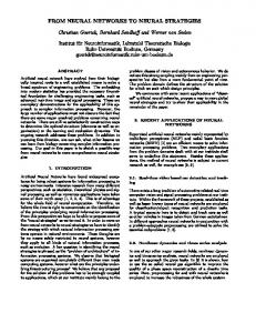
differentiable structure is suitable as a building block. The interrelationships between members of the ACD family have been generalized and explained in detail by Prokhorov [35], [36], whose results have been modified for the study in this paper as shown in Section II-B–D. This paper compares DHP type of critic for neurocontroller implementations, against the results obtained using conventional proportional integral derivative (PID) controllers [37], [38] for multiple turbogenerators. B. Dual Heuristic Programming Neurocontroller The critic neural network in the DHP scheme shown in Fig. 1 estimates the derivatives of with respect to the vector (outputs of the model neural network) and learns minimization of the following error measure over time: (3) where (4) is a vector containing partial derivatives of where . the scalar (.) with respect to the components of the vector The critic neural network’s training is more complicated than in HDP, since there is a need to take into account all relevant pathways of backpropagation as shown in Fig. 1, where the paths of derivatives and adaptation of the critic are depicted by dashed lines. In Fig. 1, the dashed lines mean the first backpropagation and the dashed-dotted lines mean the second backpropagation. The model neural-network in the design of DHP critic and action neural networks are obtained in a similar manner to that described in [10], [29]. In the DHP scheme, application of the chain rule for derivatives yields
(2) is a discount factor for finite horizon problems , is the utility function or the local cost and is an input vector to the critic. Different types of Critics have been proposed. For example, Watkins [34] developed a system known as Q-learning, explicitly based on dynamic programming. Werbos, on the other hand, developed a family of systems for approximating dynamic programming [33]; his approach subsumes other designs for continuous domains. For example, Q-learning becomes a special case of action-dependent heuristic dynamic programming (ADHDP), which is a critic approximating the function (see Section II-B), in Werbos’ family of adaptive critics. A critic which approximates only the derivatives of the function with respect to its states, called the dual heuristic programming (DHP), and a critic approximating both and its derivatives, called the globalized dual heuristic programming (GDHP), complete this ACD family. These systems do not require exclusively neural-network implementations, since any where
(5)
, and , where are the numbers of outputs of the model, action, and critic neural networks, respectively. By exploiting (5), each of components from (4) is determined by of the vector
(6) The signals in Fig. 1 labeled with a path number represent the following. 1) Path 1 represents the outputs of the plant fed into the , model neural network #2. These outputs are and .
1050
IEEE TRANSACTIONS ON NEURAL NETWORKS, VOL. 14, NO. 5, SEPTEMBER 2003
Fig. 1. DHP Critic network adaptation. This diagram shows the implementation of (6). The same critic network is shown for two consecutive times, t and t + 1. First and second backpropagation paths are shown by dashed lines and dashed-dotted lines, respectively. The output of the critic network �(t +1) is backpropagated through the model from its outputs to its inputs, yielding the first term of (5) and @J (t + 1)=@A(t). The latter is backpropagated through the Action from its output to its input forming the second term of (5). Backpropagation of the vector @U (t)=@A(t) through the action results in a vector with components computed as the last term of (6). The summation produces the error vector E (t) for critic training.
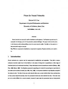
Fig. 2. Backpropagation of U (t) through the model neural network.
2) Path 2 represents the outputs of the action neural network fed into the model neural network #2. These outputs are , and . 3) Path 3 represents the outputs of the plant fed into the ac, tion neural network. These outputs are , and . 4) Path 4 represents a backpropagated signal of the output of the Critic neural network #2 through the model neural network with respect to path 1 inputs. The backpropagated signal on path 4 is in (5). 5) Path 5 represents a backpropagated signal of the output of the critic neural network #2 through the Model neural network with respect to path 2 inputs. The backpropagated signal on path 3 is in (5). 6) Path 6 represents a backpropagation output of path 5 signal ((iv) above) with respect to path 3. The signal on path 6 is in (5). 7) Path 7 is the sum of the path 4 and path 6 signals resulting , given in (5). in
8) Path 8 is the backpropagated signal of the term (Fig. 2) with respect to path 3 and is in (6). 9) Path 9 is a product of the discount factor and the path 7 signal, resulting in term in in (6). 10) Path 10 represents the output of the critic neural network . #1, (Fig. 2). 11) Path 11 represents the term given in (6) and as follows: 12) Path 12 represents
The partial derivatives of the utility function with re, and , and , spect to respectively, are obtained by backpropagating the utility functhrough the model network [29] as shown in Fig. 2. tion, The adaptation of the action network in Fig. 1, is illustrated back through the model in Fig. 3 which propagates network to the action network. The goal of such adaptation can be expressed as follows [35], [36]: (7) The error signal for the Action network adaptation is, therefore, given as follows: (8)
VENAYAGAMOORTHY et al.: IMPLEMENTATION OF ADAPTIVE CRITIC-BASED NEUROCONTROLLERS
1051
Fig. 3. DHP Action network adaptation. Backpropagation paths—dashed lines. The output of the critic �(t + 1) at time (t + 1) is backpropagated through the model from its outputs to its inputs, and the resulting vector is multiplied by and added to @U (t)=@A(t). Then an incremental adaptation of the action network is carried in accordance with (9).
The weights’ update expression [35] when applying backpropagation is as follows:
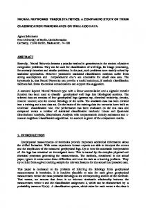
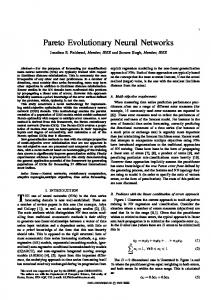
(9) are weights of the where is a positive learning rate and DHP Action neural network. The word “Dual” is used to describe the fact that the target outputs for the DHP Critic training are calculated using backpropagation in a generalized sense; more precisely, it does use dual subroutines (states and co-states) to backpropagate derivatives through the model and action neural networks, as shown in Fig. 1. The dual subroutines and more explanations are found in [33] and [39]. III. MULTIMACHINE POWER SYSTEM The micromachine laboratory at the University of Natal in Durban, South Africa has two microalternators, and each one represents both the electrical and mechanical aspects of a typical 1000 MW alternator. All the per-unit parameters are the same as those normally expected for 1000 MW alternators. The machine parameters were determined by the standard IEEE methods and are given for microalternators #1 and #2 in Tables I and II, respectively [40]. A practical laboratory three machine power system shown in Fig. 4 is set up by using the two microalternators/turbogenerators and the infinite bus as the third machine. A photo of the laboratory consisting of microalternators, transmission line simulators, high computing machine, etc. is shown in Fig. 5. The block diagram of the exciter and AVR combination is is given by (10). shown Fig. 6 where the saturation factor The AVR and exciter time constants are given in Table III (10) An interconnected power system, depending on its size, has hundreds to thousands of modes of oscillations. In the analysis
TABLE I MICROALTERNATOR #1 PARAMETERS
TABLE II MICROALTERNATOR #2 PARAMETERS
and control of system stability, two distinct types of system oscillations are usually recognized. One type is associated with generators at a generating station swinging (or oscillating) with respect to the rest of the power system. Such oscillations are referred to as “local plant mode” oscillations. The frequencies of these oscillations are typically in the range 0.8–2.0 Hz. The second type of oscillations is associated with the swinging of many generators in the one part of the power system against generators in other parts. These are referred to as “inter-area mode” oscillations, and have frequencies in the range 0.1–0.7 Hz. The basic function of the power system stabilizer is to add damping to both types of system oscillations. Other modes which may be influenced by a PSS include torsional modes, and control modes such as the “exciter mode” associated with the excitation system and the field circuit [41]. The block diagram of a typical PSS used to achieve damping of the system oscillations is shown in Fig. 7 [38]. The considerations and procedures used in the selection of the PSS parameters are similar to those found in [38] and these parameters are given in Table IV. A separately excited 5.6–kW dc motor is used as a prime mover, called the microturbine, to drive the microalternator. The torque-speed characteristic of the dc motor is controlled to follow a family of rectangular hyperbola in order to emulate different positions of the steam valve, as would occur in a
1052
IEEE TRANSACTIONS ON NEURAL NETWORKS, VOL. 14, NO. 5, SEPTEMBER 2003
Fig. 4. Multimachine power system consisting of two microalternators/turbogenerators G1 and G2 which are conventionally controlled by the AVRs, governors, and PSS.
Fig. 5. Micromachines laboratory at the University of Natal, Durban, South Africa.
real typical turbine. Appropriately scaled flywheels represent the different turbine inertia. The microturbine and governor transfer function block diagram is shown in Fig. 8, where is the turbine input power set point value, is the turbine is the speed deviation. The governor output power and and turbine time constants are given in Table V. Transmission lines are modeled using the laboratory transmission line simulator, which consists of banks of lumped inductors and capacitors, which can be switched in or out of the
circuit. Each inductance bank contains three of each of the following size inductors per phase: 1) 2) 3) 4)
0.005 0.007 0.010 0.012
p. u.; p. u.; p. u.; p. u.
These banks of lumped inductors and capacitors can be connected to represent transmission lines in excess of 1700 km, at
VENAYAGAMOORTHY et al.: IMPLEMENTATION OF ADAPTIVE CRITIC-BASED NEUROCONTROLLERS
1053
Fig. 6. Block diagram of the AVR and exciter combination.
TABLE III AVR AND EXCITER TIME CONSTANTS
400 kV. For the studies in this paper, only the inductance banks are used. IV. DSP IMPLEMENTATION PLATFORM NEUROCONTROLLERS
FOR THE
DHP
The critic, action, and model networks in Figs. 1 and 2 are all feedforward neural networks with three layers (input, hidden and output). The implementation of multilayered feedforward neural networks is a numerically computationally intensive process. The multiply–accumulate operations are very involved during both the forward and backward passes. Currently available DSPs that provide high computing power by employing a high-level of on-chip parallelism, integrated hardware multipliers, specific instruction sets, memory organization schemes and sophisticated addressing modes, provide a good choice for neural networks hardware implementation. This is because fast multiply–accumulate time, integrated on-chip random access memory (RAM), large addressing space and high precision are necessary for efficient virtual implementation of neural networks. For the hardware implementation described in this paper, one such device is the TMS320C6701 DSP on the Innovative Integration M67 card. This DSP is chosen in contrast to a FPGA for example, from the Xilinx XC4000 family, because of the user friendliness and support tools available when it comes to implementation of very intense complex codes, such as the adaptive critic designs implementation. The implementation of the DHP neurocontrollers on two generators simultaneously in a multimachine power system was not feasible on a PC hardware in the laboratory. The PC-based implementation will require maximum code optimization and the training cycles of the action and critic networks will be limited due to the slower platform speed especially with numerous I–O interfaces. Therefore, no comparison was carried out on timing
performances of the DSP against the PC. For the application considered in this paper, the cost of the DSP hardware is very small (less than 0.3%) compared to the cost of power plant. The DSPs intrinsic functions are used when appropriate. The huge computational power was used to the advantage of the application in implementing a dual DHP neurocontroller for two generators. The speed of the I–O capability and the interface with the A4D4-I/O card are exploited in this application. The critic, action (neurocontroller), and model neural networks are all implemented on the Innovative Integration M67 card [42] based on the TMS3 206 701 digital signal processor, operating at 160 MHz, hosted on a Pentium III 433 MHz personal computer. The M67 DSP card is equipped with two A/D conversion and D/A conversion modules [43]. The input and output signals of the laboratory microalternators differ in their range, the terminal voltage is 127 V, the speed is 1500 r/min, the exciter input voltage is 10 V and the turbine input voltage is 4 V. Therefore, the signals are all normalized before the neural network processing is carried out. An overview of the DSP hardware interface to the laboratory power system is shown in Fig. 9. The M67 DSP card and, the A/D and D/A modules are described briefly below. M67 DSP Hardware: The M67 card is a PCI bus compatible DSP card based upon the Texas Instruments TMS320C6701 floating point processor. Implementing a modular I–O expansion system, the M67 is particularly well suited to data acquisition and control tasks, and is supported by a collection of I/O bus function cards, which provide hardware interfacing to real-world equipment. Fig. 10 gives a block diagram of the M67 DSP card. The M67’s features include: 1) TMS320C6701 160 MHz processor; 2) 1.8 W Power consumption at 160 MHz; 3) optional external zero wait-state SBSRAM and one waitstate SDRAM memory pools; 4) two inter-board communications ports (up to 80 Mbytes/s transfer rate); 5) six channels of on-board timing (two on-chip timers, three custom 16-bit timers in FPGA logic and the 9850 DDS time-base); 6) OMNIBUS module compatible (two available slots on M67); 7) 32 bits of digital I–O;
1054
Fig. 7.
IEEE TRANSACTIONS ON NEURAL NETWORKS, VOL. 14, NO. 5, SEPTEMBER 2003
Block diagram of a typical conventional power system stabilizer.
TABLE IV PSS TIME CONSTANTS AND GAIN
8) two serial port connectors; 9) external mux board control connectors; 10) JTAG hardware emulation support. The OMNIBUS standards provide a fast, flexible, 32-bit wide mezzanine I–O expansion capability for Innovative Integration’s DSP and data acquisition boards. OMNIBUS compatible hosts can be equipped with modules supporting a wide range of I–O specifications and signal standards. The A4D4 OMNIBUS module [43] provides the target card processor with four channels of high-speed 200-kHz 16-bit resolution output A/D conversion per module slot. In addition, four channels of high-speed 200-kHz 16-bit resolution D/A conversion. The A4D4 module uses two pairs of Analog Devices AD976AA A/Ds with each channel having independent input six-pole anti-alias filters and programmable gain amplifiers for flexible input. Two pairs of Analog Devices AD7846 D/As with output amplifiers and independent channel filtering, gain, and trim, provide for high-speed data output signals. The four analog inputs on the A4D4 module are successive approximation type A/D converters, which allow for low data latency that is critical in control applications and multiplexed channel configurations. In addition, each A/D channel is calibrated for offset and gain errors allowing accurate measurements for a variety of applications. The converters can be triggered via hardware timer or software access and are capable of interrupting the target processor in interrupt driven applications. Fig. 11 shows the conceptual arrangement of the component circuitry featured on the board. The DSP card is equipped with two such modules.
stable. Then the action network is trained further while keeping the critic neural-network weights fixed. This process of training the critic and the action one after the other, is repeated until an acceptable performance is reached. It is assumed that there is no concurrent adaptation of the pretrained model neural network, briefly described below. The output of the microalternator is sampled at 50 Hz, allowing 20 ms for the critic and action training to take place. Model Neural Network: The model network training has been described for a multimachine power system in [10]. The same model network is used in the critic and action networks training and is shown in Fig. 12. The weights of the model network are fixed during the critic and action networks training. The sigmoidal functions in the hidden layer were computed on the DSP using the exp instruction of TMS320C6701. Training the Critic Neural Network: In the critic’s training cycle, an incremental optimization of (3) is carried out using a suitable optimization technique such as the backpropagation. The flowchart for the critic neural network (Fig. 13) training is given in Fig. 14. The functions , and represent the critic, action, and model neural networks with their weights , respectively. The critic neural network’s error and weight update equations and are given in (11) and (12) with the discount factor . The critic training is carried out for the learning rate cycles until the weights of the network have converged. is initialized to small random values at beginning of the training.
(11)
V. TRAINING PROCEDURE FOR THE CRITIC, ACTION, AND MODEL NEURAL NETWORKS (12) The training procedure is like the one suggested in [35] and it is applicable to any ACD. It consists of two separate training cy, and the other for the action . cles: one for the critic An important measure is that the action neural network is pretrained with conventional controllers (AVR and Governor) controlling the plant in a linear region. The critic’s adaptation is done initially with the pretrained action network, to ensure that the whole system, consisting of the ACD and the plant remains
where the utility function
is given by (13) [44]
(13)
VENAYAGAMOORTHY et al.: IMPLEMENTATION OF ADAPTIVE CRITIC-BASED NEUROCONTROLLERS
1055
Fig. 8. Block diagram of the microturbine and governor combination.
backward pass (BP) through the critic network, two BPs through the action network and two BPs through the model network. For the action network training (Fig. 2), it takes one FP through the critic network, one FP through the action network, one FP through the model network, one BP through the action network, and two BPs through the model network. Table VII gives the approximate critic and action networks’ training time per cycle. One cycle of critic and action training takes approximately 110 s. In a 20-ms sampling time, about 100–150 cycles of critic and action network trainings can be carried out, allowing enough time for other processing to take place. For all the calculations in this paper, the floating point format with 32-bit single precision was used.
TABLE V MICROTURBINE AND GOVERNOR TIME CONSTANTS
Training the Action Neural Network: The action neural network weights’ update expression [35], [36], when applying backpropagation, is as follows:
(14) is the weights of the action where 0.03 is the learning rate, neural network in the DHP scheme and the subscript A2 in (14) represents the DHP action. The flowchart for the adaptation of DHP action neural network (Fig. 15) is shown in Fig. 16. The cycles until the weights of action training is carried out for the network have converged. During the action network, training weights of the critic network are fixed. The overall training procedure of the DHP critic and action neural networks under the different conditions is shown in the flowchart in Fig. 17. The training of the critic and action neural networks are alternated until both networks have attained training convergence over a wide range of system operating conditions and configurations. It is important that the whole system consisting of the neurocontroller and the system remains stable while both of the critic and action networks undergo adaptation. Computation Cycles for Critic and Action Neural Networks: Table VI gives the approximate cycles and time required by the TMS320C6701 160-MHz processor for the forward and backward passes in the critic, action, and model neural networks. The add and multiply (MPY) instructions used here take one and four cycles, respectively. For the critic network training (Fig. 1), it takes two forward passes (FPs) through the critic network, one FP through the action network, two FPs through the model network, one
VI. RESULTS WITH THE DHP NEUROCONTROLLERS The two microalternators and the trained DHP neurocontrollers with fixed weights shown in Fig. 18 are now tested and their performances are evaluated against the conventional controllers and the power system stabilizer. The DHP neurocontroller sampling frequency is 50 Hz and the required time to do a forward pass through the action network with fixed weights is about 2.3 s. The training of the DHP neurocontroller is carried out in number of steps as explained in the paper. The offline training involves training the model, action, and critic neural networks. The Model training can take 60–100 s and the action and critic training can take 30–50 s. In addition to the offline training, an online training (natural training; see Fig. 17) is carried for another 30–50 s. But the time for the natural training depends on the different conditions under which the training is carried out and can take a longer time. Performance Evaluation of the Two DHP Neurocontrollers on Micro-Alternators #1 and #2: Once the DHP neurocontrollers’ weights have converged, the training is terminated and the neurocontrollers are allowed to control the microalternators with their weights fixed. The DHP neurocontrollers are tested for dynamic and transient operation for the following three disturbances: • an inductive load addition along the transmission line by closing switch S1; • an increase in the transmission line impedance by opening switch S2; • a temporary three-phase short circuit on bus 7. The tests carried out with different controller combinations are summarized in Table VIII. The performances of DHP neurocontrollers (case studies c) in all the above tests are compared
1056
IEEE TRANSACTIONS ON NEURAL NETWORKS, VOL. 14, NO. 5, SEPTEMBER 2003
Fig. 9. Overview of the data capturing and processing system interface to the power system.
Fig. 10.
Innovative Integration M67 DSP card block diagram.
against that of the conventional controllers, the AVR and governor (case studies a), as well as with that of a governor plus an AVR equipped with a PSS (case studies b), for different operating points. Measured results are presented for two opp.u. and p.u. and erating points, namely: 1)
2) p.u. and p.u. (at bus bars 1 and 2 in Figs. 4 and 18). The PSS parameters are carefully tuned [38] for the p.u., p.u., first set of operating condition ( p.u., p.u.). The two microalternators and with their trained DHP neurocontrollers and fixed weights are
VENAYAGAMOORTHY et al.: IMPLEMENTATION OF ADAPTIVE CRITIC-BASED NEUROCONTROLLERS
Fig. 11.
1057
A4D4 OMNIBUS module block diagram.
Fig. 12. Model neural-network structure with 12 inputs, 14 sigmoidal hidden layer neurons, and two linear neurons.
Fig. 13. DHP Critic neural-network structure with six inputs, ten sigmoidal hidden layer neurons, and two linear neurons.
now tested and their performances are evaluated against the conventional controllers and the power system stabilizer. Case Study 1: An Inductive Load Addition at the First Opp.u., p.u.): At the first erating Condition ( p.u. at power operating condition, an inductive load, factor (pf) of 0.85, is added to the transmission line at bus
Fig. 14.
Flowchart for the DHP critic neural-network training.
7 by closing switch S3 at time s. Fig. 19 shows the load angle response of microalternator #2 for the three different controller combinations (case studies 1a to 1c), since
1058
IEEE TRANSACTIONS ON NEURAL NETWORKS, VOL. 14, NO. 5, SEPTEMBER 2003
Fig. 15. DHP action neural-network structure with six inputs, ten sigmoidal hidden layer neurons, and two linear output neurons.
Fig. 17.
Fig. 16.
Flowchart for the DHP action neural-network training.
the load angle is widely accepted as measure of controller damping. The DHP neurocontrollers (case study 1c) ensure minimal overshoot on the load angle unlike with the conventional controllers. This is to be expected since the AVR and the governor parameters have been tuned for only small disturbances at this operating point. The terminal voltage response of microalternator #2 is not shown, because relatively little disturbance and improvement are experienced since the fault is closer to microalternator #1. For the same disturbance, the load angle response of microalternator #1 is shown in Fig. 20. The PSS (case study 1b) on microalternator #1 improves the performance of the conventional controllers. It is clear that the two DHP neurocontrollers (case study 1c) give the best performance of the three different controller combinations (case studies 1a–1c). Case Study 2: An Addition of a Series Transmission p.u., Line at the First Operating Condition ( p.u.): At the first operating condition, the series s transmission line impedance is increased at time p.u. to p.u. from by opening switch S2. Fig. 21 shows the load angle response
Overall training steps for the DHP critic and action neural networks.
of microalternator #2 for this test with the three different controller combinations. Clearly the DHP neurocontrollers (case study 2c) again exhibit superior damping and allow lesser overshoots compared to the performance of the conventional controllers even when equipped with a PSS. The load angle response of microalternator #1 for the same disturbance is shown in Fig. 22. It is clear the DHP neurocontrollers exhibit the best damping of the controllers. Case Study 3: A Temporary 125 ms 3-Phase Short Circuit p.u. and at the First Operating Condition ( p.u.): At the first operating condition, a temporary 125 ms dus. ration three-phase short circuit at bus 7 is carried out at Figs. 23 and 24 show the terminal voltage and the load angle responses of microalternator #2 for this test with the three different controller combinations. The fault is placed close to microalternator #1 and as a result the disturbance is felt more severe on microalternator #1 than on microalternator #2. Fig. 25 shows the load angle response of microalternator #1. Case Study 4: An Inductive Load Addition at the Second Opp.u. and p.u.): At the erating Condition ( p.u. second operating condition, an inductive load, at power factor (pf) of 0.85, is added to the transmission line at s. Fig. 26 shows the bus 7 by closing switch S3 at time load angle response of microalternator #2 for the three different controller combinations. The two DHP neurocontrollers (case study 4c) ensure minimal overshoot and better damping on the load angle compared to the other controller combinations. This is to be expected since the conventional AVR and the governor parameters have been tuned for only small disturbances at the first operating point. For the same disturbance, the load angle response of microalternator #1 is shown in Fig. 27. The PSS (case study 4b) on microalternator #1 improves the performance of
VENAYAGAMOORTHY et al.: IMPLEMENTATION OF ADAPTIVE CRITIC-BASED NEUROCONTROLLERS
1059
TABLE VI FORWARD AND BACKWARD PASS CYCLES AND TIME BASED ON A 160-MHZ CLOCK SPEED
TABLE VII CRITIC AND ACTION NETWORK TRAINING TIME
Fig. 18.
Multimachine power system consisting of turbogenerators G1 and G2 controlled by DHP neurocontrollers.
the conventional controllers. It is clear that the two DHP neurocontrollers again give the best performance of the four different controller combinations. The neurocontrollers have also been tested at other operating points for the transmission line impedance change and the three-phase short circuits. Compared to the conventional controllers, the neurocontrollers’ performance never degraded during these tests and the DHP neurocontrollers consistently had better damping. Depending on the type of test carried out, the DHP neurocontrollers have settling times faster than that with the other controllers by 2–10 s. This improvement in
controller performance is significant and plays a major role in restoring power plants that are operating close to their stability limits and undergoing severe disturbances, like a three-phase short circuit. In order to implement these DHP neurocontrollers on a commercial power station platform, a procedure similar to the laboratory will have to be carried out but in a stepwise fashion, like starting with a supplementary DHP neurocontroller to the AVR and eventually over time replacing the AVR first, and then the governor as well. The DHP neurocontrollers could be implemented on a number of commercially available
1060
IEEE TRANSACTIONS ON NEURAL NETWORKS, VOL. 14, NO. 5, SEPTEMBER 2003
TABLE VIII SUMMARY OF TEST CARRIED OUT
DSP or microprocessor platforms that have high precision (32 bits or higher) and clock speeds of at least 100 MHz allowing a number of critic and action neural-network training cycles within a sample period of 50–60 Hz. The DSP platform used in the laboratory implementation in this paper can be the starting implementation platform for a commercial power
station. Cost of the DSP implementation platform will not be a major consideration since it would be a small fraction of the overall cost of the power plant. The first problem would probably be in persuading operators of power plants to accept this new unknown technology, and initially one would probably still need the conventional controllers to be on standby in parallel to the
VENAYAGAMOORTHY et al.: IMPLEMENTATION OF ADAPTIVE CRITIC-BASED NEUROCONTROLLERS
1061
Fig. 19.
Load angle of alternator #2 for an inductive load addition at bus 7 for P = 0:2 p.u. and Q = 0 p.u.
Fig. 20.
Load angle of alternator #1 for an inductive load addition at bus 7 for P = 0:2 p.u. and Q = 0 p.u.
Fig. 21.
Load angle of alternator #2 for series transmission line impedance increase by opening switch S2 for P = 0:2 p.u. and Q = 0 p.u.
Fig. 22.
Load angle of alternator #1 for series transmission line impedance increase by opening switch S2 for P = 0:2 p.u. and Q = 0 p.u.
neurocontrollers with the ability to rapidly switch from one to the other in the event of a malfunction with the neurocontrollers. When solid-state diodes were first used in high power rectifiers during the early 1960s, many customers insisted on having their tried and trusted mercury arc rectifier on standby with a changeover switch in case the new diodes malfunctioned. The second problem would be to obtain sufficient training data for a wide range of operating conditions which could take minutes, hours, or even days to obtain. The Model neural
network will have to be trained first and then followed by the action and the critic neural networks. VII. CONCLUSION An adaptive critic design based DHP neurocontroller strategy has been proposed and implemented on an Innovative Integration M67 DSP hardware platform in real time to control the exciters and turbines of multiple turbogenerators in a power
1062
IEEE TRANSACTIONS ON NEURAL NETWORKS, VOL. 14, NO. 5, SEPTEMBER 2003
Fig. 23.
Terminal voltage of alternator #2 for a temporary 125 ms 3-phase short at bus 7 for P = 0:2 p.u. and Q = 0 p.u.
Fig. 24.
Load angle of alternator #2 for a temporary 125 ms three-phase short at bus 7 for P = 0:2 p.u. and Q = 0 p.u.
Fig. 25.
Load angle of alternator #1 for a temporary 125 ms 3 phase short at bus 7 for P = 0:2 p.u. and Q = 0 p.u.
Fig. 26.
Load angle of alternator #2 for an inductive load addition at bus 7 for P = 0:3 p.u. and Q = 0 p.u.
system. These hardware implementation studies on detailed specially designed turbogenerator systems have evaluated the robust performance of the adaptive critic design-based neurocontrollers. Once the critic and action neural networks have converged the parameters of the neurocontroller are fixed. This leads to the fact that there are no adaptive parameters with the neurocontroller online and therefore avoids the risk of instability. The convergence guarantee of the critic and action neural networks during offline training has been shown in
[30], [45]. In addition, the enormous computational load only arises during the offline training phase which is handled by the M67 DSP card, and therefore makes the online real-time implementation cost of the neurocontrollers cheaper. The DHP neurocontrollers have better damping when compared to the conventional controllers (which are fine tuned at particular operating point and system configuration) even when equipped with a power system stabilizer, especially when the operating conditions and system configurations changes. Such neurocon-
VENAYAGAMOORTHY et al.: IMPLEMENTATION OF ADAPTIVE CRITIC-BASED NEUROCONTROLLERS
Fig. 27.
1063
Load angle of alternator #1 for an inductive load addition at bus 7 for P = 0:3 p.u. and Q = 0 p.u.
trollers replacing conventional automatic voltage regulators and governors could allow power plants to be operated closer to their steady-state stability limits, thus producing more electrical power per dollar invested. ACKNOWLEDGMENT The authors gratefully acknowledge the University of Natal, Durban, South Africa, for allowing the usage of the micromachines laboratory. REFERENCES [1] B. Adkins and R. G. Harley, The General Theory of Alternating Current Machines. London, U.K.: Chapman and Hall, 1975. [2] Q. Lu and Y. Sun, “Nonlinear stabilizing control of multimachine systems,” IEEE Trans. Power Syst., vol. 4, pp. 236–241, Feb. 1989. [3] W. Mielczarski and A. Zajaczkowski, “Nonlinear field voltage control of a synchronous generator using feedback linearization,” Automatica, vol. 30, pp. 1625–1630, 1994. [4] J. W. Chapman, M. D. Ilic, C. A. King, L. Eng, and H. Kaufman, “Stabilizing a multimachine power system via decentralized feedback linearizing excitation control,” IEEE Trans. Power Syst., vol. 8, pp. 830–839, Aug. 1993. [5] Y. Wang, D. J. Hill, L. Gao, and R. H. Middleton, “Transient stability enhancement and voltage regulation of power system,” IEEE Trans. Power Syst., vol. 8, pp. 620–627, Apr. 1993. [6] Y. Wang, G. Guo, D. J. Hill, and L. Gao, “Nonlinear decentralized control for multimachine power system transient stability enhancement,” in Proc. 1995 Stockholm Power Tech Conf., pp. 435–440. [7] Z. Qiu, J. F. Dorsey, J. Bond, and J. D. McCalley, “Application of robust control to sustained oscillations in power systems,” IEEE Trans. Circuits Syst. I, vol. 39, pp. 470–476, June 1992. [8] K. J. Hunt, D. Sbarbaro, R. Zbikowski, and P. J. Gawthrop, “Neural networks for control systems—A survey,” Automatica, vol. 28, no. 6, pp. 1083–1112, 1992. [9] K. S. Narendra and K. Parthasarathy, “Identification and control of dynamical systems using neural networks,” IEEE Trans. Neural Networks, vol. 1, pp. 4–27, Mar. 1990. [10] G. K. Venayagamoorthy, R. G. Harley, and D. C. Wunsch, “Experimental studies with continually online trained artificial neural network identifiers for multiple turbogenerators on the electric power grid,” in Proc. IEEE-INS Int. Joint Conf. Neural Networks 2001, vol. 2, Washington, DC, pp. 1267–1272. [11] P. Shamsollahi and O. P. Malik, “Real-time implementation and experimental studies of a neural adaptive power system stabilizer,” IEEE Trans. Energy Conv., vol. 14, pp. 737–742, Sept. 1999. [12] , “Direct neural adaptive control applied to synchronous generator,” IEEE Trans. Energy Conv., vol. 14, pp. 1341–1346, Dec. 1999. [13] T. Kobayashi and A. Yokoyama, “An adaptive neuro-control system of synchronous generator for power system stabilization,” IEEE Trans. Energy Conv., vol. 11, pp. 621–630, Sept. 1996. [14] Y. Zhang, O. P. Malik, and G. P. Chen, “Artificial neural network power system stabilizers in multi-machine power system environment,” IEEE Trans. Energy Conv., vol. 10, pp. 147–155, Mar. 1995. [15] Y. M. Park, S. H. Hyun, and J. H. Lee, “A synchronous generator stabilizer design using neuro inverse controller and error reduction network,” IEEE Trans. Power Syst., vol. 11, pp. 1969–1975, Nov. 1996.
[16] Y. L. Abdel-Magid, M. A. Abido, and A. H. Mantawy, “Robust tuning of power system stabilizers in multimachine power systems,” IEEE Trans. Power Syst., vol. 15, pp. 735–740, May 2000. [17] Y. L. Abdel-Magid, M. A. Abido, S. Al-Baiyat, and A. H. Mantawy, “Simultaneous stabilization of multimachine power systems via genetic algorithms,” IEEE Trans. Power Syst., vol. 14, pp. 1428–1439, Nov. 1999. [18] E. Swidenbank, S. McLoone, D. Flynn, G. W. Irwin, and B. W. Hogg, “Neural network based control for synchronous generators,” IEEE Trans. Energy Conv., vol. 14, pp. 1673–1679, Dec. 1999. [19] M. M. Salem, A. M. Zaki, O. A. Mahgoub, E. A. El-Zahab, and O. P. Malik, “Studies on a multi-machine power system with a neural network based excitation controller,” in Proc. IEEE PES Winter Meeting, 2000, pp. 105–110. [20] Q. H. Wu, B. W. Hogg, and G. W. Irwin, “A neural network regulator for turbogenerators,” IEEE Trans. Neural Networks, vol. 3, pp. 95–100, Jan. 1992. [21] D. Flynn, S. McLoone, G. W. Irwin, M. D. Brown, E. Swidenbank, and B. W. Hogg, “Neural control of turbogenerator systems,” Automatica, vol. 33, no. 11, pp. 1961–1973, 1997. [22] G. K. Venayagamoorthy and R. G. Harley, “Simulation studies with a continuously online trained artificial neural network controller for a microturbogenerator,” in Proc. Inst. Elect. Eng. Int. Conf. Simulation, vol. 457, 1998, pp. 405–412. , “A continually online trained neurocontroller for excitation and [23] turbine control of a turbogenerator,” IEEE Trans. Energy Conversion, vol. 16, pp. 261–269, Feb. 2001. [24] P. Parks, “Liapunov redesign of model reference adaptive control systems,” IEEE Trans. Automat. Contr., vol. AC-11, pp. 362–367, Mar. 1966. [25] P. Osburn, H. Whitaker, and A. Kezer, “New developments in the design of model reference adaptive control systems,” in Proc. IAS 29th Annu. Meeting, New York, 1961. [26] R. M. Sanner and J. E. Slotine, “Gaussian networks for direct adaptive control,” IEEE Trans. Neural Networks, vol. 3, pp. 837–863, Nov. 1992. [27] M. I. Jordan and D. E. Rumelhart, “Forward models: Supervised learning with a distal teacher,” Cogn. Sci., vol. 16, pp. 307–354, 1992. [28] A. U. Levin and K. S. Narendra, “Control of nonlinear dynamical systems using neural networks: Controllability and stabilization,” IEEE Trans. Neural Networks, vol. 4, pp. 192–206, Mar. 1993. [29] G. K. Venayagamoorthy, R. G. Harley, and D. C. Wunsch, “Comparison of heuristic dynamic programming and dual heuristic programming adaptive critics for neurocontrol of a turbogenerator,” IEEE Trans. Neural Networks, vol. 13, pp. 764–773, May 2002. [30] D. Prokhorov and L. A. Feldkamp, “Analyzing for Lyapunov stability with adaptive critics,” Proc. IEEE Int. Conf. Syst., Man, Cybern., vol. 2, pp. 1658–1661, 1998. [31] T. T. Shannon and G. G. Lendaris, “Qualitative models for adaptive critic neurocontrol,” in Proc. Int. Joint Conf. Neural Networks, vol. 1, 1999, pp. 455–460. [32] Z. Huang and S. N. Balakrishnan, “Robust adaptive critic based neurocontrollers for systems with input uncertainties,” in Proc. Int. Joint Conf. Neural Networks, vol. 3, 2000, pp. 67–72. [33] P. J. Werbos, “Approximate dynamic programming for real-time control and neural modeling,” in Handbook of Intelligent Control, White and Sofge, Eds: Van Nostrand Reinhold, pp. 493–525. [34] C. Watkins and P. Dayan, “Q-learning,” Machine Learning, vol. 8, pp. 279–292, 1992. [35] D. Prokhorov and D. C. Wunsch, “Adaptive critic designs,” IEEE Trans. Neural Networks, vol. 8, pp. 997–1007, Sept. 1997. [36] D. Prokhorov, “Adaptive Critic Designs and Their Applications,” Ph.D. dissertation, Texas Tech Univ., Lubbock, TX, 1997.
1064
[37] W. K. Ho, C. C. Hang, and L. S. Cao, “Tuning of PID controllers based on gain and phase margin specifications,” in Proc. 12th Triennial World Congr. Automat. Contr., 1993, pp. 199–202. [38] P. Kundur, M. Klein, G. J. Rogers, and M. S. Zywno, “Application of power system stabilizers for enhancement of overall system stability,” IEEE Trans. Power Syst., vol. 4, pp. 614–626, May 1989. [39] P. J. Werbos, Roots of Backpropagation. New York: Wiley, 1994. [40] D. J. Limebeer, R. G. Harley, and S. M. Schuck, “Subsychronous resonance of the koeberg turbogenerators and of a laboratory microalternator system,” Trans. SA Inst. Elect. Eng., pp. 278–297, Nov. 1979. [41] P. Kundur, D. C. Lee, and H. M. Z. El-Din, “Power system stabilizers for thermal units: Analytical techniques and on-site validation,” IEEE Trans. Power App. Syst., vol. PAS-100, pp. 81–95, Jan. 1981. [42] M6x/cM6x Development Package Manual, Innovative Integration, Simi Valley, CA, 2000. [43] OMNIBUS User’s Manual, Innovative Integration, Simi Valley, CA, 2001. [44] G. K. Venayagamoorthy, R. G. Harley, and D. C. Wunsch, “Dual heuristic programming excitation neurocontrol for generators in a multimachine power system,” IEEE Trans. Ind. Applicat., vol. 39, pp. 382–394, Mar./Apr. 2003. [45] D. Prokhorov and D. C. Wunsch, “Convergence of critic-based training,” in Proc. IEEE Int. Conf. Systems, Man, Cybernetics, vol. 4, 1997, pp. 3057–3060.
Ganesh Kumar Venayagamoorthy (S’91–M’97– SM’02) was born in Jaffna, Sri Lanka. He received the B.Eng. degree with first-class honors in electrical and electronics engineering from the Abubakar Tafawa Balewa University, Bauchi, Nigeria, and the M.Sc.Eng. and Ph.D. degrees in electrical engineering from the University of Natal, Durban, South Africa, in 1994, 1999, and 2002, respectively. From March 1996 to April 2001 and May 2001 to April 2002, he was a Lecturer and a Senior Lecturer, respectively, with the Durban Institute of Technology, Durban, South Africa, where he lectured Control Systems and Signal Processing among other courses. He was a Research Associate at the Texas Tech University, Lubbock, in 1999 and at the University of Missouri-Rolla, from 2000 to 2001. He is currently an Assistant Professor at the University of Missouri-Rolla, USA. His research interests are in computational intelligence, control systems, power systems and evolving hardware. He has authored over 70 papers in refereed journals and international conferences. Dr. Venayagamoorthy received the 2001 IEEE Neural Network Society Summer Research Scholarship and the 2003 International Neural Network Society Young Investigator award recipient. He is a member of South African Institute of Electrical Engineers and the International Neural Netowrk Society. He was Technical Program Co-Chair of the International Joint Conference on Neural Networks (IJCNN) 2003, Portland, OR. He is Technical Program Co-chair for the 2004 International Conference on Intelligent Sensing and Information Processing (ICISIP), Chennai, India.
IEEE TRANSACTIONS ON NEURAL NETWORKS, VOL. 14, NO. 5, SEPTEMBER 2003
Ronald G. Harley (M’77–SM’86–F’92) was born in South Africa. He received the BSc.Eng. (cum laude) and M.Sc.Eng. (cum laude) degrees from the University of Pretoria, Pretoria, South Africa, and the Ph.D. degree from London University, London, U.K., in 1960, 1965, and 1969, respectively. In 1970, he was appointed to the Chair of Electrical Machines and Power Systems at the University of Natal in Durban, South Africa. He is currently the Duke Power Distinguished Professor at the Georgia Institute of Technology, Atlanta. He has coauthored approximately 280 papers in refereed journals and international conferences. Nine papers received prizes from journals and conferences. His research interests are in the dynamic and transient behavior of electric machines and power systems, and controlling them by the use of power electronics and modern control algorithms. Dr. Harley is a Fellow of the SAIEE and a Fellow of the Institution of Electrical Engineers (IEEE). He is also a Fellow of the Royal Society in South Africa, a Fellow of the University of Natal, and a Founder Member of the Academy of Science in South Africa formed in 1994. He has been elected as a Distinguished Lecturer by the IEEE Industry Applications Society for the years 2000 and 2001. He is currently the elected Vice-President of Operations of the IEEE Power Electronics Society.
Donald C. Wunsch (SM’94) received the B.S. degree in applied math from the University of New Mexico, Albuquerque, in 1984 and the M.S. degree in applied math and the Ph.D. degree in electrical engineering from the University of Washington, Seattle, in 1987 and 1991. He was Senior Principal Scientist at Boeing, where he invented the first optical implementation of the ART1 neural network, featured in the 1991 Boeing Annual Report, and other optical neural networks and applied research contributions. He has also worked for International Laser Systems and Rockwell International. From 1993 to 1999, he was Assistant, then Associate Professor of Electrical and Computer Engineering, and Computer Science, at Texas Tech University. Since 1999, he is the Mary K. Finley Missouri Distinguished Professor of Computer Engineering in the Department of Electrical and Computer Engineering, University of Missour– Rolla. He heads the Applied Computational Intelligence Laboratory and also has a joint appointment in Computer Science. Research activities include adaptive critic designs; neural network pattern analysis, optimization, forecasting and control; bioinformatics; financial engineering; fuzzy risk assessment for high-consequence surety; graph theory; computer security; and Go. He has over 200 research publications in various aspects of computational intelligence. Dr. Wunsch is an Academician in the International Academy of Technological Cybernetics, and in the International Informatization Academy; and is recipient of the Halliburton Award for Excellence, and a National Science Foundation CAREER Award. He is a Member of the International Neural Network Society (INNS), Association for Computing Machinery, Phi Kappa Phi, a Life Member of the American Association of Artificial Intelligence, a Life Member of Sigma Xi, and previously served as an Associate Editor of the IEEE TRANSACTIONS ON NEURAL NETWORKS and voting member of the IEEE Neural Network Council. He was elected as a Board of Governors member of the INNS, and served as Local Arrangements Chair for the International Joint Conference on Neural Networks (IJCNN) 91, Technical Co-Chair for IJCNN 02 and General Chair for IJCNN 03.