Nonlinear Adaptive Flight Control using Neural Networks ... - CiteSeerX
Recommend Documents
Model-free adaptive control approaches are worthwhile to be investigated for fault tolerant flight control due to many unsolved challenges in model-based ...
A neural-network-aided nonlinear dynamic inversion-based hybrid ... mass of the airplane, lb .... where UA is the forward velocity in feet per second, WA is the vertical ... mA is the airplane mass; TA is the thrust in pounds of force; α is the angl
Neural Networks architectures for modelling dynamic signals and systems ...
Chapters 4, 5 and 6 from [Haykin, 1994] S. Haykin Neural Networks – A ...
This feedforward model is called a rallying model. The equivalence is illustrated in Fig. 3: u. Model. (d=1) y. Theoretical. MR Controller. (E, H, d=1) r y. â. Model.
... genetic algorithm (GA), back-propagation (BP), and particle swarm optimization (PSO). .... Not logged in Google [Search Crawler] (3000811494) 66.249.65.74.
Feb 10, 2005 - Model Control (IMC) and Model Predictive Control (MPC), were modified to ... provide a flexible basis for adaptive nonlinear controllers. This.
Lemma 4: For the first-order system (8), if the practical ro- bust control ... proposed controller (18) in Lemma 4 is not feasible due to the ..... by Barbalat's lemma,.
The design of an adaptive backstepping flight control law for the F-16/MATV (multi-axis thrust vectoring) .... The outline of this paper is as follows: First, the flight dynamics of ...... âIntelligent Control of Un-Manned Air Vehicles: Program Sum
Carretera Pachuca -Cd. Sahagún, km 20, Zempoala, Hidalgo, MÃXICO [email protected] http://www.upp.edu.mx. Abstract: - The doubly fed induction generator ...
In this paper, PID neural network, which is an adaptive controller, has analyzed and compared with two other conventional PID algorithms through computer ...
KEY WORDS: diesel engines; mean value model; dynamic optimization .... that searches for the optimal control variables of the engine under steady state would ...
includes engine dynamics and detailed nonlinear actuator models. The model .... GA have become a popular, robust search and optimisation technique for ...
Abstract| In this paper neural network approach for nonlinear noise and interference cancellation is de- veloped . The Hyper Radial Basis Function (HRBF).
Although adaptive controllers [1-5, 7] can achieve fine control and compensate ..... Proof: 1. To prove |Îg| ⤠gM, let Vg = 1. 2γ2 tr. [. ÎT g Îg. ] , then . Vg = 1 γ2 tr.
Neural Networks. Abstract. Adaptive learning is the core technology behind intelligent tutoring systems, which are responsible for estimating student knowledge ...
School of Computer Science. Carnegie Mellon University. Pittsburgh, PA 15213, USA [email protected]. Eunhee Rhim. Samsung Electronics Co., Ltd. Suwon ...
vehicle is damaged. Although a number of ad ... ington.edu). A. J. Calise is with the School of Aerospace Engineering, Georgia In- .... The flight mechanics of a tiltrotor present both opportunities ...... Control Conf. , San Diego, CA, Jun. 1999, pp
Knowledge Engineering and Discovery Research Institute, Auckland University of Technology, New. Zealand ... challenging aspects for neuroscientists is that current technologies can not keep track ... information processing with biological relevance,
Today, artificial neural networks are an important area of study within the field of applied artificial intelligence. ..... Handbook, Fundamentals SI Edition. Atlanta ...
damage and hydraulic loss over Baghdad [21], and the Sioux City, Iowa accident involving United Airlines Flight 232. [22]. The dissimilar actuator rates can ...
USING A RECURRENT NEURAL NETWORK. HENRIQUES, J. and DOURADO, A. CISUC - Centro de Informática e Sistemas da Universidade de Coimbra.
Mailing address: Francisco ... Fax : 56-2-6811140. Email: [email protected] ... differential equations representing mass or energy balances. In polymeric ...
ADAPTIVE CONTROL USING A HYBRID-NEURAL MODEL: ... the MPC formulations, make an attractive combination for the control of a polimerization reactor.
Nonlinear Adaptive Flight Control using Neural Networks ... - CiteSeerX
Feedback linearization and adaptive neural networks provide a powerful controller ... of Aerospace, Phone: (404) 894-7145, E-mail: [email protected] .... on the role of NN technology in flight control system design have been ...
Nonlinear Adaptive Flight Control using Neural Networks Rolf T. Rysdyk✝ Anthony J. Calise∗ Georgia Institute of Technology School of Aerospace Engineering Atlanta, GA, 30332
Abstract Feedback linearization and adaptive neural networks provide a powerful controller architecture. This paper surveys the status of nonlinear, and adaptive flight control, and summarizes the research being conducted in this area in the School of Aerospace Engineering at the Georgia Tech. A description of the controller architecture and associated stability analysis is given, followed by a more in-depth look at its application to a tiltrotor aircraft. This is followed by a summary of future research directions, and possibilities for technology transition that are currently underway.
Introduction Aircraft flight control design has been dominated by classical control techniques. While this tradition has produced many highly reliable and effective control systems, recent years have seen a growing interest in applications of robust, nonlinear, and adaptive control theory. This development has been motivated in part by new possibilities offered by Active Control Technology (ACT). ACT applications include ‘fly-by-wire’ and ‘fly-by-light’ technologies, which creates opportunities for new concepts in aircraft design. Some examples are lowobservable and supermaneuverable tailless fighter aircraft, and aircraft capable of flight in multiple configurations, Fig 1. Next generation aircraft using ACT may differ even more radically from their conventional predecessors, presenting control designers with a variety of unprecedented challenges. Examples include remotely piloted and autonomous vehicles, which need not be constrained by physical limitations imposed by a human operator on board.
Fig. 1. XV-15 in helicopter configuration. ∗ ✝
Professor, School of Aerospace, Phone: (404) 894-7145, E-mail: [email protected] Senior Research Assistant.
1
The desire for enhanced agility and functionality demands that the aircraft perform over an increased range of operating conditions characterized by dramatic variations in dynamic pressure and nonlinear aerodynamic phenomena. Furthermore, the use of nonlinear actuation systems increases the complexity of the control design. Therefore, there is presently a strong interest in the development of real-time adaptive control methods that are applicable to flight control problems where the aircraft characteristics are poorly understood or are rapidly changing. In high angle-of-attack (AoA) flight, the aerodynamics are poorly understood and expensive to model. Alternately, variation in dynamic response may occur due to battle damage or component failure, requiring rapid on-line reconfiguration of the control system to maintain stable flight and reasonable levels of handling qualities. Traditional flight control designs involve linearizing the vehicle dynamics about several operating conditions throughout the flight envelope, designing linear controllers for each condition, and blending these point designs with an interpolation scheme. This ‘gain-scheduling’ approach, which tends to be rather tedious, may produce a control law that does not globally possess the desirable properties exhibited locally by its constituent point designs. Although gainscheduling has historically proven successful in a variety of applications, future designs will benefit from more advanced methods which explicitly account for the intrinsic nonlinearities of the system. Nonlinear control techniques, such as feedback linearization, rely heavily upon accurate knowledge of the plant dynamics. However, some aerodynamic effects are very difficult to model. An example is the asymmetric nose vortex shedding that causes ‘phantom yaw’ in highAoA flight, [1]. The direction in which the vortex is shed is unpredictable, as it depends greatly on the imperfections in the surface of the vehicle. Accounting for such uncertain effects using robust control is, in general, a conservative approach and may sacrifice achievable performance. In contrast, a control system that adapts to the nonlinear dynamics of various flight regimes as they occur has the potential to achieve superior performance throughout the full envelope. To date, most adaptive flight control designs have addressed the issue of the uncertain aerodynamic effects within the context of linear control. Aircraft of the future will benefit from an adaptive control system based on the full nonlinear dynamics of the vehicle while avoiding prohibitively complex gain scheduling. Artificial ‘neural’ networks (NN’s), which have the ability to approximate general continuous nonlinear functions, are ideal for the adaptive flight control application. One advantage of the NN over simple table lookup approaches is the reduced amount of memory and computation time required. In addition, the NN can provide interpolation between training points with no additional computational effort. Furthermore, experience has shown that NN function as highly nonlinear adaptive control elements and offer distinct advantages over more conventional linear parameter adaptive controllers in achieving desired performance. This article is organized as follows. We first summarize the status of nonlinear, adaptive and NN applications with emphasis on flight control. This includes a summary of the flight control research activities at Georgia Tech in this area. Next, we describe the challenges associated with
2
modern tiltrotor technology, and illustrate the application of a NN to this research area. This is followed by discussions on future research directions, and possibilities for technology transition.
Status of Current Research Efforts Nonlinear Adaptive Flight Control The most widely studied approach to nonlinear control involves the use of nonlinear transformation techniques and differential geometry. This methodology transforms the state and/or control of the nonlinear system such that the resulting system exhibits linear dynamics. Linear tools can then be applied and subsequently converted back into the original coordinates via an inverse transformation. This broad class of techniques is most commonly known as ‘feedback linearization’. Isidori provides a comprehensive treatment of nonlinear transformation control techniques [2]. Feedback linearization theory has found many applications in flight control research. Meyer and Cicolani included the concept of a nonlinear transformation in their formal structure for advanced flight control [3]. Menon et-al., used a two-time-scale approach to simplify the linearizing transformations [4]. A specific case of feedback linearizing control, known as ‘dynamic inversion’, has been investigated at great length for application to supermaneuverable aircraft [5,6,7]. These studies show that dynamic inversion is an effective way of compensating for the nonlinearities associated with high AoA flight. As illustrated by Brinker and Wise, dynamic inversion can be vulnerable to modeling errors [8]. Therefore, a variety of robust nonlinear control schemes has been proposed. These techniques provide robustness to sources of uncertainty, which typically include unmodeled dynamics, parametric uncertainty, and uncertain nonlinearities [8,9,10]. One approach to the control of nonlinear systems, which does not rely on inversion, is the class of so-called ‘backstepping’ techniques [11]. Backstepping employs Lyapunov synthesis to recursively determine nonlinear controller for linear or nonlinear systems with a particular cascaded structure. The backstepping paradigm affords the control designer greater freedom in choosing the form of the feedback control [12,13]. Many of the results in adaptive control are derived from Lyapunov stability theory [14]. Although adaptive control has a long history, it did not gain favor until 1980, when important results guaranteeing closed-loop stability were obtained [15]. Parameter adaptive control schemes may be divided into direct and indirect methods. Indirect adaptive control involves online identification of plant parameters, based upon which a suitable control law is implemented. In case of direct adaptive control, the parameters defining the controller are updated directly. Several efforts concentrate specifically on adaptive control of feedback-linearizable systems [16,17]. The sensitivity of some adaptive schemes to disturbances and unmodeled dynamics prompted many researchers to investigate robust adaptive control for linear systems. Possible tools include the use of a dead-zone to maintain bounded errors in the presence of noise [18],
3
parameter projection techniques to provide robustness to unmodeled dynamics [19], and methods for improving robustness of adaptive nonlinear controllers using backstepping [20]. While treatment of disturbances and uncertain nonlinear functions has become somewhat common, fewer efforts have addressed robustness to unmodeled dynamics. Some exceptions include an application of robust adaptive nonlinear control to a high-performance aircraft [21], and a demonstration of the versatility of the backstepping design paradigm [22]. Neural Networks for Flight Control Because of their well known ability to approximate uncertain nonlinear mappings to a high degree of accuracy, NN’s have come to be seen as a potential solution to many outstanding problems in adaptive and/or robust control of nonlinear systems [23,24]. The literature includes numerous applications of NN’s to flight control systems, a selection of which will be discussed here. Baron et al., employed polynomial networks for fault detection and reconfigurable flight control [25]. Linse and Stengel demonstrated that NN’s could be used to identify aerodynamic coefficients [26]. Applications in which NN’s are used to control supermaneuverable aircraft are described by Baker and Farrell [27], and by Steck and Rokhasz [28]. Survey papers commenting on the role of NN technology in flight control system design have been contributed by Werbos [29] and Steinberg [30,31]. Our research has focused on the use of a direct NN based adaptive control architecture that compensates for unknown plant nonlinearities in a feedback linearizing control framework. Examples in the area of fighter aircraft flight control include [32,33]. Applications to advanced technology guided missiles and guided munitions have been treated in [34,35,36]. In [35], the issue of robustness to unmodeled actuator dynamics is treated by modifying the adaptation law. The modification uses the concept of dynamic nonlinear damping [12], which to our knowledge is the first time this has been developed for fully nonlinear adaptive systems. In [37], a stable adaptive algorithm is developed for multi-layer neural networks, applicable to general nonlinear systems (nonlinear both in states and controls). Robustness to actuator dynamics for this more general case is a topic of current research interest.
Fig.2. R-50 helicopter control application. Examples of applications to helicopters and tiltrotors may be found in [3839-4041]. In particular, we highlight an application to the XV-15 tiltrotor aircraft in the next section of this paper. In addition to these theoretical and application efforts, we have an experimental flight
4
research facility that utilizes two Yamaha R-50 remotely piloted helicopters, Fig 2. The facility is dedicated to flight testing of advanced control algorithms on helicopters. The facility is dedicated to flight testing of advanced control algorithms on helicopters. The helicopters are fully instrumented for flight control research, and will be used to demonstrate the NN based flight control architecture, described later.
Tiltrotor Handling Qualities Application This section details an application of a NN based adaptive controller architecture to the XV-15 tiltrotor aircraft. The primary objective is to provide the pilot with consistent handling qualities throughout all modes of flight. It requires only an approximate linear model at a single operating point. The architecture is based on the inversion of the linear model, augmented with an adaptive NN. Tiltrotor aircraft combine the hover performance and control of a helicopter with the cruise speed and efficiency of a turboprop airplane. As shown in Fig 3, tiltrotor aircraft feature wing tip mounted prop-rotors that can be rotated from a vertical orientation for take-off and landing to a horizontal position for efficient fixed-wing-borne flight for high speed cruise. The successful XV-15 tiltrotor research aircraft led to the V-22, Osprey, which has begun low rate serial production for the U.S. Marines and Air Force. Experience with both the XV-15 and V-22 led Bell Helicopter Textron International to commit to design and development of the first civil tiltrotor, the BB-609. Tiltrotor aircraft represent the first major new aircraft type to enter production since the supersonic transports of the 1970’s. Tiltrotor aircraft hold the promise of revolutionizing short-range air transportation. The military application, exemplified by the V-22, has a clear requirement for high cruise speeds and long ranges combined with vertical take-off and landings on board ships or into small clearings. Similarly, the six to nine passenger BB-609 shows immediate promise in search and rescue, resource development, utility, medical and executive transport roles. In the future, large tiltrotor transports, serving as regional airliners, promise to relieve growing conventional airport congestion by replacing commuter aircraft, and freeing up runway slots for larger jet transports. Such regional transport tiltrotors achieve this air-transportation-system capacity increase by operating into airport sites other than the active conventional runway and into urban vertiports located near commercial and population centers such as seen in Fig 3. The flight mechanics of a tiltrotor present both opportunities and challenges to the designer. Prop-rotor movement from the vertical, helicopter mode position toward the horizontal, airplane mode position rapidly accelerates the aircraft while orienting prop-rotor thrust to its optimum position. Conversely, up and aft movement of the prop-rotors, required to prepare for a vertical landing, provides the drag needed to decelerate but at the same time produces a generally undesirable additional lift which the pilot must counteract with appropriate flight path control. The shift between helicopter and airplane flight modes necessitates a change in control strategy. In helicopter mode, thrust is used for vertical control while pitch attitude is used for
5
velocity control. In airplane mode, these roles are exchanged, with thrust controlling airspeed and pitch attitude controlling vertical flight path angle. The exchanging uses of pitch attitude and thrust control combined with gross changes in aircraft response with flight condition present challenges to control system design. Current tiltrotor design practice provides a continuously active set of airplane controls (elevator, ailerons and rudders). Helicopter mode prop-rotor controls include collective pitch for thrust and power control and cyclic pitch for prop-rotor tilt. The helicopter rotor cyclic pitch controls are phased out at nacelle angles below 60 degrees.
Fig 3: Tiltrotor configurations and applications. Command Augmentation The wide range of flight dynamics with flight mode and condition, coupled with a variety of desired control response characteristics depending on the flight task provides an excellent opportunity for the application of adaptive flight control laws. Two common types of control augmentation for aircraft are referred to as Rate Command Attitude Hold (RCAH) and Attitude Command Attitude Hold (ACAH), [42]. Tactical military flight and day-visual civil flight tend toward a desire for angular rate response. As the visual cue environment degrades and flight path precision requirements increase as with civil ‘instrument flight rules’ (IFR), the need for tighter attitude control emerges. Codified for the military in ADS-33, [42], and recommended by the bulk of vertical flight aircraft handling qualities studies, this leads to a need for attitude stabilization and even attitude control for precise hovering and low speed flight in poor visibility conditions. Attitude command in pitch, roll and yaw (heading) are recommended for poor visibility hover control. As speed increases, the need for more roll maneuverability emerges, leading to a relaxation of roll control to a rate response type. Similarly, the desired control in
6
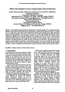
yaw axis changes from heading command to yaw rate control with turn coordination. The considerations involved in a tiltrotor IFR approach procedure, include [43]: 1. a conversion schedule of nacelle angle with speed, from cruise to helicopter configuration in the approach, and vice versa for the missed approach procedure, 2. deployment or retraction of flaps depending on nacelle angle, speed, and glide slope, 3. switching between augmentation types, and 4. desired altitude and speed trajectories. The tiltrotor poses a unique demand on the human operator since the control response changes as it converts from forward flight in cruise configuration to slow flight as a helicopter. Starting in airplane configuration, the throttle affects flight speed and the longitudinal control (“cyclic” or “stick”) is used to initiate climb or descend. As the aircraft decelerates and converts into a helicopter configuration these controls trade roles. The throttle now represents the “collective”, controlling climb and descend directly, the longitudinal control results in changes in speed. In all flight conditions, the primary effect of longitudinal control is a change in pitch attitude. The attitude response to a longitudinal control input is therefore of considerable interest. Neural Network Augmented Model Inversion Architecture This section details the architecture of the NN augmented model inversion as applied to the tiltrotor aircraft. Fig 4 contains a diagram of the architecture used for implementation of ACAH control in the pitch channel. The command filter serves both to limit the input rate, and as a model for desired response. This allows for straightforward implementation of ADS-33 handling qualities specifications. The presented architecture provides for excellent results in the longitudinal application, as is shown in following sections. Identical construction applies to the lateral channels. Results in the lateral channels show similar performance.
command filter
θ COM
&& θC
ΘC
θ Θ = & θ
~ Θ
linear controller
X U (θ )
UC
U AD
f$ −1 neural net
δ$ LON
X Aircraft
X
scaling
U
bias
Fig.4. Adaptive NN augmented model inversion architecture, in the longitudinal channel, configured for ACAH. Dynamic model inversion is used as the feedback linearization method of choice. The true aircraft is represented by the GTRS nonlinear model for the XV-15 [44]. The model
7
inversion control is based on dynamics linearized about a nominal operating point, with the rotor dynamics residualized, Eqn 1. ω& = A1 ⋅ x1 + A2 ⋅ ω + B ⋅ δ
(1)
where A1 , A2 and B represent respectively the aerodynamic stability and control derivatives at the nominal operating point, and ω = [ p q r ]T , contains the rates about the body fixed axes [45]. The collective / throttle control position is treated as one of the relatively slow translational states, x1 = u v w δ COL
[
]
body axes, δ = δ LAT
δ DIR
[
δ LON
T
. The inputs of interest are the controls of moments about the
]. T
One of the objectives of this section is to demonstrate how the NN is capable of adapting to errors caused by the linearized inverted model. Unmodeled dynamics originate from the linearization used in the derivation of the nominal inverting controller. This includes linearization of dynamics nonlinear in the control. Any cross-coupling between fast rotational states and slow translational states is neglected in the inversion as well. We consider inversion control using Eqn 1. This involves replacing the left-hand side of the equation with desired angular accelerations ( ω& D ), and solving for the control perturbations. From a generalization of the control architecture in Fig 4, the ‘pseudo control’, U , for the three rotational degrees of freedom is designed in terms of body angular rates as U = U C + ω& C − U AD
(2)
where U C is the output of a linear controller operating on an error signal. U C is used to specify the tracking error transient, which is designed to be fast relative to the dynamics of the command filter, yet slow relative to the actuator dynamics. Integral action is added to provide for attitude retention in a RCAH system. For example, in the roll-channel t
UC = KP ⋅ ~ p + KI ⋅ ∫ ~ p dτ
(3)
t0
p = pC − p . A similar representation is made for the directional channel. The potential where ~ for integrator wind-up is an issue of current research. To implement ACAH in the longitudinal channel, assuming control of the Euler angle, the linear controller can be designed as ~ ~& U C = K P ⋅ θ + KD ⋅ θ
(4)
The signal ω& C is constructed from the command filter output as
[
&& θC
ω& C = p& C
8
r&C
]
T
(5)
For the civilian tiltrotor application, the focus is on the approach to landing phase of flight. The combination of conversion and approach procedure calls for attitude stabilization in all channels. The need for precision during the final stages of flight benefits from ACAH in the longitudinal channel, yet the roll and yaw channels are RCAH. By using the relations between the Euler angular accelerations and the body angular accelerations, the desired acceleration can be solved for. The elements of the desired acceleration, ω& D = [ p& D q& D r&D ]T , for this combination are p&D = q&D =
where sφ is shorthand for sin(φ), etc. Substitution of ω& D in Eqn 1 and inverting results in δ = B −1 ⋅ {ω& D − A1 ⋅ x1 − A2 ⋅ ω}
(7)
Because in practice A1 , A2 , and B are not represented nor known exactly, we actually obtain
δ$ = B$ −1 ⋅ {ω& D − A$1 ⋅ x1 − A$ 2 ⋅ ω}
(8)
ε =& ω& − { A$ 1 ⋅ x1 + A$ 2 ⋅ ω + B$ ⋅ δ$ }
(9)
The inversion error is defined as
Notice, by combination of Eqn 10, and 11, that ε can be represented as a function of the states and the pseudo control. In particular in the pitch channel, the error is a function of U ( θ ) and U ( r ) . The effect of ε can be represented about the body-fixed axes as p& = ω& D (1) + ε (1) q& = ω& D ( 2) + ε ( 2) r& = ω& D ( 3) + ε ( 3)
(10)
Specifically, for the ACAH implementation in the longitudinal channel we may represent the effect of ε in the Euler pitch attitude dynamics as && θ = U ( θ ) + ε ( 2 ) ⋅ cφ − ε ( 3) ⋅ sφ Closing the loop by combining Eqn 2, 4, and 11 we obtain
9
(11)
~ ~& ~ && θ + K D ⋅ θ + K P ⋅ θ = U AD ( 2 ) − ε θ
(12)
where θ~ = θ C − θ , and ε θ = {ε ( 2) ⋅ cφ − ε ( 3) ⋅ sφ } is the pitch component of the inversion error when represented in the Euler frame. The left-hand side of Eqn 12 represents the tracking-error dynamics. The right-hand side is the network compensation error, which is a forcing function of the tracking error dynamics. In an ideal setting, the NN output, U AD ( 2 ) , completely cancels ε θ . Since the input to the NN includes the pseudo control signal, U , which in turn is a function of the output of the NN, U AD , a fixed point problem occurs. U is input to the NN through a ‘squashing’ function, Fig 4. This insures that at least one fixed point solution exists.
Neural Network Weight Adaptation This section derives a network adaptation law that guarantees boundedness of the tracking error and of the network weights. For a linear-in-the-parameters network U AD = W T (X, U) where W is a vector of network weights, and of selected elements of the state vector.
(13)
is a vector of basis functions, and X is made up
The error dynamics in the pitch channel, Eqn 12, can be rewritten as e& = Ae + b(U AD (2) −
)
(14)
with 0 A= − K P
1 − K D
(15)
~ ~& and e = [ θ θ ]T and b = [0 1]T . Denote an ideal weight vector as W * and define the ~ corresponding weight error as W = W − W * . Rewrite the error dynamics as
(
T ~ e& = Ae + bW T + b W * −
)
(16)
The update law of the NN weights is designed as
(
)
(17)
1 2KP 1 + KP 2 K P K D
(18)
~& & = − Γ e T Pb W=W
where
=
T
> 0 and 1 KD K + 2K P= P 1 D 2 K P
10
Suppose that, in a domain ' of z, the ideal weight brings the term W * ∆ -neighbourhood of the error , and that ∆ is bounded by *
≡ sup W *T ( z ) −
( z)
T
to within a
(19)
z
[
]
T
where z = X T , U T . Note that W* can be defined to be the value of W that minimizes ∆* over ~ T '. Let ζ = e T W T and define B r = {ζ : ζ ≤ r} (20)
[
Let
α
]
be defined (Fig 5) by
}
(21)
= min ζ T P ′ ζ = r 2 λ (P ′)
(22)
=
where
{
∈ Br :
T
P′ ≤
ζ =r
and P 0 P′ = −1 0 Γ
'
(23)
Br r Ω α
Fig 5: Geometric representation of sets in the theorem. Theorem: If W 0 ) ∈
and if the domain ' of z is sufficiently large, such that B r ⊂ ' ,
where r>
4
*2
(P) 3 (P ′)
(24)
then all the signals in the system defined by Eqn’s 16 and 17 will remain bounded. Furthermore, if ∆* ≡ 0 then the tracking error is asymptotically stable.
11
Proof: A proof is included in the Appendix. Remark 1: In the case
~ W , if
= γ I w , where Iw is the unity matrix matching the dimension of
> (P) −1 which is generally the case for reasonable values for K p and K d then Eqn 24 reduces to r 2 > 4 γ (P) 3 *2 (25) Remark 2: The adaptation law in Eqn 17 is improved by the addition of an e-modification term [46]. This prevents parameter drift in the absence of persistent excitation. The modified update law is then implemented with µ > 0 as
{(
~& & = − e T Pb W=W
)
+
e T Pb W
}
(26)
With W a known upper bound for W * , a Lyapunov analysis then leads to
r 2 > 4 γ (P) 3
{
*
+
(
~ ~ W W− W
)}
2
(27)
Remark 3: The command signals are assumed to be bounded. The effect of the command signal can be pictured by a geometric representation of the intersection of the sets with the e-subspace, depicted in Fig 6. This figure shows that larger magnitude commands imply smaller values for r , and therefore smaller values for γ .
~&
'e
&
Ber
r
C
2
C
~
Fig 6: Geometric representation of effect of r(γ) on the allowable commands. Neural Network Structure The NN can consist of any linearly parameterized feedforward structure that is capable of approximately reconstructing the inversion error. Ref. [24] uses Radial Basis Functions (RBFs) because these functions are universal approximators even when the network is linearly parameterized. However, it is well know that RBFs are very poor at interpolation between their 12
design centers, and a large number of such basis functions are needed for networks with multidimensional input vectors. In Ref [32], RBFs were used to capture variations in Mach number, because in the transonic region, these variations are difficult to represent by polynomial functions. In the current implementation, a single-layer sigma-pi network is used. The inputs to the network consist of the state variables, the pseudo control and a bias term. Fig 7 shows a general depiction of a sigma-pi network. The values vi represent the weights associated with a nested kronecker product of input signal categories, and therefore they are (binary) constants. The values wi are the variable network weights. kronecker product
C1
.1 V V2
.1 u w q θ U(θ) 2 U(r)
v1
W Π Π
Σ
vi
.1 θ
U AD (2)
wn
C
C3
w1
vm
Π
Fig.7. Neural network structure. The input/output map of the NN for the longitudinal channel is represented as U AD ( 2 ) = W T β ( X , U ( θ ), U ( r ))
(28)
where X represents the normalized states. The basis functions are chosen from a sufficiently rich set of functions so that the inversion error function can be accurately reconstructed at the network output. The basis functions were constructed by grouping normalized inputs into three categories. The first category is used to model inversion error due to changes in airspeed, since the stability and control derivatives are strongly dependent on dynamic pressure C1 : {01 . , V , V 2}
(29)
In allowing the plant to be nonlinear and uncertain in the control as well as in the states, the inversion error is a function of both state and pseudo control. These and a bias are therefore contained in the second category 13
C2 : {01 . , u , w, q , φ , θ , U ( θ ) , U ( r ) }
(30)
The third category is used to approximate higher order effects due to changes in pitch attitude. These are mainly due to the transformation between the body frame and the inertial frame C3 : {01 . , φ, θ}
(31)
Finally, the vector of basis functions is composed of combinations of the elements of C1 , C2 , and C3 by means of the kronecker product β = kron( kron(C1 , C2 ), C3 )
where,
kron(x , y ) = [x1 y1
x1 y 2
(32)
L xm yn ]
T
(33)
Simulation Results Quantitative handling quality requirements for military rotorcraft are specified in ADS-33. The architecture as described in the preceding chapters provides guaranteed model following control. The model to be followed is easily implemented through the command filter, see Fig 8, and 9. Thus, if the model following can be guaranteed over the frequencies of interest for handling qualities (0.2 - 6.0 rad/sec), the ADS-33 requirements can be implemented by means of the command filter dynamics. The Lyapunov analysis guarantees the ADS-33 performance. The Generic Tiltrotor Simulation code includes the existing XV-15 augmentation, here referred to as ‘original SCAS’. This SCAS is gain scheduled with speed and with mast-angle. In the longitudinal channel, it provides ACAH and RCAH, depending on the mode selected by the pilot. The ACAH setting was used for the comparison in the following results. KP and KD were chosen so that the error dynamics settle in 0.5 second ( − 1.0, n = 6.0 rad/sec ). &θ &
C
P&C
θ& C
θCOM
ω2n
1/s
- -
1/s
PCOM
θC
-
2⋅ζ⋅ ωn
KCF
1/s
PC
ω2n
Fig.8. Pitch channel command filter.
Fig.9. Roll channel command filter.
Attitude Command can be implemented as indicated in Fig 8. The dominant complex poles of the command filter, provide minimal overshoot ( ζ =.8 ) and a 5% settling time of 1.5 seconds ( ω n = 2.5 rad sec ), which provides Level 1 handling characteristics in the pitch channel. ADS-33D prescribes Level 1 Rate Command handling qualities in roll as a having phase bandwidth, ω BW > 2 rad/sec. With the roll-yaw coupling small the time constant of the roll
14
response is approximately the inverse of the bandwidth, so design: K CF ≥ 1 τ P ≅ ω BW . This provides the roll command filter with a 5% settling time of approximately 1.5 seconds. The setup for the yaw-channel is similar with a time constant, τ R = 0.25 sec . These command filter designs will provide Level 1 handling qualities when the augmented aircraft can indeed follow the filter dynamics up to these frequencies. A comparison of the original SCAS with the NN augmented model inversion augmentation is presented in Fig 10. The aircraft starts out trimmed at this nominal-operating configuration. During the first thirty seconds, it responds using the original gain scheduled SCAS design. The aircraft remains within 10 Kts and within 250 ft of its altitude. At t = 30 sec. the model inversion SCAS is activated as evidenced by the NN weight histories. The improvement in pitch response is clearly visible. The same performance was obtained at various points in the operation envelope and at various configurations, including at 35,000 ft in aircraft configuration. The augmentation in the lateral channel is able to provide similar performance and consistency in response. Pitch Attitude [deg]
5 actual attitude commanded attitude 0
−5 Original SCAS −10 0
Mod.Inv.SCAS
10
20
30
10
20
30
40
50
60
70
40
50
60
70
NNW Weights
0.05
0
−0.05
−0.1 0
Time [s]
Fig.10. Longitudinal SCAS comparison. To further evaluate the performance of the NN adaptive control, a pilot model was developed, [42]. The pilot model is able to follow desired altitude and speed profiles. The NN augmented control is thus evaluated in a nonlinear simulation of transition from forward flight in airplane mode to landing in helicopter mode. It is possible to get some indication of the performance and the pilot workload under turbulent conditions. A result is provided in Fig.11, and 14. The maneuver shown is a simulated approach to minimum descend altitude, starting from 1,000 ft in nominal operating configuration, i.e. at 30 Kts helicopter configuration. The desired descend rate is 1,000 fpm. The primary control for establishing the descend rate is the collective. However, the maneuver has an effect on the velocity, which is subsequently controlled by the pilot model through pitch commands. The pitch histories indicate that the model inversion SCAS provides improvement in this maneuver.
15
Vert.turb. [ft/s]
Mod.Inv.Scas Original SCAS
500 0 0 10
Pitch [deg]
20
30
40
50
60
70
80
90
20
30
40
50
60
70
80
Pitch [deg]
Actuator [deg]
10
90
0
20
30
40
50
60
70
80
90
Mod.Inv.Scas Original SCAS 0
−10 0
10
20
30
40
50
60
70
80
90
0 −0.1 −0.2 0
10
10
−1 −2 0
0
−50 0
0 −10 0
NNW Weights
10
NNW Weights
Altitude profile [ft]
50
1000
10
20
30
40 50 Time [s]
60
70
80
Fig.11. Approach to landing.
20
30
40
50
60
70
80
90
10
20
30
40 50 Time [s]
60
70
80
90
0 −0.1 −0.2 0
90
10
Fig.12. Approach to landing with turbulence.
Recent Theoretical Extensions The stability analysis in [32] is applicable to neural networks that are linearly parameterized by their weights (so-called Sigma-Pi networks), and therefore is similar in form to linear-in-parameters direct adaptive control. In [37] we were able to obtain stable learning algorithms for the nonlinearly parameterized network illustrated in Fig 13. V
σ(⋅)
W
σ(⋅)
x1
x2
y1
y2
σ(⋅)
MN
1
MN
3
MN
x N1
2
yN3
σ(⋅)
Fig. 13: Neural network with one hidden layer. The NN output, with input x ∈ℜ N1 , takes the form yi =
N1 w ij σ v jk x k + θ v j + θ w i k =1 j=1 i = 1,2, K , N 3
N2
∑
∑
(34)
where σ is the hidden-layer activation function, vjk are the first-to-second layer interconnection weights, and wij are the second-to-third layer interconnection weights. The bias terms θwi and θvj represent thresholds. This architecture has N1 inputs, N2 hidden-layer neurons, and N3 outputs. The functional form of the hidden-layer activation is a design parameter, but we will consider the case of sigmoidal activation functions 16
σ ( z) =
1
(35)
1 + e − az
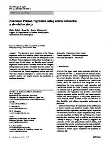
The main benefit of networks with this architecture is that they are universal approximators, [23]. Fig 14 is taken from [37], and it illustrates a typical result based on an application to an advanced guided missile concept. Shown in this figure is a comparison of responses to a 90o AoA command using the multi-layer NN described above, with both a more conventionally designed gain scheduled controller and an adaptive controller employing a singlelayer NN. The gain scheduled linear controller (provided by Boeing Phantom Works) makes use of all the aerodynamic data, and a 3 dimensional gain schedule on altitude, mach and AoA. The adaptive design uses only linearized aerodynamics at a single flight condition. Note that while the single-layer NN provides performance similar to that of the adaptive controller, the multilayer NN is much better able to capture all the nonlinearities, and provide an essentially linear third order response characteristic, which is the ideal response for which the design was performed. 100
90
80
70
alpha (deg)
60
50
40
30 command
20
multi−layer single−layer 10
0
gain schedule
0
0.2
0.4
0.6
0.8
1 t (sec)
1.2
1.4
1.6
1.8
2
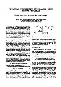
Fig.14. Angle-of-attack step responses for several missile autopilot designs.. Another important issue concerns robustness of adaptive systems to unmodeled dynamics. The problem of robust control of nonlinear systems with input unmodeled dynamics has been treated in [12] using the concept of nonlinear dynamic damping. In this formulation, the system is taken as linear in the control. In [35], we have extended this concept to the problem of robust control of adaptive systems. Moreover, we have removed the restriction that the dynamics be linear in the control. However, the results are valid only for linearly parameterized networks. Fig’s 15 and 16 illustrate the benefit of incorporating nonlinear dynamic damping as a part of the network learning algorithm. Shown is a comparison of responses to filtered square wave commands for a simple pitch plane model that includes unmodeled first order actuator dynamics represented by a time constant (τ). The nominal response corresponds to using the network learning algorithm of [32], the robustified response employs the learning algorithm of [35]. Note that the nominal response is unstable for τ = 0.03 , while the robustified response remains stable for τ = 01 . . Furthermore, the response is indistinguishable from responses at smaller values of τ.
17
Future research will be focused on deriving learning algorithms for nonlinearly parameterized networks in the presence of a class of unmodeled dynamics present at the plant input. One approach is to combine dynamic nonlinear damping development of [35] with the multi-layer NN development of [37]. While this may provide a solution from a theoretical perspective, it may be overly conservative to be of practical usefulness. This is because in each solution approach, additional terms are introduced to account separately for nonlinear parameterization and unmodeled dynamics. A more unified approach will be pursued that can simultaneously account for these effects, and thereby lead to learning algorithms with less conservative restrictions that need to be satisfied to guarantee global stability. 15
15 command
command
tau = 0.01 tau = 0.03
10
5
alpha (deg)
alpha (deg)
5
0
0
−5
−5
−10
−10
−15
tau = 0.03 tau = 0.1
10
0
5
10
−15
15
0
5
t (sec)
10
15
t (sec)
Fig.15. Nominal angle-of-attack response.
Fig.16. Robustified angle-of-attack response.
Future Technology Transition There are numerous opportunities envisioned for transitioning NN technology to applications within the aerospace industry, besides the tiltrotor application described in a previous section. The potential payoffs in aircraft applications include: • reduced flight control system design/development costs, • reduced costs associated with the need to develop a large aerodynamic data base, • reduction of control related accidents, and • maintenance of handling qualities immediately following failures and battle damage. Payoffs in missile and guided munition applications include several of the above mentioned factors, and in addition: • robustness to uncertain high AoA aerodynamics (such as the ‘phantom yaw’ effects), • robustness to CG shifts and uncertain mass properties, • accommodation of variants within a class of munitions with a single control design, • improved and more predictable weapon performance, and • the potential for eliminating the need for wind-tunnel testing.
18
Aircraft Flight Control The NN based adaptive controller, as it presently exists, is undergoing an extensive evaluation within an Air Force program known as RESTORE. The objective of this program is to investigate alternative approaches for designing reconfigurable flight control systems for tailless fighter aircraft. To date, the NN based approach has demonstrated that handling qualities can be maintained for a variety of failure modes. Boeing is currently pursuing a path to transition the RESTORE work to the X-36, Fig 17, for future flight testing. As a result of the success thus far on the RESTORE program, Boeing has initiated a new program called Robust Adaptive Controller Experiment (RACE). Its goal is to develop a NN-controller for all Boeing products (aircraft, rotorcraft, missiles, munitions). The immediate application opportunities identified in the aircraft area include the F-18, the C-17, and unmanned aerial vehicles.
Fig.17. X-36 vehicle proposed for near-term technology demonstration.
Fig.18. F-18 System Research Aircraft proposed for future upgrades, including damage adaptive flight control.
Transition opportunities to several programs exist, such as the planned F-18E/F upgrades, Fig 18, and the ‘Integrated Data Acquisition and Control System’ (IDACS) follow-on initiatives proposed in the area of improved flight safety using the Boeing C-17 aircraft. The currently envisioned F-18E/F roadmap has identified new technologies such as damage adaptive flight/propulsion controls, with a flight demonstration program in FY-01. The goal of the IDACS program is to prevent accidents due to unexpected failures or damage that may affect aircraft control, stability and safety. One approach entails developing and demonstrating emergency backup systems that enable damage tolerant and fault transparent flight control. One approach to achieve such a system is to do on-line system identification on the damaged aircraft, followed by on-line redesign of the flight control system. This is the basic approach currently being developed under this program. Our approach would eliminate the need for system identification for purposes of control system redesign. Instead, the flight control system would directly adapt to the failed condition, and fault identification would only be needed for on-line effector management. In this setting, identification can be accomplished on a longer time scale for optimal management of the control distribution, while the adaptive system maintains stability and reasonable pilot handling qualities. A longer-term transition opportunity
19
is NASA’s X-33 program, which has the requirement for operational flight safety in the presence of a single actuator failure during a mission. Guided Missiles and Guided Munitions An area of particular concern in high AoA flight is vortex shedding that leads to the socalled ’phantom yaw’ effect. The passive means proposed for mitigating this problem entail changes to the nose cone shape that may interfere with or compromise the seeker’s ability to track the target during the homing phase of missile guidance. Therefore, one of the major recommendations from a recent High Alpha workshop at Eglin AFB is that active means that employ either synthetic blowing at the nose tip, or other applicable micro-electro-mechanicalsystems (MEMS) technology be investigated to control vortex shedding. Such controllers exhibit highly nonlinear characteristics, particularly with respect to the control action. In addition, it is very difficult to accurately model these effects. Therefore, highly adaptive, nonlinear control is viewed as an enabling technology for MEMS, particularly in the area of control of external flows. This will likely require extension of current research into the areas of output feedback adaptive control of uncertain dynamic systems.
Conclusions The effectiveness of a controller architecture, which combines adaptive feedforward neural networks with feedback linearization, has been demonstrated on a variety of flight vehicles. The boundedness of tracking error and control signals is guaranteed. The architecture can accommodate both linear-in-the-parameters networks, as well as single-hidden-layer perceptron neural networks. Both theoretical and experimental research is planned to expand and improve the applicability of the approach, and to demonstrate practical utility in the areas of cost reduction and improved flight safety.
Acknowledgment The authors thank Bill Decker at the NASA Ames Research Center for his support, which included unpublished material on the civilian tilt-rotor project. This research supported by ARO, AFWL, AFOSR, and NASA. The authors gratefully acknowledge the feedback received from anonymous reviewers.
Appendix Proof of Theorem: Consider the candidate Lyapunov function ~ ~ L(e, W) = e T Pe + W T
−1
~ W = ζ T P ′ζ
For K P > 0 and K D > 0 , A is Hurwitz, and for all Q = Q T > 0 the solution of
20
(A.1)
A T P + PA = − Q
(A.2)
is P = P T > 0 . For Q = I 2 this implies Eqn 18. Differentiating Eqn A.1, substituting Eqn 16, and using Eqn A.2, gives
{
~ ) + 2 W T e T Pb +
L& = −e T Qe + 2 e T Pb(W *T −
−1
~& W
}
(A.3)
Substituting Eqn 17 reduces Eqn A.3 to L& = − e T Qe + 2 e T Pb(W *T − ≤
− e +2 2
*
)
T
e Pb
(A.4)
Using e T Pe ≤ (P) e
2
(A.5)
it follows that e T Pe L& ≤ − +2 (P)
*
e T Pe
(P)
(A.6)
which is strictly negative when e T Pe > 2
Then
α
*
(P)
2
(A.7)
⊂ B is a positively invariant set of Eqn 16. Furthermore, define r
{
Ω β = ζ ∈ B r : e T Pe ≤ 4 If Ω ⊂
3
α
*2
(P) 3
}
(A.8)
, this requires that
4 *2 (P) 3 < α Then the minimum size of B r can be quantified by 4 *2 (P) 3 r2 > λ (P ′) and ' must be sufficiently large, so that Br ⊂ ' .
(A.9)
(A.10)
~ This is sufficient to show, via the LaSalle-Yoshizawa theorem [11], that e(t ) and W(t)
remain bounded. Furthermore, if ∆* ≡ 0 , (no NN approximation error) then Ω reduces to the
v
origin and lim e(t ) = 0 . t →∞
References [1] K.A.Wise and D.J.Broy, “Agile Missile Dynamics and Control,” AIAA 96-3912, AIAA Guidance, Navigation and Control Conference, 1996. [2] A.Isidori, Nonlinear Control Systems, Springer-Verlag, Berlin, 1989. 21
[3] G.Meyer and L.Cicolani, “Application of Nonlinear Systems Inverses to Automatic Flight Control Design System Concepts and Flight Evaluations,” AGARDograph AG-251 on Theory and Applications of Optimal Control in Aerospace Systems, NATO, pp. 10-1 to 10-29, 1980.
[4] P.K.A.Menon, G.B.Chatterji and V.H.L.Cheng, “A Two-Time-Scale Autopilot for High Performance Aircraft,” Proceedings of the AIAA Guidance, Navigation, and Control Conference, 1991.
[5] D.J.Bugajski, D.F.Enns and M.R.Elgersma, “A Dynamic Inversion Based Control Law With Application to the High Angle of Attack Research Vehicle,” Proceedings of the AIAA Guidance, Navigation, and Control Conference, pp. 20-22, 1990.
[6] S.A.Snell, D.F.Enns and W.L.Garrard, “Nonlinear Inversion Flight Control for a Supermaneuverable Aircraft,” AIAA Journal of Guidance, Control, and Dynamics, Vol. 15, No. 4, pp. 976-984, 1992.
[7] J.MBuffington, A.G.Sparks and S.S.Banda, “Full Conventional Envelope Longitudinal Axis Flight Control with Thrust Vectoring,” Proceedings of the American Control Conference, pp. 415-419, 1993.
[8] J.S.Brinker and K.A.Wise., “Stability and Flying Qualities Robustness of a Dynamic Inversion Aircraft Control Law,” AIAA Journal of Guidance, Control, and Dynamics, Vol. 19, No. 6, pp. 1270-1277, 1996.
[9] R.J.Adams and S.S.Banda, “An Integrated Approach to Flight Control Design Using Dynamic Inversion and µ-Synthesis,” Proceedings of the American Control Conference, pp. 1385-1389, 1993.
[10] J.M.Buffington, R.J.Adams and S.S.Banda, “Robust Nonlinear High Angle of Attack Control Design for a Supermaneuverable Vehicle,” Proceedings of the AIAA Guidance, Navigation, and Control Conference, pp. 690-700, 1993.
[11] M.Krstic, I.Kanellakopoulos and P.V.Kokotovic, Nonlinear and Adaptive Control Design, John Wiley & Sons, Inc., New York, 1995.
[12] M.Krstic, J.Sun and P.V.Kokotovic, “Control of Feedback Linearizable Systems with Input Unmodeled Dynamics,” Proceedings of the 33rd Conference on Decision and Control, pp. 16331638, 1994.
[13] P.V.Kokotovic, “The Joy of Feedback: Nonlinear and Adaptive,” IEEE Control Systems, Vol. 12, No. 3, pp. 7-17, 1992.
[14] H.Khalil, Nonlinear Systems, Macmillan Publishing Company, New York, 1992. [15] Narendra, et-al., IEEE Transactions on Automatic Control, Vol. 25, pp. 433-461, 1980. [16] S.S.Sastry and A.Isidori, “Adaptive Control of Linearizable Systems,” IEEE Transactions on Automatic Control, Vol. 34, No. 11, pp. 1123-1131, 1989.
22
[17] I.Kanellakopolous, P.V.Kokotovic and A.S.Morse, “Systematic Design of Adaptive Controllers for Feedback Linearizable Systems,” IEEE Transactions on Automatic Control, Vol. 36, No. 11, pp. 1241-1253, 1991.
[18] B.B.Peterson and K.S.Narendra, “Bounded Error Adaptive Control,” IEEE Transactions on Automatic Control, Vol. 27, No. 6, pp. 1162-1168, 1982.
[19] S.M.Naik, P.R.Kumar and B.E.Ydstie, “Robust Continuous-Time Adaptive Control by Parameter Projection,” IEEE Transactions on Automatic Control, Vol. 37, No. 2, pp. 182-197, 1992.
[20] Y.Zhang and P.A.Ioannou, “Stability and Performance of Nonlinear Robust Adaptive Control,” Proceedings of the 34th Conference on Decision and Control, pp. 3941-3946, 1995.
[21] S.Golpaswamy and J.K.Hedrick, “Robust Adaptive Nonlinear Control of High Performance Aircraft,” Proceedings of the American Control Conference, pp. 1279-1283, 1990.
[22] P.V.Kokotovic and R.A.Freeman, “Robust Integral Control for a Class of Uncertain Nonlinear Systems,” Proceedings of the 34th Conference on Decision and Control, pp. 2245-2250, 1995.
[23] K.Hornik, M.Stinchombe and H.White, “Multilayer Feedforward Networks are Universal Approximators,” Neural Networks, Vol. 2, No. 5, pp. 359-366, 1989.
[24] R.M.Sanner and J.E.Slotine, “Gaussian Networks for Direct Adaptive Control,” IEEE Transactions on Neural Networks, Vol. 3, No. 6, pp. 837-863, 1992.
[25] R.L.Barron et al., “Applications of Polynomial Neural Networks to FDIE and Reconfigurable Flight Control,” Proceedings of the IEEE National Aerospace and Electronics Conference, pp. 507-519, 1990.
[26] D.J.Linse and R.F.Stengel, “Identification of Aerodynamic Coefficients Using Computational Neural Networks,” Proceedings of the AIAA Aerospace Design Conference, Irvine, CA, 1992.
[27] W.L.Baker and J.A.Farrell, “Learning Augmented Flight Control for High Performance Aircraft,” Proceedings of the AIAA Guidance, Navigation, and Control Conference, pp. 347-358, 1991.
[28] J.E.Steck and K.Rokhasz, “Use of Neural Networks in Control of High Alpha Maneuvers,” 30th AIAA Aerospace Sciences Meeting and Exhibit, Reno, NV, 1992.
[29] P.J.Werbos, “Neural Networks and Flight Control: Overview of Capabilities and Emerging Applications,” Proceedings of the AIAA Guidance, Navigation, and Control Conference, pp. 912919, 1995.
[30] M.Steinberg, “Potential Role of Neural Networks and Fuzzy Logic in Flight Control Design and Development,” Proceedings of the AIAA Aerospace Design Conference, Irvine, CA, 1992.
[31] M.Steinberg, “An Initial Assessment of Neural Network and Fuzzy Logic Technology for Flight Control Systems,” Proceedings of the American Control Conference, pp. 173-177, 1994.
23
[32] B.S.Kim and A.J.Calise, “Nonlinear Flight Control Using Neural Networks,” AIAA Journal of Guidance, Control, and Dynamics, Vol. 20, No. 1, pp. 26-33, 1997.
[33] A.J.Calise, S.Lee and M.Sharma, “Direct Adaptive Reconfigurable Control of a Tailless Fighter Aircraft”, to be presented at the AIAA Guidance, Navigation, and Control Conference, Boston, MA, August, 1998. [34] M.B.McFarland and A.J.Calise, “Nonlinear Adaptive Control of Agile Anti-Air Missiles Using Neural Networks”, AIAA Missile Sciences Conference, Monterey, California, December, 1996. [35] M.McFarland and A.J.Calise, “Robust Adaptive Control of Nonlinear Systems Using Neural Networks”, American Control Conference, Albuquerque, NM, June, 1997. [36] A.J.Calise and M.Sharma, “An Adaptive Autopilot Design for Guided Munitions”, to be presented at the AIAA Guidance, Navigation, and Control Conference, Boston, MA, August, 1998.
[37] M.B.McFarland and A.J.Calise, “Multilayer Neural Networks and Adaptive Nonlinear Control of Agile Anti-Air Missiles”, AIAA 97-3540, AIAA Guidance, Navigation, and Control Conference, 1997.
[38] J.Leitner, A.J.Calise and J.V.R.Prasad, “Analysis of Adaptive Neural Networks for Helicopter Flight Controls,” AIAA Journal of Guidance, Control, and Dynamics, Vol. 20, No. 5, Sept.-Oct., pp.972-979, 1997.
[39] T.Jiang, J.V.R.Prasad and A.J.Calise, "Adaptive Fuzzy Logic Flight Controller for Rotorcraft," AIAA 96-35729, AIAA Guidance, Navigation, and Control Conference, 1996.
[40] R.T.Rysdyk and A.J.Calise, “Adaptive Model Inversion Flight Control for Tiltrotor Aircraft”, submitted to AIAA Journal of Guidance, Control, and Dynamics.
[41] R.T.Rysdyk, A.J.Calise and R.T.N.Chen, “Nonlinear Adaptive Control Of Tiltrotor Aircraft Using Neural Networks”, AIAA/SAE World Aviation Congress 1997 proceedings, Anaheim, CA, October 1997.
[42] Aeronautical Design Standard, “Handling Qualities Requirements for Military Rotorcraft”, ADS-33D, U.S.Army, St. Louis, MO, July 1994.
[43] W.A.Decker, “Piloted Simulator Investigations of a Civil Tiltrotor Aircraft on Steep Instrument th Approaches,” AHS 48 Annual Forum, Washington, D.C., June 1992.
[44] NASA CR-166536, A Mathematical Model for Real Time Flight Simulation of a Generic Tilt-Rotor Aircraft, Sept. 1988, Rev. A [45] B.Etkin, Dynamics of Atmospheric Flight, John Wiley & Sons, New York, 1972. [46] K.S.Narendra and A.M.Annaswamy, “A New Adaptive Law for Robust Adaptation Without Persistent Excitation,” IEEE Transactions on Automatic Control, Vol. 32, No. 2, pp. 134145, 1987.