On the automatic generation of timed automata models from ISA 5.2 diagrams Luiz Paulo de Assis Barbosa, Kyller Gorgˆonio, Antonio Marcus Nogueira Lima, Angelo Perkusich Federal University of Campina Grande Embedded Systems and Pervasive Computing Lab. Campina Grande, Para´ıba, Brazil {luizpaulo,kyller,amnlima,perkusic}@dee.ufcg.edu.br Leandro Dias da Silva Para´ıba State University Mathematics, Statistics and Computation Department Campina Grande, Para´ıba, Brazil
[email protected]
Abstract Safety Instrumented Systems (SIS) are usually designed to prevent accidents, avoid undesirable situations and guarantee continuous operation of oil and gas production systems. An interruption in the operation can be caused by faults in sensors and/or actuators. Hence, SIS are usually integrated to the supervisory control system in order to use the information from sensors to prevent such undesirable situations. In this scenario, it is important to be able to validate the SIS implementation against its specification in order to increase the reliability of the system. In this work a technique to improve the dependability of SIS is introduced. A method to obtain a timed automata from a ISA 5.2 specification is presented and applied to a case study provided by Petrobras (Brazilian oil company). Finally, an approach to perform automatic testing of the implementation using the generated model is discussed. The method introduced here is based on the use of the Uppaal model checker and the Uppaal-TRON testing tool.
1. Introduction In the context of oil and gas operation it is necessary to use safety systems to prevent accidents and undesirable situations. The continuous operation of such systems is essential to prevent accidents without interrupting the production line. The operation interruption can be caused by sensors and actuators fault, safety logic executors or it can be related to errors in the execution logic. Moreover, under some situations the developed system can behave in an inadequate way due to system components dimensioning errors. Safety Instrumented Systems (SIS) [7, 8] are important
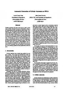
in the operation of oil and gas plants when executing automatic procedures or under the intervention of human operators. These systems are usually integrated to the supervisory control system and use the information collected from sensors and, based on the process state, they use field devices to prevent undesirable situations. In Figure 1 the development scenario for SIS is illustrated. Firstly the company generates a set of requirements that is given in form of cause/effect matrices and some additional text explaining things not present in the table. Then a third part software company produces the ISA 5.2 binary logic diagrams [12] from the matrices to conclude the specification. Once the specification is completed, the SIS can be developed using some of the IEC 61131-3 language [13], this is also done by a third part company. Finally, the IEC program is compiled to run in a certain Programmable Logic Controller (PLC). Observe that the oil company has no formal guarantee that the final implementation corresponds to its original specification. Even considering the fact that there is an important phase of acceptance tests, the main guarantee that the code running in the PLC implements correctly the specification is the trust in the companies developing intermediary artifacts. Considering this scenario it is important to make use of tools to validate the safety logic in operation or being developed. For example, it is interesting to dispose of testing tools for that are able to automatically test if the control system running behaves as expected. In this work a technique to improve the dependability of SIS is presented. The technique is based on the use of timed automata [1] and a conformance testing tool for timed automata in order to improve the quality of control programs running on PLCs. The approach consists in the generation of timed automata model from the logic
Figure 1. PLC development process diagrams in order to test its behavior against a real implementation. To achieve this, some tools are used:
programs is presented, and a method to translate a PLC controller into a PN model is described. The automated verification of Ladder Diagrams (LD) is proposed in [19]. The control programs are translated into finite automata that can be verified sing the SMV model checker [16]. Translation of LD programs in PNs is also discussed in [9] with LD operators modeled by a PN structure and the control specification is simulated with the PN. In [17] safety and operability properties of PLCs are verified. The method consists of a system model, assertions, and a model checker that verifies if the system model satisfies the assertions. In [2], Function Block Diagrams (FBD) are modeled as High Level Timed Petri nets (HLTPN) [6] by a set of tools called PLCTOOLS. It uses differential equations for modeling the plant, FBDs for designing the controller and HLTPN to validate the design and generate the source code. A more detailed discussion about verification of control programs can be found in [20]. Unlike the related work discussed above, this paper is not focused on the formal verification of control programs. The main motivation of the current work is to be able to perform automatic test of a control program. More specifically, the goal is to test a given control program implementation is correct with respect to its specification. The specification, which is described by binary logic diagrams according to the ISA 5.2 [12] document, is automatically translated into a timed automata model that is described using Uppaal [3]. Then, Uppaal-TRON [14] is used to test if the execution traces of the implementation are in conformance with the traces of the specification model.
1. Uppaal [3] for edition, simulation and verification 2. Uppaal-TRON [14] for automatic test cases generation and execution 3. An automatic generator of timed automata models from ISA 5.2 specifications developed by the authors 4. A TRON adapter to test a model against another model also developed by the authors The paper focus on the generation of such timed automata model and a case study provided by the Brazilian oil company (Petrobras) was used to validate our technique. Additionally, some tools to automate this process were developed. The rest of the paper is organized as follows. In Section 2 related work is discussed. In Section 3 the testing technique introduced here is presented in more details. Section 4 describes the timed automata generation procedure. Finally, the conclusions and future works are discussed in Section 5 .
2. Related work This section introduces existing approaches for modeling control programs described using the IEC 611313 languages. These approaches includes methods for the verification of control programs described in: 1. Instruction list
3. Methodology
2. Ladder diagrams
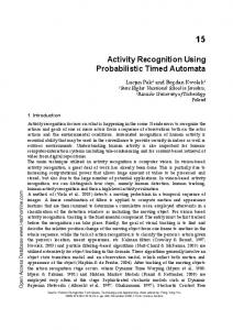
This work is bounded by the scenario illustrated in Figure 1, in which the development process of SIS is introduced. In other words, the scope of our work is to improve the dependability of the final product without interfering in the process itself. As stated before, the main goal is to guarantee that the control program running in a PLC behaves as specified. This scenario is illustrated in Figure 2. The inputs for the technique are the specification of the control program, its implementation and a description of the execu-
3. Function block diagrams In [4] programs written in Instructions List (IL) are translated into a communication automata that can be formally verified. The formal semantics for a subset of the IL language is proposed and a direct coding of this semantics into a model checking tool and behavioral properties are described in LTL. In [15] IL programs are modeled as timed automata but only Boolean variables are considered. Also, in [10] a Petri net (PN) [18] semantics for IL 2
Figure 2. Methodology tion environment. Firstly, a timed automata is extracted from the specification. Secondly, another timed automata is extracted from the PLC program. Observe that in the generation of the timed models, the description of the environment should be considered. At the moment we consider the environment to be more permissive as possible, i.e. each input variable can assume any Boolean value non-deterministically. Note that in Figure 2 the original development process is preserved. The actions indicated by the gray arcs are in accordance with the scenario defined in Figure 1 and the development of the control program is done as usual. The actions of the testing methodology introduced here are indicated by the black arcs. Specifically, the generation of timed automata model for ISA 5.2 diagrams and IEC 61131-3 programs are illustrated. Also, the test of the control program against its specification is highlighted. The automata generation has an intermediary step that is the translation of the inputs to an XML representation. By using the XML representation the technique is platform independent. It is only necessary to export the input diagrams for the correct XML schema. In the best case, in which different manufacturers have their own implementation of a certain language (e.g. Ladder), it is only necessary to implement the translation from the language to the XML. In the worst case, in which is necessary to support another language, it is also needed to implement a new timed automata generator. In this work, the input is given by an ISA 5.2 specification and some IEC 61131-3 implementation. They were chosen due to the fact that they are the languages used at Petrobras. However, the methodology is designed to be easily extended. After obtaining the timed automata models, the testing tool TRON is used to validate the Implementation Un-
der Test (IUT) against the specification. More specifically, TRON is used to generate a set of traces using the specification automata that are used to test the IUT automata. Each trace is formed by a sequence of input and output events. Each input event in the trace generates an event to the IUT in order to observe its response for a given stimuli. If the output from the IUT is in conformance with the output from the specification then the test was successful. Otherwise, the test fails. Another possibility that needs to be explored is to directly test the implementation through the use of OLE for Process Control (OPC). Directly testing the PLC has the advantage that no errors were introduced during the transformation step. Moreover, sometimes engineers modify the machine code running into the PLC without modifying the original FBD or Ladder program. Hence, the only possible way to test the PLC against the specification is through OPC. However, in this case it is not possible to use logical time. Instead, real-time should be used and the tests will take much more time to conclude. 3.1. Uppaal and TRON Timed automata [1, 11] are finite state machines extended with clock variables. Uppaal [3] is an environment for edition, simulation and verification of real-time systems modeled as a timed automata. In Uppaal a model is given by a network of timed automata that is obtained by combining one or more timed automata together. A state is defined according the localities, the clock restrictions and the values of discrete variables, and every time an action is executed, a new state is reached. In the network, each automata can be executed alone or synchronized with another automata. Such synchronization occurs through the use of communication channels in which of automata writes on the channel at the same time 3
the another reads from it. Broadcast channels are also allowed. Verification is done using its own model checker, and sub-set of the CTL temporal logic [5] used as specification language. Uppaal-TRON [14], or simply TRON, is a Uppaalbased tool used to perform conformance tests in timed system. Test cases are generated and executed at the same time event by event. TRON works as a replacement of the environment of an IUT by generating events and monitoring. The idea is that for a certain input, the IUT should react as the specification. TRON provides an Application Program Interface (API) to allow communication between Uppaal timed models and IUT, remember that the IUT can be a real implementation. In this way, the developer needs to write an adapter to communicate both artifacts using such API. This is what makes possible to connect physical events of the IUT with logical events of the timed automata. Adapters can be build using UNIX standard I/O mechanisms or TCP/IP sockets. Also, GNU C and Microsoft Visual C APIs are available.
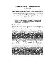
general shutdown occurs (SD-GENERAL==true) or when manually started (HS==true). Both conditions switches the output of the SR flip-flop to true, indicating that the process of purge is in progress. If the purge process is not interrupted, then it will finish after time T1. Signals PURGE PERMISSION, SD-PURGE and IGNITION PERMISSION are used to avoid the beginning of purge in a inadequate moment, to allow the purge to be interrupted at any moment and to indicate its termination, respectively. These signals act on the reset input of the SR flip-flop. If purge is concluded and the HEADER signal exists then the ignition permission is enabled. This permission can be kept valid for a time T2 or it can be interrupted at any moment by signal SD-PURGE. Observe that some signals are connected to other diagrams which are not displayed here. In a PLC program the input is frozen in the beginning of a scan cycle. All input variables are read and in the end of the cycle all outputs are generated. In other words changes on the input are only perceived by the PLC in the beginning of the cycle, and output changes are passed to the environment only at the end of the scan cycle.
4 From ISA 5.2 to timed automata
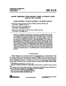
Waiting
ISA 5.2 is a standard that provides symbols for standard PLC functional blocks. The main symbols are the logic AND, OR and NOT operators, SR flip-flop with set or reset priority, and time elements. The time elements are Delay Initialization of output (DI), Delay Termination of output (DT) and Pulse Output (PO). The operation of the basic logic functions are trivial and not explained here. The SR flip-flop output exists if S exists and do not exists if R exists. The priority in S or R defines the output regardless the value of the other input. The DI output exists if the input exists for at least a given interval of time t and terminates when the input terminates. The DT output exists immediately when the input exists and terminates when the input has terminated and has not again existed for time t. The output of PO exists immediately when the input exists and terminates after time t. A typical specification of a control system is illustrated on Figure 3. The common elements used on binary logic diagrams can be identified: OR, AND, SR flip-flop, DI (and respective time delay given by T1 and T2), inputs (HS), outputs (XA) and logical connectors to other diagrams of the same control program (HEADER, SDGENERAL, etc.). In the generation method defined in this work each SR flip-flop and each temporized component of the diagram (DIs, POs, DTs, etc.) are modeled as a timed automata. The logical entities (OR, AND) are modeled as guards of the timed automata of the flip-flops and temporized components. The binary logic diagram of Figure 3 models the logical sequence to accomplish the purge and activation of the signal IGNITION PERMISSION for a certain type of industrial heater. The purge is accomplished always that a
update!
read_input()
t=0, CN=false, write_output() CN==false
synchro! CN=control() Executing
CN==false && t