IEEE TRANSACTIONS ON VISUALIZATION AND COMPUTER GRAPHICS, VOL. 12, NO. 5, SEPTEMBER/OCTOBER 2006
Exploded Views for Volume Data ¨ Stefan Bruckner and M. Eduard Groller, Member, IEEE Computer Society Abstract—Exploded views are an illustration technique where an object is partitioned into several segments. These segments are displaced to reveal otherwise hidden detail. In this paper we apply the concept of exploded views to volumetric data in order to solve the general problem of occlusion. In many cases an object of interest is occluded by other structures. While transparency or cutaways can be used to reveal a focus object, these techniques remove parts of the context information. Exploded views, on the other hand, do not suffer from this drawback. Our approach employs a force-based model: the volume is divided into a part configuration controlled by a number of forces and constraints. The focus object exerts an explosion force causing the parts to arrange according to the given constraints. We show that this novel and flexible approach allows for a wide variety of explosion-based visualizations including view-dependent explosions. Furthermore, we present a high-quality GPU-based volume ray casting algorithm for exploded views which allows rendering and interaction at several frames per second. Index Terms—Illustrative visualization, exploded views, volume rendering.
✦ 1
I NTRODUCTION
Occlusion is an important problem when rendering truly threedimensional information in scientific visualization, such as, for example, medical data acquired from computer tomography. Because of occlusion, normally not all of the data can be shown concurrently. Frequently, the user wants to examine an object of interest within the volumetric data set. In many cases depicting this focus object on its own is not sufficient – the user is interested in exploring it within the context of the whole data set. To solve the problem of occlusion the context can be assigned a different - more sparse - visual representation, for example by reducing its opacity. This adjustment can even be performed locally, so the representation only changes for those parts of the context which actually occlude the focus [32, 33, 2]. In illustrations, cutaways and ghosting techniques are used for this purpose. However, the drawback of these approaches is that parts of the context information are still removed or suppressed. If it is instructive to retain the context even when it occludes the focus structure, illustrators often employ exploded views. Basically, in an exploded view the object is decomposed into several parts which are displaced so that internal details are visible (see Figure 1). This does not only give an unobstructed view on the focus but also potentially reveals other interesting information, such as cross-sections of the split object. The advantage of exploded views is that they simultaneously convey the global structure of the depicted object, the details of individual components, and the local relationships among them. The contribution of this paper is a new technique for generating exploded views based on a three-dimensional force-directed layout. We present an approach that is capable of producing high quality exploded depictions of volume data at interactive frame rates. One application of our framework is the generation of highly detailed anatomic illustrations from scanned data (see Figure 2 and Figure 3). The paper is structured as follows: In Section 2 we discuss related work. Section 3 presents our approach for the generation of exploded views from volumetric data sets. In Section 4 we detail our rendering algorithm. The paper is concluded in Section 5.
• Stefan Bruckner and M. Eduard Gr¨oller are with the Institute of Computer Graphics and Algorithms, Vienna University of Technology, E-mail: {bruckner|groeller}@cg.tuwien.ac.at. Manuscript received 1 March 2006; accepted 1 August 2006; posted online 6 November 2006. For information on obtaining reprints of this article, please send e-mail to:
[email protected].
Fig. 1. An early example of exploded views by Leonardo da Vinci – also note the smaller depictions which show the use of different explosion setups (”The babe in the womb”, c.1511).
2
R ELATED W ORK
The concept of cutting away parts of the volume to reveal internal structures is quite common in volume visualization. Nearly every volume renderer features simple clipping operations. Wang et al. [34] introduce volume sculpting as a flexible approach for exploring volume data. The work of Weiskopf et al. [35] focuses on interactive clipping operations using arbitrary geometry to overcome the limitations of common clipping planes. Konrad-Verse et al. [22] use a deformable cutting plane for virtual resection. The work of Dietrich et al. [10] consists of clipping tools for the examination of medical volume data. Owada et al. [26, 27] present a system for modeling and illustrating volumetric objects using artificial cutting textures based
IEEE TRANSACTIONS ON VISUALIZATION AND COMPUTER GRAPHICS, VOL. 12, NO. 5, SEPTEMBER/OCTOBER 2006
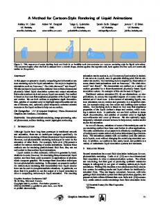
Fig. 2. Interactive exploded-view illustration of a human head with increasing degrees-of-explosion. Two hinge joints are used to constrain part movement.
(a)
Exploded views have been investigated in the context of architectural visualization by Niedauer et al. [25]. Finally, McGuffin et al. [24] were the first to thoroughly investigate the use of exploded views for volume visualization. Their approach features several widgets for the interactive browsing of volume data partitioned into several layers. The difference to our work is that our approach employs a force-directed placement algorithm to automatically arrange the parts of an exploded view in order to reveal a focus object. Additionally, while McGuffin et al. only employ simple cuberille rendering [19], we present a high-quality GPU-based direct volume rendering algorithm. As one of the main contributions of this paper we present an approach for the automated generation of exploded views from volume data which does not rely on extensive object information. The technique distinguishes between focus and context using a fuzzy degreeof-interest function. Rather than manually specifying a transformation for each part of the context, the paper discusses an automatic technique which produces a three-dimensional layout of the parts. Our approach is also capable of re-arranging the parts dynamically based on the viewpoint. We further employ a simple interaction metaphor for specifying part geometry. Finally, the paper describes a high-quality GPU-based volume ray casting approach for the rendering of exploded views at interactive frame rates. 3
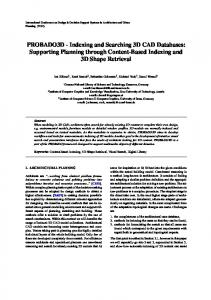
(b) Fig. 3. (a) Plastinated anatomic model in Gunther von Hangens’ ”Bodyworlds” exhibition (image courtesy of http://www.bodyworlds.com). (b) Interactive exploded-view illustration generated with our framework.
on surface models. Chen et al. [7] introduced the concept of spatial transfer functions as a theoretical foundation for modeling deformations in volumetric data sets. Islam et al. [20] extend this work by using discontinuities (i.e., splitting of the volume). Some approaches employ a curve-skeleton [8]. The curve-skeleton is a reduced representation of a volumetric object which can be generated using techniques such as volume thinning [14]. Gagvani et al. [15] animate volume data sets using a skeleton-based approach. The interactive system presented by Singh et al. [30] allows manual editing of volume deformations based on a skeleton. They extend this work by introducing selective rendering of components for improved visualization [29]. Correa et al. [9] use traversal of the skeleton tree to illustrate properties such as blood flow.
G ENERATING E XPLODED V IEWS
FROM
VOLUME DATA
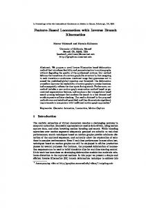
Our approach distinguishes between two basic objects derived from the volumetric data set. The selection (see Figure 4a) is the current focus object specified by a selection volume. The selection volume defines a real-valued degree-of-interest function [11]. A sample of the selection volume at a specific position indicates the degree-of-interest for the corresponding data sample, where one means most interesting and zero means least interesting. The selection object comprises all data samples with non-zero degree-of-interest. The advantage of this definition is that it allows a smooth transition between focus and context. Everything that is not selected is part of the background (see Figure 4b) which represents the context. Segments of the background object undergo a transformation while the selection remains static. We divide the space covered by the background into an arbitrary number of non-intersecting parts Pi (see Figure 4c). Each part is defined by its geometry and its transformation. For simplicity, we introduce the restriction that each part is convex – concave objects can be formed by grouping together several convex parts. In general, the geometry of a part does not correspond to the shape of the actual object contained in the part (which is determined by the selection volume, the data volume, and the specified transfer function). It merely bounds the space that can be occupied by this object. It is therefore sufficient to represent the part geometry by a bounding polygonal mesh. Using this setup we can generate exploded views where the parts are moved away to reveal the selection. However, it can be very tedious and time-consuming to manually specify the transformation for each
BRUCKNER et al.: EXPLODED VIEWS FOR VOLUME DATA
(a)
(b)
(c)
Fig. 4. Object setup for exploded views. (a) selection object. (b) background object. (c) background object decomposed into parts.
part. We want a simple global mechanism to specify how ”exploded” a view should be. Therefore, we introduce a degree-of-explosion parameter. When the degree-of-explosion is zero all parts remain untransformed. By increasing the degree-of-explosion, the user can control how much of the selection is revealed. While it would be possible to use an ad-hoc method for displacing parts according to the degree-of-explosion, we choose to employ a force-based approach. In graph drawing, force-directed layout techniques model connectivity information through physical forces which can be simulated [12, 13]. Because of the underlying analogy to a physical system, force-directed layout methods tend to meet various aesthetic standards, such as efficient space filling, uniform edge lengths, and symmetry. They also have the advantage of enabling the visualization of the layout process with smooth animations. For these reasons, we control our explosion using a rigid-body physics engine [1]. Our goal is not to simulate physical reality which would require a far more sophisticated model including tissue properties, nonlinear deformation, and many other aspects. We rather want to supply the user with a simple and intuitive interface to interactively generate exploded visualizations of volumetric data sets. New types of explosions can be generated just by adding additional forces and constraints. Furthermore, the laws of Newtonian physics are generally well understood by humans which aids comprehension of the resulting motions. 3.1 Part Geometry An important step in generating an exploded view is specifying the part geometry. We provide a simple interface for rapid interactive decomposition of a volumetric data set. Our approach is based on the splitting metaphor: the user starts out with a single part which corresponds to the bounding box of the background object. By interactive splitting of this part along arbitrary planes as well as grouping and hiding parts the user can define complex part geometries with immediate feedback. Our interface provides three simple tools to split parts: Axis splitter. By clicking on a point on screen, the user splits the first part that is intersected by the corresponding viewing ray. The part is split along a plane which passes through the intersection point. Its normal is the cross product between the viewing direction and the horizontal or vertical axis of the projection plane. Depth splitter. The user clicks on a point. A viewing ray is cast which records the first intersection with the background object. The corresponding part is then split along a plane at the depth of the intersection point. The plane is parallel to the projection plane. Line splitter. The user can draw a line segment. For each part it is determined if the projection of the part intersects the line segment. All parts which intersect the line segment are split along a plane which projects to the line. As exploded views frequently employ splits based on object symmetry, these tools provide an intuitive way of specifying and refining
(a)
(b) Fig. 5. View-dependent exploded views. (a) Exploded view without viewing force – a part occludes the selection (dark blue). (b) Exploded view with viewing force – the occlusion is resolved.
part geometry. Despite the small set of operations, the concept is quite powerful as it operates in a view-dependent manner. The user can interactively rotate the volume and partition it in a natural way. In addition to this interface, our approach could straight-forwardly employ automatically defined part geometry, for example by using a precomputed curve-skeleton. 3.2 Force Configuration Force-directed layout approaches arrange elements such as the nodes of a graph by translating the layout requirements into physical forces. A simple setup uses repulsive forces between all nodes and attractive forces between nodes which are connected by an edge. A simulation is performed until the system reaches a state of minimal energy. The corresponding node positions constitute the layout. Our problem is similar. We want to arrange three-dimensional objects in such a way that they do not occlude another object, but with as little displacement as possible. Like in an atomic nucleus or a planetary system we want to achieve a steady state where the attractive forces and the repulsive forces are in equilibrium. For this reason we define a number of forces based on our requirements: Return force. This attractive force tries to move the parts towards their original location. Each vertex of the part geometry is connected with its original (i.e., untransformed) position. The force Fr is realized as a logarithmic spring: Fr = cr ln(krk) ·
r krk
(1)
where r is the vector from the vertex’s current position to its original location and cr is a constant factor. The logarithmic relationship of the force’s magnitude to the distance tends to produce less oscillation than the linear relationship of Hooke’s law. The total
IEEE TRANSACTIONS ON VISUALIZATION AND COMPUTER GRAPHICS, VOL. 12, NO. 5, SEPTEMBER/OCTOBER 2006
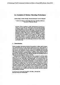
Fig. 6. Exploded view of a turtle with increasing degree-of-explosion from left to right. The body of the turtle is selected and the shell is divided into four parts.
return force for a part is normalized by dividing it by the number of vertices. Explosion force. We want to generate a force that drives the specified parts away from our selection object. The idea is to generate a force field which describes the characteristics of the selection object. Each point of the selection exerts a distance-based force on every part. In order to keep the number of points low, we use an octree-based approach. We generate two min-max octrees; one for the data volume and one for the selection volume. Each node stores the minimum and maximum data and selection values respectively, of the represented region. We traverse the two octrees simultaneously and generate an explosion point for each homogeneous octree node that contains both visible data values under the current transfer function and nonzero selection values. We add a small random bias to the position to prevent artifacts due to the regular structure of the octree. The explosion point is also weighted according to the size of the region corresponding to the octree node. Each explosion point exerts a force Fe on every part Pi : r ce Fe = krk · krk e
(2)
where r is the vector from the explosion point to the closest point of the part geometry of Pi and ce is a scaling factor. The force is applied to the closest point of the part geometry and can therefore also generate a torque. The exponential fall-off is chosen to limit the force’s influence to a region nearby the explosion point. The total explosion force is normalized by dividing it by the number of explosion points. Viewing force. So far we have only considered view-independent explosions, i.e., the movement of parts does not take into account the current viewpoint. In traditional illustration this problem typically does not occur as the viewpoint is fixed and the exploded view is specifically generated to be most appropriate for this single viewpoint. In an interactive system, however, we must consider that the user can rotate the camera arbitrarily. For this reason we introduce a view-dependent force which attempts to arrange parts so that they do not occlude the selection for the current viewing transformation. We follow the work of Carpendale et al. [5, 6] who use similar techniques for the layout of three-dimensional graphs. We project each of the explosion points to the image plane. For a part Pi we determine the point along the viewing ray corresponding to the explosion point’s projection which is closest to the center of Pi . The force Fv is then:
Fv =
r cv · krk krk
(3)
where r is the vector from the closest point along the viewing ray to the center of the body and cv is a scaling factor. The total force for a part is normalized by dividing it by the number of explosion points. Figure 5 shows an example for the influence of the viewing force. In Figure 5a the explosion force displaces the parts but disregards the viewpoint. The occlusion is resolved in Figure 5b by adding the viewing force. Spacing force. In order to prevent clustering of parts, we also add a repulsive force Fs . For a part Pi , the spacing force exerted by another part Pj is: Fs =
cs krk
2
·
r krk
(4)
where r is the vector from the center of Pj to the center of Pi and cs is a constant scaling factor. The total spacing force for a part is normalized by dividing it by the number of parts. The scaling factors of explosion force, viewing force, and spacing force, ce , cv , and cs , are scaled with the global degree-of-explosion parameter, while cr remains constant: c{e,s,v} = doe · δ{e,s,v}
(5)
where doe is the degree-of-explosion and δ{e,s,v} ∈ [0..1] specifies the relative contribution of the corresponding force. This allows the user to modify the influence of the individual forces, e.g. to reduce view dependency or to increase spacing. The algorithm is insensitive to changes in δ{e,s,v} . In our tests, a setting of δe = 12 , δv = 31 , and δs = 16 has proven to be a universally good choice. The user mostly interacts with the degree-of-explosion. Figure 6 shows a simple part configuration for different degrees-of-explosion. In addition to the basic forces discussed in this section, specific applications may employ further forces. For example, if available, connectivity information between certain parts could be modeled by additional spring forces. 3.3 Constraint Specification While the force configuration discussed in the previous section can be used to generate expressive exploded view visualizations, it is sometimes useful to constrain the movement of parts. Therefore, our approach allows the interactive addition of joints which restrict the relative movement of parts. Available joints include sliders, hinges, ball
BRUCKNER et al.: EXPLODED VIEWS FOR VOLUME DATA
Fig. 7. Exploded view using constrains to limit part movement. The skull is selected. The left part of the face is static, the remaining parts are connected by a slider joint which limits their movement to a translation along one axis.
Fig. 8. Interaction between constraints and viewing force. All parts except the two upper parts of the leg are static. These two parts are connected by hinges similar to a swing door. As the camera rotates the viewing force causes the parts to orient themselves towards the viewer.
joints, and universal joints. Additionally, the user can provide an importance for individual parts by modifying their mass. Parts with higher masses will be less affected by the individual forces and, thus, by the explosion. The user can restrict a part from being displaced by assigning an infinite mass. This is particularly useful to easily create break-away illustrations where typically only one section of the object is moved away. An example for the use of constraints is shown in Figure 2 where two hinges are used. In Figure 7 the left part of the face has been assigned infinite mass. The right part of the face is divided into several parts which are connected by a slider joint. As the degree-of-explosion is increased these parts move along the free axis to reveal the skull. By specifying constraints the user can effectively add structural information that is missing from the raw data set. It is easily possible to generate interactive illustrations which allow exploration within the constraints specified by the designer. An interesting component in this context is the viewing force. Although the movement of a part is constrained, it is still affected by the viewing force and therefore moves within the given limits to reveal the selection. An example is shown in Figure 8 where two parts are connected by a hinge joint. As the camera rotates the effect of the viewing force causes the parts to orient themselves towards the viewer. Constraining part movements may result in arrangements with partial occlusions of the selection object. Different visual representations can be employed to resolve these conflicts. Based on the viewing force that acts on a part we can modify the sparseness of the representation, for example by modifying its transparency. An example of this behavior is shown in Figure 9.
Fig. 9. Modulating transparency by the viewing force. As the two lower parts move away, their transparency reduces since the viewing force gets weaker. The upper part remains transparent because it is static – therefore the viewing force stays constant.
3.4 Selection Definition
fined once the view is exploded and will be updated interactively. As the selection and part geometry are conceptually different entities, a change in the selection object does not affect the part geometry and visa versa. It does, however, influence the explosion and viewing forces and can therefore affect the part arrangement. For instance, if regions are added to the selection which are occluded by existing parts, the viewing force will move those parts in order to provide an unconcluded view. The quality of the resulting visualization will naturally depend on how well the object of interest is segmented. Our approach is quite tolerant with respect to minor errors in the segmentation. Since we allow a non-binary definition of the selection, uncertainty in the segmentation can be represented [21]. Rendering quality for conventionally segmented objects can be improved by smoothing the binary mask.
Any segmentation algorithm can be used to define the selection. Which technique is most effective depends on the type and nature of the data set and the structure of interest. In our system we use an enhanced version of the volume painting approach presented in our previous work [3]. The user can specify the selection by painting on visible structures using a volumetric brush. This selection can be re-
4 I NTERACTIVE E XPLODED V IEW R ENDERING Fast rendering is a key requirement for an interaction-based approach like the one presented in this paper. In this section, we describe the implementation of a high-quality GPU-based ray casting algorithm for exploded views. Until recently, volume rendering on the graph-
IEEE TRANSACTIONS ON VISUALIZATION AND COMPUTER GRAPHICS, VOL. 12, NO. 5, SEPTEMBER/OCTOBER 2006
Algorithm 1 Basic rendering algorithm perform visibility sorting of the parts generate initial entry and exit points perform initial ray casting for all parts Pi in front-to-back order do generate entry and exit points for Pi (see Section 4.1) perform ray casting for Pi (see Section 4.2) end for
5 ics hardware was only possible using a multi-pass approach [23]. This has changed with the advent of conditional loops and dynamic branching in shaders. Now it is possible to implement a fragment program which completely traverses a ray [31]. Apart from the quality improvements, this allows for common acceleration techniques like early ray termination and empty-space skipping [18, 28]. For rendering an exploded view we need to be able to render a volumetric data set consisting of a background and a selection object. The background object is decomposed into several non-intersecting convex parts which can have arbitrary affine transformations. The selection object also has its assigned transformation and can intersect any part. Furthermore, we want to support empty space skipping and early ray termination. Therefore we assume that we have geometry enclosing the visible volume under the current transfer function for both background and selection object. The use of this kind of bounding structures for empty space skipping is very common in volume rendering. They are frequently based on hierarchical data structures. In our implementation, we use min-max octrees for both data volume and selection volume. Our GPU-based ray casting algorithm makes use of conditional loops and dynamic branching available in Shader Model 3.0 GPUs. It was implemented in C++ and OpenGL/GLSL. A basic overview is given in Algorithm 1. We start by performing a visibility sort of the parts. Next, we generate the entry and exit points for the segments of the selection located in front of any part and perform the ray casting step for these regions. These two steps are actually simplified cases of the general iteration steps described in Sections 4.1 and 4.2. Then we iterate through the parts in front-to-back order. For each part Pi we first establish the entry and exit points of the viewing rays for both background and selection object. Then we use this information for performing ray casting of the part. Figure 10 illustrates the algorithm. 4.1 Entry and Exit Point Generation Generally, the background entry and exit buffers always contain the entry and exit points of the viewing rays for the intersection between background bounding geometry and the part geometry. Essentially, we are using the depth buffer to perform a CSG intersection between these objects which can be simplified since the part geometry is always convex. As portions of the selection can be located in regions which are not contained in any part, the entry and exit buffers for the selection need to be generated in a slightly different way. At startup, we generate four off-screen buffers which can be bound to a texture. For this purpose, we use the recently introduced framebuffer object OpenGL extension. In these buffers we store the ray entry and exit points for both background and selection. A fragment program is bound which writes out the volume texture coordinates under the current object transformation to the red, green, and blue components and the fragment depth in viewing coordinates to the alpha component. The volume texture coordinates are later used for computing the ray direction while the depth is used in order to optimize compositing. We then perform the following operations to set up the entry and exit buffers for selection and background: Background. For the exit points the depth buffer is cleared to one and the alpha component of the color buffer is cleared to zero. Color writes are disabled. The depth test is set to ALWAYS and the front faces of the part geometry are rendered. Then color writes are enabled again, the depth test is set to GREATER, and the back faces of the background object’s bounding geometry
4
3 1 2
image plane N
processing order skipped empty space potential sample points part bounding geometry object bounding geometry background selection
Fig. 10. Example of our exploded-view ray casting approach. The parts are processed in front-to-back order. Empty space skipping is performed based on object and part bounding geometries. The potential sample positions (not taking into account early ray termination) are shown for each part.
are rendered. Finally, the depth test is set to LESS and the part geometry’s back faces are rendered. For the entry points, we clear the depth buffer to zero and the alpha component of the color buffer to one, disable color writes, and set the depth test to ALWAYS. Then the back faces of the part geometry are rendered. Next, color writes are enabled again, the depth test is set to LESS and the front faces of the background object’s bounding geometry are rendered. Finally, the depth test is set to GREATER and the front faces of the part geometry are rendered. Selection. For the exit points the depth buffer is cleared to zero. Then the back faces of the selection’s bounding geometry are rendered with the depth test set to GREATER. As it is possible that portions of the selection are not included in any part, we then set the depth test to LESS and render the front faces of all part geometries located behind the current part. For the entry points the depth buffer is cleared to one. The depth test is set to LESS and the front faces of the selection’s bounding
BRUCKNER et al.: EXPLODED VIEWS FOR VOLUME DATA
geometry are rendered. Then the depth test is set to GREATER and the front faces of the part’s bounding geometry are rendered. We also need to handle the case when portions of the selection are located in front of all parts. This is done analogously to the iteration with the only difference that the background does not have to be taken into account for both the entry point determination and the ray casting step. Thus, the selection entry points do not need to be clipped. The selection exit points are clipped against all part geometries. 4.2 Multi-Object Ray Casting The ray casting pass uses the entry and exits points for rendering the volumetric object contained in the current part. The volume texture coordinates stored in the red, green, and blue components of the entry and exit point buffers are used to compute the ray direction. The depth value stored in the alpha component determines which objects need to be composited. If the intervals of background and selection do not overlap, they can be composited sequentially. If they overlap, however, multi-object compositing must be performed in the intersection region, i.e., two rays have to be traversed simultaneously. The contributions of both objects at a sample point can be combined using fusion functions [4], intersection transfer functions [3], or alternating sampling [17]. The pseudocode given in Algorithm 2 shows the determination of the intervals from the entry and exit points. CompositeBackground and CompositeSelection perform single volume ray casting for background and selection, respectively. CompositeBackgroundSelection performs multi-volume compositing. The functions BackgroundToSelection and SelectionToBackground transform between the background and the selection coordinate systems. This is necessary as the background and selection entry and exit points are given for the respective object transformation. To perform the ray casting for a part Pi we bind a fragment program which implements Algorithm 2 and render the front faces of the part geometry. The result is blended into a framebuffer object for subsequent display. 4.3 Performance As the parts are non-intersecting, the visibility sorting can be performed at object level rather than at primitive level. Since the number of parts will be relatively low, this step introduces practically no overhead. We use a GPU-based visibility sorting approach which employs occlusion queries [16]. For fast rendering of the object and part bounding geometry, we employ vertex buffer objects, i.e., the geometry is uploaded to GPU memory whenever it is modified (e.g., transfer function change) and can be subsequently rendered at very high frame rates. Our ray casting shader contains dynamic branching and conditional loops which could have a significant overhead. In our benchmarks, however, we have noticed that the impact of these operations is comparably low. This might be due to the fact that there is high coherence in the branches taken between fragments and the approach therefore benefits from branch prediction. To verify this, we have compared our exploded-view renderer with a reference implementation of a conventional single-pass GPU ray caster. Both implementations use identical compositing and shading routines, but the standard ray caster ignores part transformations and the selection object. The selection object is placed inside the background object (see Figure 4a) and the transfer function is set to a steep ramp (see Figure 4b). For increasing numbers of parts we measured the performance for an unexploded view (i.e., the generated image is equivalent to the reference ray caster) and a fully exploded view. The results of this comparison are given in Table 1. We see that our approach scales well – the frame rate drops sublinearly with the number of parts and the performance for a single part is almost identical. Considering the greatly increased flexibility of our rendering approach, we believe that these results are quite promising.
Algorithm 2 Multi-Object Ray Casting: fB and bB are the ray’s entry and exit points for the background object, fS and bS for the selection object if bB .depth < fB .depth ∧ bS .depth < fS .depth then if bS .depth < fS .depth then CompositeBackground( fB , bB ) else if bB .depth < fB .depth then CompositeSelection( fS , bS ) else if fB .depth < fS .depth then if bB .depth < fS .depth then CompositeBackground( fB , bB ) CompositeSelection( fS , bS ) else fS′ = SelectionToBackground( fS ) CompositeBackground( fB , fS′ ) if bB .depth < bS .depth then b′B = BackgroundToSelection(bB ) CompositeBackgroundSelection( fS′ , bB , fS , b′B ) CompositeSelection(b′B , bS ) else b′S = SelectionToBackground(bS ) CompositeBackgroundSelection( fS′ , b′S , fS , bS ) CompositeBackground(b′S , bB ) end if end if else if bS .depth < fB .depth then CompositeSelection( fS , bS ) CompositeBackground( fB , bB ) else fB′ = BackgroundToSelection( fB ) CompositeSelection( fS , fB′ ) if bB .depth < bS .depth then b′B = BackgroundToSelection(bB ) CompositeBackgroundSelection( fB , bB , fB′ , b′B ) CompositeSelection(b′B , bS ) else b′S = SelectionToBackground(bS ) CompositeBackgroundSelection( fB , b′S , fB′ , bS ) CompositeBackground(b′S , bB ) end if end if end if end if end if
5
C ONCLUSION
Exploded views are a powerful concept for illustrating complex structures. In this paper we have presented a novel approach for generating exploded views from volumetric data sets. Our method attempts to make as little assumptions as possible while still automating laborious tasks. Instead of manually displacing parts, the user defines constraints which control the part arrangement. View-dependent explosions result in a dynamic part arrangement within the specified constraints while the user explores the object. Coupled with fast high-quality rendering, our framework for exploded-view volume-visualization features an intuitive direct manipulation interface. In future work we plan to investigate the integration of our interactive approach with methods for automated skeleton extraction. One could imagine a system where the user can design illustration templates including joints and other constraints. This structure could then be matched with the skeleton extracted from another data set. Approaches for automatically extracting view-dependent part geometry based on concepts such as viewpoint entropy are another interesting direction for further research.
IEEE TRANSACTIONS ON VISUALIZATION AND COMPUTER GRAPHICS, VOL. 12, NO. 5, SEPTEMBER/OCTOBER 2006
Table 1. This table gives the frame rates for unexploded and exploded view rendering for different part counts. Numbers in brackets denote the performance as compared to the reference ray caster which achieved 8.97 frames/second. The viewport size is 512 × 512 with an object sample distance of 1.0. The data set dimensions are 256 × 256 × 166. Transfer function and selection are specified as in Figure 4. Test system: Intel Pentium 4, 3.4 GHz CPU, NVidia GeForce 6800 GT GPU.
number of parts 1 2 4 8 16 32 64
frames/second unexploded exploded 8.47 (94.4%) 7.56 (84.3%) 7.48 (83.4%) 7.52 (83.8%) 6.73 (75.0%) 6.61 (73.7%) 6.06 (67.6%) 5.26 (58.6%) 5.05 (56.3%) 4.67 (52.1%) 4.07 (45.4%) 3.93 (43.8%) 2.67 (29.8%) 2.53 (28.2%)
ACKNOWLEDGEMENTS The work presented in this publication is carried out as part of the ex visation project (http://www.cg.tuwien.ac.at/research/vis/exvisation) supported by the Austrian Science Fund (FWF) grant no. P18322. The engine block data set is courtesy of General Electric, USA. The turtle data set is courtesy of the Digital Morphology Library, University of Texas at Austin, USA. The visible human data set is courtesy of the Visible Human Project, National Library of Medicine, USA. The stag beetle data set has been provided by Georg Glaeser, Vienna University of Applied Arts, Austria and Johannes Kastner, Wels College of Engineering, Austria. R EFERENCES [1] Newton Game Dynamics. http://www.newtondynamics.com, 2006. [2] S. Bruckner, S. Grimm, A. Kanitsar, and M. E. Gr¨oller. Illustrative context-preserving volume rendering. In Proceedings of EuroVis 2005, pages 69–76, 2005. [3] S. Bruckner and M. E. Gr¨oller. VolumeShop: An interactive system for direct volume illustration. In Proceedings of IEEE Visualization 2005, pages 671–678, 2005. [4] W. Cai and G. Sakas. Data intermixing and multi-volume rendering. Computer Graphics Forum, 18(3):359–368, 1999. [5] M. S. T. Carpendale, D. J. Cowperthwaite, and F. D. Fracchia. Distortion viewing techniques for 3-dimensional data. In Proceeding of the IEEE Symposium on Information Visualization 1996, pages 46–53, 1996. [6] M. S. T. Carpendale, D. J. Cowperthwaite, and F. D. Fracchia. Extending distortion viewing from 2D to 3D. IEEE Computer Graphics and Applications, 17(4):42–51, 1997. [7] M. Chen, D. Silver, A. S. Winter, V. Singh, and N. Cornea. Spatial transfer functions: a unified approach to specifying deformation in volume modeling and animation. In Proceedings of the International Workshop on Volume Graphics 2003, pages 35–44, 2003. [8] N. Cornea, D. Silver, and P. Min. Curve-skeleton applications. In Proceedings of IEEE Visualization 2005, pages 95–102, 2005. [9] C. D. Correa and D. Silver. Dataset traversal with motion-controlled transfer functions. In Proceedings of IEEE Visualization 2005, pages 359–366, 2005. [10] C. A. Dietrich, L. P. Nedel, S. D. Olabarriaga, J. L. D. Comba, D. J. Zanchet, A. M. M. da Silva, and E. F. de Souza Montero. Real-time interactive visualization and manipulation of the volumetric data using GPU-based methods. In Proceedings of Medical Imaging 2004, pages 181–192, 2004. [11] H. Doleisch and H. Hauser. Smooth brushing for focus+context visualization of simulation data in 3D. Journal of WSCG, 10(1):147–154, 2002. [12] P. Eades. A heuristic for graph drawing. Congressus Numerantium, 42:149–160, 1984. [13] T. M. J. Fruchterman and E. M. Reingold. Graph drawing by forcedirected placement. Software - Practice and Experience, 21(11):1129– 1164, 1991.
[14] N. Gagvani and D. Silver. Parameter-controlled volume thinning. Graphical Models and Image Processing, 61(3):149–164, 1999. [15] N. Gagvani and D. Silver. Animating volumetric models. Graphical Models and Image Processing, 63(6):443–458, 2001. [16] N. K. Govindaraju, M. Henson, M. Lin, and D. Manocha. Interactive visibility ordering and transparency computations among geometric primitives in complex environments. In Proceedings of the ACM Symposium on Interactive 3D Graphics and Games 2005, pages 49–56, 2005. [17] S. Grimm, S. Bruckner, A. Kanitsar, and M. E. Gr¨oller. Flexible direct multi-volume rendering in interactive scenes. In Proceedings of the International Fall Workshop on Vision, Modeling, and Visualization 2004, pages 379–386, 2004. [18] M. Hadwiger, C. Sigg, H. Scharsach, K. B¨uhler, and M. Gross. Realtime ray-casting and advanced shading of discrete isosurfaces. Computer Graphics Forum, 24(3):303–312, 2005. [19] G. T. Herman and H. K. Liu. Three-dimensional display of human organs from computed tomograms. Computer Graphics and Image Processing, 9(1):1–21, 1979. [20] S. Islam, S. Dipankar, D. Silver, and M. Chen. Spatial and temporal splitting of scalar fields in volume graphics. In Proceedings of the IEEE Symposium on Volume Visualization and Graphics 2004, pages 87–94, 2004. [21] J. Kniss, R. V. Uitert, A. Stephens, G. Li, and T. Tasdizen. Statistically quantitative volume visualization. In Proceedings IEEE Visualization 2005, pages 287– 294, 2005. [22] O. Konrad-Verse, B. Preim, and A. Littmann. Virtual resection with a deformable cutting plane. In Proceedings of Simulation und Visualisierung 2004, pages 203–214, 2004. [23] J. Kr¨uger and R. Westermann. Acceleration techniques for GPU-based volume rendering. In Proceedings of IEEE Visualization 2003, pages 287–292, 2003. [24] M. McGuffin, L. Tancau, and R. Balakrishnan. Using deformations for browsing volumetric data. In Proceedings of IEEE Visualization 2003, pages 401–408, 2003. [25] C. Niederauer, M. Houston, M. Agrawala, and G. Humphreys. Noninvasive interactive visualization of dynamic architectural environments. In Proceedings of the Symposium on Interactive 3D Graphics 2003, pages 55–58, 2003. [26] S. Owada, F. Nielsen, K. Nakazawa, and T. Igarashi. A sketching interface for modeling the internal structures of 3D shapes. In Proceedings of the International Symposium on Smart Graphics 2003, pages 49–57, 2003. [27] S. Owada, F. Nielsen, M. Okabe, and T. Igarashi. Volumetric illustration: Designing 3D models with internal textures. In Proceedings of ACM SIGGRAPH 2004, pages 322–328, 2004. [28] H. Scharsach, M. Hadwiger, A. Neubauer, S. Wolfsberger, and K. B¨uhler. Perspective isosurface and direct volume rendering for virtual endoscopy applications. In Proceedings of EuroVis 2006, pages 315–322, 2006. [29] V. Singh and D. Silver. Interactive volume manipulation with selective rendering for improved visualization. In Proceedings of IEEE Symposium on Volume Visualization and Graphics 2004, pages 95–102, 2004. [30] V. Singh, D. Silver, and N. Cornea. Real-time volume manipulation. In Proceedings of the International Workshop on Volume Graphics 2003, pages 45–51, 2003. [31] S. Stegmaier, M. Strengert, T. Klein, and T. Ertl. A simple and flexible volume rendering framework for graphics-hardware-based raycasting. In Proceedings of the International Workshop on Volume Graphics 2005, pages 187–195, 2005. [32] M. Straka, M. Cervenansky, A. L. Cruz, A. K¨ochl, M. Sramek, M. E. Gr¨oller, and D. Fleischmann. The VesselGlyph: Focus & context visualization in CT-angiography. In Proceedings of IEEE Visualization 2004, pages 385–392, 2004. [33] I. Viola, A. Kanitsar, and M. E. Gr¨oller. Importance-driven feature enhancement in volume visualization. IEEE Transactions on Visualization and Computer Graphics, 11(4):408–418, 2005. [34] S. W. Wang and A. E. Kaufman. Volume sculpting. In Proceedings of the Symposium on Interactive 3D Graphics 1995, pages 151–156, 1995. [35] D. Weiskopf, K. Engel, and T. Ertl. Interactive clipping techniques for texture-based volume visualization and volume shading. IEEE Transactions on Visualization and Computer Graphics, 9(3):298–312, 2003.