At this point eigenvalues are corrected for the spectral transformation in order to get the ...... programs. ACM Trans. Math. ... [32] T. S. Elliott and J. Majdalani.
Universit` a degli Studi di Napoli “Federico II” SCUOLA POLITECNICA E DELLE SCIENZE DI BASE DIPARTIMENTO DI INGEGNERIA INDUSTRIALE Corso di Laurea in Ingegneria Aerospaziale
Tesi di Laurea Magistrale
Parallel Computation of Global Eigenmodes for Space Propulsion Systems
Relatori:
Candidato:
Prof. Luigi de Luca Prof. Olivier Chazot
Fabio Naddei
Correlatori: Ing. Matteo Chiatto PhD. Fabio Pinna
Anno Accademico 2014/2015
Matricola M53/433
Abstract Thrust oscillations, vibrations and combustion instabilities are major concerns in the development of space propulsion systems and must be thoroughly analysed to identify sources and possibly controlling mechanisms. This thesis analyses fluid dynamic stability properties of long segmented solid rocket engines and of the bidirectional vortex flow field modelling Vortex Injection Hybrid Rocket Engines (VIHRE) and Vortex Combustion Cold Wall Chambers (VCCWC). The BiGlobal approach, part of linear stability analysis has been applied to both applications. A parallel eigenvalue solver for distributed memory machines was developed to face large computational costs, it uses the Implicitly Restarted Arnoldi Algorithm implemented through a set of linear algebra and communication libraries. This tool is now fully implemented and operative as part of the VESTA Toolkit developed at the von Karman Institute for Fluid Dynamics. A literature review on VCCWC and VIHRE revealed inconsistencies and works using the BiGlobal approach have been shown to present unconverged results. One configuration was selected and studied more in depth to prove the need of new analyses on the subject. New converged results were obtained with a more adequate boundary condition compared to previous works. This configuration proved to be unstable to antisymmetric perturbations that cause oscillations of the vortex centerline around the chamber axis and could possibly be the source for vortex breakdown. The possibility of employing the Malik mapping technique in the analysis of Parietal Vortex Shedding (PVS) in solid rocket engines was investigated. This technique was demonstrated to show similar performances to multidomain techniques employed in previous works. The bidimensional perturbations assumption was proved to be adequate to the analysis of PVS. Most recent works on the effect of compressibility on this phenomenon have been shown to present strong approximations and unconverged results mainly linked to the erroneous derivation of stability equations and limitations of serial solvers for eigenvalue problems. The VESTA Toolkit was therefore proved to be apt at performing this analysis.
i
Contents 1 Introduction 1.1 Different approaches to stability . . . . . . . . . . . . . . . . . . . . . . . . 1.2 Memory requirements . . . . . . . . . . . . . . . . . . . . . . . . . . . . . 1.3 Aim and Structure of the Thesis . . . . . . . . . . . . . . . . . . . . . . . 2 Theoretical and Numerical Background on Stability 2.1 Linear Stability Theory . . . . . . . . . . . . . . . . . 2.2 Chebyshev Collocation Method . . . . . . . . . . . . . 2.3 The VESTA Toolkit . . . . . . . . . . . . . . . . . . . 2.4 Introduction to the Arnoldi Factorization . . . . . . . 2.5 Implicitly Restarted Arnoldi Method . . . . . . . . . . 2.6 Accuracy of the Arnoldi Algorithm . . . . . . . . . . . 2.7 Spectral Transformation . . . . . . . . . . . . . . . . . 3 Architecture and Implementation 3.1 Linear Algebra Libraries . . . . . . . . . . . . 3.1.1 BLAS . . . . . . . . . . . . . . . . . . 3.1.2 LAPACK . . . . . . . . . . . . . . . . 3.1.3 BLACS . . . . . . . . . . . . . . . . . 3.1.4 PBLAS . . . . . . . . . . . . . . . . . 3.1.5 ScaLAPACK . . . . . . . . . . . . . . 3.1.6 ARPACK . . . . . . . . . . . . . . . . 3.1.7 PARPACK . . . . . . . . . . . . . . . 3.2 Data Distribution . . . . . . . . . . . . . . . . 3.3 Implementation of the eigenvalue solver . . . 3.3.1 Some notes on the use of PARPACK . 3.3.2 Some notes on the use of ScaLAPACK 3.4 Interface with VESTA Toolkit . . . . . . . . .
1 3 4 5
. . . . . . .
. . . . . . .
. . . . . . .
. . . . . . .
. . . . . . .
. . . . . . .
. . . . . . .
. . . . . . .
. . . . . . .
8 8 11 12 13 15 18 19
. . . . . . . . . . . . . . . . . . . . . . . . . . . . . . . . . . . . . . . . . . . . . . . . . . . . . . . . . . . . . . . . . . . . . . . . . . . . . . . . . . . . . . . . and PBLAS . . . . . . . . .
. . . . . . . . . . . . .
. . . . . . . . . . . . .
. . . . . . . . . . . . .
. . . . . . . . . . . . .
. . . . . . . . . . . . .
. . . . . . . . . . . . .
. . . . . . . . . . . . .
. . . . . . . . . . . . .
23 23 23 25 25 26 27 28 29 29 32 34 35 37
. . . . . . .
. . . . . . .
4 Validation and Performance evaluation 42 4.1 Blasius Boundary Layer . . . . . . . . . . . . . . . . . . . . . . . . . . . . 42 4.2 Poiseuille Flow in a Rectangular Duct . . . . . . . . . . . . . . . . . . . . 46 4.3 Performance evaluation . . . . . . . . . . . . . . . . . . . . . . . . . . . . 51 iii
iv
Contents 5 BiGlobal Stability Analysis of the Bidirectional 5.1 Mean Flow Description . . . . . . . . . . . . . . 5.2 Vortex Injection Hybrid Rocket Engines . . . . . 5.3 Vortex Combustion Cold Wall Chambers . . . . . 5.4 Stability Literature Review . . . . . . . . . . . . 5.5 Results for Batterson’s Boundary Conditions . . 5.6 Results for new Boundary Conditions on the axis 5.7 Conclusions . . . . . . . . . . . . . . . . . . . . . 6 BiGlobal Stability for Solid Rocket Engines 6.1 Literature Review . . . . . . . . . . . . . . . 6.2 Geometry and Mean Flow . . . . . . . . . . . 6.3 Results . . . . . . . . . . . . . . . . . . . . . . 6.4 Bidimensional perturbations assumption . . . 6.5 Conclusions . . . . . . . . . . . . . . . . . . . 7 Conclusion and future developments
. . . . .
. . . . .
Vortex . . . . . . . . . . . . . . . . . . . . . . . . . . . . . . . . . . . . . . . .
. . . . .
. . . . .
. . . . .
. . . . .
. . . . . . . . . . . .
. . . . . . . . . . . .
. . . . . . . . . . . .
. . . . . . . . . . . .
. . . . . . . . . . . .
. . . . . . . . . . . .
. . . . . . . . . . . .
. . . . . . . . . . . .
. . . . . . .
57 57 61 61 64 66 68 71
. . . . .
79 79 81 82 87 89 92
List of Figures 1.1 1.2 1.3 1.4 3.1 3.2 3.3 3.4 3.5 3.6 3.7 3.8 4.1 4.2 4.3 4.4 4.5 4.6 4.7
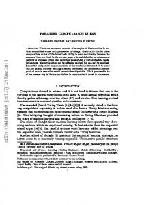
Schematic of the Ariane 5 launch vehicle and details of the JAV (front skirt of the two solid rocket boosters). [9] . . . . . . . . . . . . . . . . . Schematic of a cylindrical solid rocket engine and possible sources of oscillations represented by vorticity contours.[10] . . . . . . . . . . . . . . Matrices corresponding to LST, BiGlobal and TriGlobal Analysis. . . . Memory requirements for BiGlobal analysis of a compressible flow. . . . Linear Algebra libraries used in the project. . . . . . . . . . . . . . . . . Distribution of 8 processes across a 2 × 4 process grid. . . . . . . . . . LU factorization progression scheme. . . . . . . . . . . . . . . . . . . . . Decomposition scheme for the one-dimensional block column distribution and the one-dimensional cyclic column distribution. . . . . . . . . . . . Decomposition scheme for the one-dimensional block-cyclic column distribution and the two-dimensional block-cyclic distribution. . . . . . . . Data allocation to the processes inside a 2×2 process grid. . . . . . . . . Logical scheme of the solver. . . . . . . . . . . . . . . . . . . . . . . . . . Logical scheme of the interface. . . . . . . . . . . . . . . . . . . . . . . .
.
2
. . .
2 5 5
. 24 . 26 . 30 . 31 . . . .
Convergence analysis of the spectrum of the Blasius boundary layer corresponding to case 1 in table 4.1. . . . . . . . . . . . . . . . . . . . . . . . Comparison of the current calculation and Pinna’s results in [53] for case 1 in table 4.1. . . . . . . . . . . . . . . . . . . . . . . . . . . . . . . . . . . Streamwise velocity perturbation amplitudes corresponding to ω = 0.0424− i0.0019 and ω = 0.0394 − i0.0225. . . . . . . . . . . . . . . . . . . . . . . . Convergence of the BiGlobal spectrum for the Blasius boundary layer for case 1 in table 4.1. . . . . . . . . . . . . . . . . . . . . . . . . . . . . . . . Streamwise velocity perturbation amplitudes corresponding to ω = 0.0424− i0.0019 and ω = 0.0394 − i0.0225. . . . . . . . . . . . . . . . . . . . . . . . BiGlobal spectrum for the Blasius boundary layer for case 2 in 4.1 computed with a 15 × 90 grid. . . . . . . . . . . . . . . . . . . . . . . . . . . . Convergence of the BiG spectrum for the Poiseuille flow: A = 5, Re = 10400, α = 0.91. . . . . . . . . . . . . . . . . . . . . . . . . . . . . . . . .
v
32 32 33 40 43 44 45 46 47 48 49
vi
List of Figures 4.8 4.9 4.10 4.11 4.12 4.13 4.14 4.15 5.1 5.2 5.3 5.4 5.5 5.6 5.7 5.8 5.9 5.10 5.11 5.12 5.13 5.14
Real part of the eigenfunctions corresponding to the least stable eigenmode for Poiseuille flow in a rectangular duct with A = 5, Re = 10400 and α = 0.91. . . . . . . . . . . . . . . . . . . . . . . . . . . . . . . . . . Runtime in seconds for the LU-factorization with ScaLAPACK for testcase of size N = 8000. . . . . . . . . . . . . . . . . . . . . . . . . . . . . Runtime in seconds for the LU-factorization with ScaLAPACK for testcase of size N = 16000. . . . . . . . . . . . . . . . . . . . . . . . . . . . Efficiency of the LU-factorization with ScaLAPACK on the testcase with N = 8000. . . . . . . . . . . . . . . . . . . . . . . . . . . . . . . . . . . Efficiency of the LU-factorization with ScaLAPACK on the testcase with N = 16000. . . . . . . . . . . . . . . . . . . . . . . . . . . . . . . . . . . Efficiency for a single step of the Arnoldi factorization with N = 8000, nev = 10 and ncv = 20. . . . . . . . . . . . . . . . . . . . . . . . . . . . Efficiency for a single step of the Arnoldi factorization with N = 16000, nev = 10 and ncv = 20. . . . . . . . . . . . . . . . . . . . . . . . . . . . Mean runtime in seconds for a single step of the Arnoldi factorization with N = 16000, nev = 10 and ncv = 20. . . . . . . . . . . . . . . . . .
. 50 . 51 . 52 . 53 . 53 . 54 . 54 . 55
Complex Lamellar Bidirectional Vortex. . . . . . . . . . . . . . . . . . . . Mean tangential velocity obtained with the Complex Lamellar Bidirectional Vortex model with k = 0.1, Re = 1000. . . . . . . . . . . . . . . . . Velocity vectors in the r − z plane for the Complex Lamellar Bidirectional Vortex, k = 0.1, Re = 1000. . . . . . . . . . . . . . . . . . . . . . . . . . . Vortex Injection Hybrid Rocket Engine. Extracted from [48]. . . . . . . . Vortex Combustion Cold-Wall Chamber scheme. (Figure extracted by [24]) Spectra for varying number of discretization points with same boundary conditions as Batterson. . . . . . . . . . . . . . . . . . . . . . . . . . . . . Comparison between current calculation and Batterson’s results for radial velocity eigenmode corresponding to ω = 0.2178 + i 0.2940. . . . . . . . . Convergence of the spectrum for the Bidirectional Vortex with boundary conditions specified by (5.17)-(5.19). . . . . . . . . . . . . . . . . . . . . . Convergence analysis on the 10 modes nearest to the origin with varying number of points in both directions. . . . . . . . . . . . . . . . . . . . . . Error in the evaluation of eigenvalues 1 to 3 in figure 5.9 depending on the computational grid. . . . . . . . . . . . . . . . . . . . . . . . . . . . . Error in the evaluation of eigenvalues 4 to 7 in figure 5.9 depending on the computational grid. . . . . . . . . . . . . . . . . . . . . . . . . . . . . Amplitude in logarithmic scale of the eigenfunction corresponding to the most unstable mode: ω = 2.09 + i 0.65. . . . . . . . . . . . . . . . . . . . . Eigenfunction corresponding to the most unstable mode: ω = 2.09 + i 0.65. Amplitude in logarithmic scale of the eigenfunction corresponding to ω = 1.57 + i 0.03. . . . . . . . . . . . . . . . . . . . . . . . . . . . . . . . . . .
59 60 60 62 63 67 67 69 69 70 70 73 74 75
List of Figures
vii
5.15 Amplitude in logarithmic scale of the eigenfunction corresponding to ω = 0.05 − i 1.19. . . . . . . . . . . . . . . . . . . . . . . . . . . . . . . . . . . 76 5.16 Eigenfunction corresponding to ω = 0.05 − i 1.19. . . . . . . . . . . . . . . 77 6.1
Current results against results by Boyer[15] for Xin = 4, Xout = 8 and Re = 100. . . . . . . . . . . . . . . . . . . . . . . . . . . . . . . . . . . . 6.2 Convergence assessment with varying number of points Nx and Nr for Xin = 4, Xout = 8 and Re= 100. . . . . . . . . . . . . . . . . . . . . . . 6.3 Isocontours of the module of the axial and radial velocity in logarithmic scale for eigenmode corresponding to ω = 63.886 − i 28.127, for Re = 100, Xin = 4, Xout = 8. . . . . . . . . . . . . . . . . . . . . . . . . . . . . . . 6.4 Velocity perturbations in two different moments in time, obtained from eigenmode corresponding to ω = 63.886 − i 28.127, for Re = 100, Xin = 4, Xout = 8. Colors identify velocity magnitude. . . . . . . . . . . . . . . . 6.5 Comparison of results obtained with and without the use of the mapping technique proposed by Malik, for Re = 100, Xin = 4, Xout = 8. . . . . . 6.6 Error in the evaluation of the eigenvalues ω = 31.378 − i26.628 and ω = 56.565 − i27.826 with varying number of points along the axis, Re = 100, Xin = 4, Xout = 8, Nr = 100. . . . . . . . . . . . . . . . . . . . . . . . . 6.7 Spectra corresponding to Re = 2000, Xin = 4, Xout = 8, 300×100 nodes, with different parameters of the Malik mapping. . . . . . . . . . . . . . 6.8 Spectra corresponding to Re = 100, Xin = 4, Xout = 8, with and without the assumption of bidimensional perturbation with 300×100 nodes. . . . 6.9 Effect of grid resolution of a portion of the spectrum for Re = 100, Xin = 4, Xout = 8, with tridimensional perturbations. . . . . . . . . . . . . . . 6.10 Module, real and imaginary part of tangential velocity components for eigenmode corresponding to eigenvalue ω = 3 − i57, Re = 100, Xin = 4, Xout = 8, 325×100 nodes. . . . . . . . . . . . . . . . . . . . . . . . . . .
. 83 . 84 . 84 . 85 . 86 . 86 . 87 . 88 . 88 . 89
List of Symbols Acronyms CGL Chebychev-Gauss-Lobatto BiG BiGlobal DIAS DIspositif ASsouplisseur - Flexible Coupling System DNS Direct Numerical Simulation LES Large Eddy Simulation LST Linear Stability Theory (parallel flow assumption) LNP Local Non Parallel PVS Parietal Vortex Shedding RAM Random Access Memory VCCWC Vortex Combustion Cold Wall Chamber VESTA VKI Extensible Stability and Transition Analysis VIHRE Vortex Injection Hybrid Rocket Engine VKI Von Karman Institute Roman symbols a Speed of sound or chamber radius A Aspect Ratio c Phase velocity DN Differentiation matrix of the nth order L Characteristic length in the axial direction M Mach Number p Pressure perturbation P Pressure q Generic perturbation variable Q Generic flow variable r Radial coordinate Re Reynolds number t Time T Temperature u Streamwise or radial perturbation velocity component U Streamwise or radial velocity component viii
List of Figures v V w W x y z
Crosswise or azimuthal perturbation velocity component Crosswise or azimuthal velocity component Spanwise or axial perturbation velocity component Spanwise or axial velocity component Streamwise coordinate Crosswise coordinate Spanwise or axial coordinate
Greek symbols α Streamwise wave number β Spanwise wave number η Second computational coordinate θ Angular coordinate ω Temporal frequency Re(ω) and temporal growth rate Im(ω) ξ First computational coordinate ξi Chebyshev-Gauss-Lobatto point in ξ direction Subscripts and Superscripts Mean value of {·} {·} Dimensional equivalent of {·} {·}d ˜ Perturbation amplitude of {·} {·} {·}i Imaginary part of {·} {·}r Real part of {·}
ix
Chapter 1
Introduction Pressure oscillations are a major issue in long segmented solid rocket motors. Such oscillations were first identified during World War II and in the development of solid rocket boosters for the Space Shuttle and the Titan IV. These observations sparkled research interest both for military and space applications. Early research showed that grain separation lead to these low amplitude but sustained pressure and thrust oscillations of the order of 2 − 3% of the mean thrust and characterized by frequencies close to longitudinal acoustic modes of the engine. Therefore initially large interest was dedicated to methods based on energy balances to study acoustic frequencies even if with little success in the characterization of the phenomenon. In Europe extensive studies were later performed, particularly in the framework of the P230 programme, the primary booster for the European Ariane 5. While not of risk for the structure of the launcher, such perturbations could hinder attitude control and, above all, excite oscillations in the cryogenic main stage or possibly damage the payload. In order to avoid such issues, the DIAS - Dispositif ASsouplisseur (Flexible Coupling System) was designed: an elastomeric mechanical device that links the solid rocket boosters to the main stage [9]. Even though this system was designed so as to accomplish other tasks, being able to reduce these thrust oscillations would allow a serious reduction in the requirements for this device, thus reducing design costs in future projects and reducing the weight of this system therefore incrementing payload. Several efforts have been dedicated to understand the origin of these oscillations including direct numerical simulations, linear stability analysis studies and experiments, both with and without combustion (“cold-gas” experiments) on full scale and reduced scale motors. Three possible sources of oscillations were initially identified: • AVS - angle vortex shedding, shear instabilities generated in the shear layer between flow injected by angled faces of a single propellant grain; • OVS - obstacle vortex shedding, related to the presence of thermal protectors between fuel grains that represent obstacles for the flow and produce unsteady wakes;
1
2
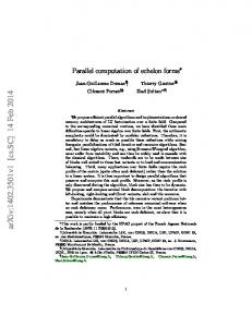
Main Stage Solid Rocket Boosters Figure 1.1: Schematic of the Ariane 5 launch vehicle and details of the JAV (front skirt of the two solid rocket boosters). [9] • PVS - parietal vortex shedding, hydrodynamic instability of the flow field not depending on some geometric irregularity. While OVS was initially believed to be the source of the main pressure oscillations, their role is yet to be fully understood. Experiments with combustion with metallic inhibitors do not show large oscillations while they have been observed in systems lacking of such thermal protections. Therefore OVS is now considered a secondary mechanism that can contribute to the presence of pressure perturbations. PVS, on the other hand, has been successfully linked to such large oscillations thanks to direct numerical simulations by Vuillot [64], experiments in cold-gas setups like those performed by Varapaev and Yagodkin [63, 66], Brown and Dunlap [18, 31], Avalon [8] and multiple theoretical studies.
Figure 1.2: Schematic of a cylindrical solid rocket engine and possible sources of oscillations represented by vorticity contours.[10] One of the main features of this phenomenon is that the frequencies of these pressure oscillations, while being close to the acoustic ones, drift over the course of firing tests, following frequencies identified through hydrodynamic stability theory. This drift is
Different approaches to stability
3
explained by the slight change in injection velocity or in radius of the chamber caused by grain regression. These variations modify dimensional “hydrodynamic” frequencies while leaving unchanged the acoustic ones. The most accepted explanation for this mechanism is that hydrodynamic modes are first excited by outside perturbations and produce PVS at position near grain breaks. If these frequencies are close to acoustic ones, once they reach the outlet, acoustic waves are reflected back through the chamber. These waves interact again with injection breaks thus exciting again the same hydrodynamic modes. This mechanism is sometimes described as acoustic coupling. While much research has already been dedicated to this subject there are some aspects that have still to be fully analysed like compressibility and combustion effects or the possibility of employing particle injection to reduce oscillations. Similar issues could appear in other space propulsion systems. It is therefore important to promptly analyse stability properties in novel applications, in order to identify optimal configurations or parameters to control such instabilities. Two novel systems to which such analysis should be applied are the Vortex Injection Hybrid Rocket Engine (VIHRE) and the Vortex Combustion Cold-Wall Chamber (VCCWC). These systems are the product of the idea of a flow configuration described as a bidirectional vortex. This configuration was introduced to enhance regression rate in hybrid rocket engines or to double as a cooling system for liquid rocket engines. This technology was first introduced at ORBITEC by Knuth et al. [25] and Chiaverini et al. [24], initially developed under a NASA Small Business Innovation Research project and is currently under further development. Some preliminary stability studies have been performed but still a lot of research can be dedicated to the subject given the large variety of possible configurations that can be employed.
1.1
Different approaches to stability
In order to analyse stability properties of a certain flow field, multiple techniques can be employed. The first technique that can be used is Direct Numerical Simulation (DNS). In this case the flow field is directly simulated by means of the Navier-Stokes equations. The evolution of perturbations is completely described from the initial growth up to interaction between disturbances and eventually flow breakdown. Very fine grids are required to capture this evolution, therefore, making this method the most computationally expensive. While this method allows a complete characterization of the flow field the computational cost associated with it makes it prohibitive to analyse the effects of several parameters on the stability properties. A less expensive approach is represented by Large Eddy Simulations (LES). It aims to resolve larger turbulent scales while modelling smaller ones by means of Sub-Grid Scale (SGS) models. These models will influence final results, therefore they often require a fine tuning for the specific application. This approach allows a big reduction in compu-
Memory requirements
4
tational costs for free flows, however, for regions located near walls, grid requirements are often really close to those of DNS and this is exactly the case for flows inside engines. The last numerical method in order of complexity is the use of linearised stability equations. In this case perturbations are obtained by the Navier-Stokes equations linearised around a mean flow for small state perturbations. Different formulations can be obtained depending on the assumptions applied to the mean flow. The simplest case corresponds to LST analysis and to the assumption of a parallel flow, that is the mean flow depends on only one spatial variable. In this case, stability equations form a system of linear ODEs that, once discretized, become an algebraic eigenvalue problem. If the mean flow is assumed to be mildly varying in one direction then Parabolised Stability Equations (PSE) are obtained. When the base flow depends on two or three spatial variables the obtained approaches are called BiGlobal and TriGlobal Stability analysis. The BiGlobal approach will be applied throughout this work as it allows the correct description of the axisymmetric flows considered, both for the accelerating flow field in solid rocket engines and the complex three-dimensional flow describing the bidirectional vortex. Earlier works in literature have applied both LST and a slightly modified treatment known as Local Non Parallel (LNP) to both configurations therefore introducing a stronger approximation than the one employed here. The linearisation of the Navier-Stokes equations means that this method will not be able to capture either non-linear interactions between modes nor flow breakdown. This technique, however, has already been successfully applied to incompressible stability analysis of solid rocket engines and provides a big reduction in computational costs compared with LES and DNS.
1.2
Memory requirements
While it is true that a large reduction of memory and time requirements is obtained with respect to LES and DNS, BiGlobal stability analysis presents computational costs rather large compared with LST. As the base flow depends on two spatial variables, stability equations form a system of partial differential equations in two spatial coordinates, therefore a discretization needs to be performed in both directions, thus resulting in an eigenvalue problem much larger than the one corresponding to LST. In figure 1.3 matrices corresponding to LST, BiGlobal and TriGlobal analysis are compared by assuming that the same number of points should be used in every direction to obtain a good resolution. As a reference, figure 1.4 shows how much memory is required if the two matrices that define the BiGlobal compressible eigenvalue problem are to be fully memorised. It should be clear that in order to analyse complex flow fields, that require fine grids in order to completely capture stability properties, algorithms that make use of distributed memory and parallel computations should be employed.
5
Aim and Structure of the Thesis
LST BiG
TriG
Memory (GB)
Figure 1.3: Matrices corresponding to LST, BiGlobal and TriGlobal Analysis.
256 24
75 × 75 136 × 136 number of points
Figure 1.4: Memory requirements for BiGlobal analysis of a compressible flow.
1.3
Aim and Structure of the Thesis
The main objective of the following work will be to analyse stability properties of the two configurations presented by means of the BiGlobal stability approach. First, this tool will be applied to the Complex Lamellar Bidirectional Vortex, one of the analytical solutions that model the flow field inside VIHRE and VCCWC. The BiGlobal tool will also be applied to the incompressible flow inside cylindrical solid rocket engines. A similar analysis has been addressed already by Boyer et al. [15]. In the present work the Malik mapping technique will be used in place of a multidomain one. This analysis will be the basis of future forks analysing compressibility effects. In order to achieve these results a preliminary objective had to be achieved: the implementation of a parallel solver for large scale eigenvalue problems. This work will be included as part of the VESTA Toolkit project developed at the von Karman Institute for Fluid Dynamics, thus adding to the set of tools available for stability and transition prediction. This work will be organised in the following way. In chapter 2 a quick review of the basic concepts of stability analysis and the discretization method will be presented, followed by an introduction on the Implicitly Restarted Arnoldi algorithm employed in the solution of large scale eigenvalue prob-
Aim and Structure of the Thesis
6
lems. Chapter 3 will focus on the implementation of the parallel solver. First the main libraries employed in the development will be described, followed by the description of the implementation of the algorithm and its collocation inside the VESTA toolkit alongside a discussion on how this compares with similar works in literature. Chapter 4 will regard the validation of the solver on LST and BiGlobal problems followed by the evaluation of the performances of the algorithm. Chapter 5 will focus on the BiGlobal stability analysis of the Complex Lamellar Bidirectional vortex. In chapter 6 a similar analysis will be performed on the incompressible Taylor-Culick flow, modelling the flow field inside solid rocket engines.
Chapter 2
Theoretical and Numerical Background on Stability The main purpose of Hydrodynamic Stability analysis is to analyse the response of a flow, under certain conditions, to small or moderate perturbations. When the response of the fluid system is limited and the flow returns to the initial configuration the flow field is deemed as stable. On the other hand, if there are certain perturbations that grow and modify definitively the flow field, it is deemed unstable. There are multiple ways to study stability properties and many mechanisms can be the cause of instability. The easiest way to tackle this problem is to start by assuming that the perturbations are very small in amplitude with respect to the mean flow and thus Linear Stability Theory can be applied. In section 2.1 a quick review about Linear Stability Theory and its many formulations is presented. Section 2.2 will then describe the discretization method that will be employed throughout this work. In section 2.3 the VESTA Toolkit, in which the developed tools will be included, is briefly described. Following sections 2.4, 2.5 and 2.6 will present the theoretical background on the Implicitly Restarted Arnoldi Method used to solve large scale eigenvalue problems. At last section 2.7 will describe the spectral transformations.
2.1
Linear Stability Theory
The solution of the Navier-Stokes equations can be expressed as the superposition of a mean flow and a perturbation term. The mean flow is, in most applications, a steady solution of the Navier-Stokes equation and describes the flow field of which the stability properties are to be analysed. The solution can therefore be written as: Q(x, t) = Q(x) + q(x, t)
(2.1)
where Q identifies the state of the fluid system at any time, Q identifies the mean flow and q is the perturbation term. Equation (2.1) can be substituted in the Navier-Stokes 8
9
Linear Stability Theory
equations in order to obtain the evolution of the complete flow field once a perturbation of some kind has been applied. By substituting the condition that the mean flow is already a steady solution of the N-S equations, one is able to obtain a system of nonlinear partial differential equations. These are often named as the Perturbation Equations as they describe the evolution of the perturbation term. In Linear Stability Theory the fundamental assumption is then that perturbations are small enough that any non-linear term in the perturbation equations can be neglected with respect to linear terms. This assumption will mean that the following analysis will not be able to capture non-linear mechanisms like interaction between perturbations or vortex breakdown. At this point a linear homogeneous system of partial differential equations and boundary conditions has been obtained: L{q} = 0 .
(2.2)
In this case any possible solution can be obtained as linear combination of the particular solutions of this system of equations. The differential operator L and correspondingly the coefficients that appear in (2.2) might depend on space but not on time as the mean flow is steady. Every possible perturbation can therefore be obtained by combination of solutions that take the following shape: q(x, t) = q˜(x)e−iωt .
(2.3)
Such a condition can be obtained both by the method of separation of variables or by applying the Laplace transform to (2.2). The following analysis is often named as modal analysis and every term of type (2.3) is referred to as a mode and perturbations are superpositions of non interacting modes. Every perturbation must be clearly a real quantity while these modes are expressed as complex functions. However, if one function of kind (2.3) is solution of the perturbation equations, its complex conjugate will also be solution and the perturbation at any moment can be expressed as sum of these two solutions so that : n
q(x, t) = q˜(x)e−iωt + c.c. = 2Re (˜ q (x)e−iωt
o
.
(2.4)
Alternatively one can observe that both the real and imaginary part of (2.3) will be separately solutions of (2.2) as the system is linear, and we will be interested only in the real part of the solution.[30] Substituting (2.3) in (2.2) results in the perturbation amplitude equations or stability equations. Different formulations can be obtained depending on the considered mean flow. The simplest case is obtained when the parallel flow assumption can be applied, that is the mean flow can be considered as depending on only one spatial variable. Then, the following condition can be applied: Q ≡ Q(z)
→
q = q˜(z)ei(αx+βy−ωt) .
(2.5)
10
Linear Stability Theory
In many cases however this assumption is not applicable and the mean flow must be considered dependent on two or three spatial coordinates. In this case: Q ≡ Q(y, z)
Q ≡ Q(x, y, z)
→
→
q = q˜(y, z)ei(αx−ωt) ,
(2.6)
q = q˜(x, y, z)e
(2.7)
−iωt
.
From now on, the first approach, corresponding to (2.5), will be referred to as LST, approaches corresponding to (2.6) and (2.7) will be referred to as BiGlobal Stability Analysis and TriGlobal Stability Analysis respectively [61]. In the following work, when the mean flow is considered dependent on one spatial variable, that direction will be described differentially and it will be deemed as an eigenfunction direction as the amplitude q˜ will directly depend on it. When the mean flow is independent on one spatial direction, that direction will be said to be treated spectrally and will be described as an homogeneous or spectral direction. This is justified as q˜ will also be homogeneous and q will behave like a modal wave in that direction. Treating one direction as spectrally or differentially is analogous to performing a local or global stability analysis. For example, if for a flow field the x and z directions are treated spectrally, one is neglecting the dependency of the mean flow on these variables and therefore this analysis will only be valid locally for one specific position (x, z). However, if the dependency of Q on x is retained the global stability properties of the flow evolving in the x − y plane can be captured. The corresponding eigenfunctions in this case might behave in different ways than modal waves in the x direction.1 For LST and BiG analysis two different approaches can be followed. The first approach is referred to as temporal stability, in this case α (and β for LST) are considered real quantities and, fixing their value, the linearized stability equations become a generalized eigenvalue problem. In this case the eigenvalues ω = ωr +i ωi identify the temporal frequency (ωr ) and growth rate (ωi ) corresponding to the eigenfunctions/amplitude q˜. This analysis needs to be repeated for every possible value of α (and β). If, for any wavelength, there is at least one eigenvalue ω with imaginary part more than zero the corresponding mode will grow in time and the mean flow is deemed as unstable. This is the only possible approach for TriGlobal Stability Analysis. The second possible approach is to consider ω a real number and to solve the eigenvalue problem for complex values of α. In this case, for every frequency ω, the spatial frequency αr and spatial growth rate −αi are obtained for every corresponding eigenmode q˜. This approach is referred to as spatial theory and is often used in order to describe perturbations that grow in space rather than in one specific location. It is also at the basis of the eN -method used to predict the position of transition for many practical applications. This work will focus only on temporal stability. 1 This is different from the concept of global stability introduced in the analysis of absolute/convective instability of parallel or weakly non-parallel flows, a discussion on this term is presented by Theofilis in [61].
11
Chebyshev Collocation Method
2.2
Chebyshev Collocation Method
In order to solve the eigenvalue problem specified by the stability equations, for most practical application, the only possible approach is to use a numerical method. To this end the differential operators that appear in the stability equations need to be discretized. In the following work the Chebyshev Collocation Method is used. Details of the derivation and implementation can be found in [62], here only the highlights of this method will be presented. The first step is to define a set of Chebyshev-Gauss-Lobatto points: ξj = cos
�
jπ N
�
for j = 0, 1, ..., N.
(2.8)
Given a generic function u defined on the interval [−1, 1], it is possible to approximate its derivative by first defining a polynomial p respecting the interpolation condition 0 p(ξj ) = uj for j = 0, 1, ..., N and then computing its derivative du dξ (ξj ) ≈ wj = p (ξj ). Lagrange interpolation is used to obtain p as function of the values uj so that: u≈
N X
uj λj (ξ)
where
λj (ξ) =
k=0
N Y ξ − ξk
ξ k=0 j j6=k
− ξk
(2.9)
.
By employing this approximation wj can be expressed as linear combination of the N + 1 values uj and by extension w ≡ {wj } as function of u ≡ {uj } : w = DN u .
(2.10)
The Chebyshev differentiation matrix DN can be described by its coefficients:
DN,ij =
with
2N 2 + 1 6 2+1 2N − 6
i=j=0 i=j=N
ξi − 2(1 − ξi )2 ci (−1)i+j
i = j = 1, ..., N − 1 i 6= j
cj (ξi − ξj ) ci =
(
2 1
(2.11)
i, j = 1, ..., N − 1
i = 0 or N otherwise .
By discretizing the stability equations with this method, one obtains an algebraic eigenvalue problem where the eigenvectors contain an approximation of the values of the eigenfunctions of the original problem on the collocation points.
12
The VESTA Toolkit
In most cases the physical domain doesn’t coincide with the computational one [−1, 1], therefore a transformation ξ = ξ(x) is used to map every point on the physical grid {xj } to the CGL grid {ξj }. Derivatives in the physical domain can be obtained as: du(ξ) dξ du(ξ) = . (2.12) dx dx dξ With the discretization defined before one obtains that: w = Txξ DN u where Txξ is a diagonal matrix of elements mapping technique has been applied: x=
dξ dx (xj ).
(2.13) In the following work only the Malik
xi xmax (1 + ξ) xmax − ξ(xmax − 2xi )
(2.14)
It maps ξ ∈ [−1, 1] into x ∈ [0, xmax ] with half of the points in [0, xi ]. The previous treatment is valid when solving a differential problem where the solution depends on only one variable. In the case of the BiGlobal stability analysis the stability equations are a system of partial differential equations and the solution needs be found on a bidimensional grid. This physical grid will need to be mapped to a bidimensional computational domain (ξ, η) ∈ [−1, 1] × [−1, 1] with in general Nξ and Nη points. The common approach is then to locate the values of the function on every point of the grid in a vector by numbering each ot these values in a column-wise order. In this case it can be shown that the Chebyshev derivative matrices can be obtained as: Dx = (Txξ DNξ ) ⊗ INη
and
Dy = INξ ⊗ (Tyη DNη )
(2.15)
where ⊗ is the Kronecker product. Higher order derivative matrices can be obtained by properly multiplying the previous ones, for example Dxx = (Dx )2 .
2.3
The VESTA Toolkit
The work developed throughout this thesis in the implementation of a parallel solver was introduced as part of the efforts in the continuous development of the VESTA Toolkit. VESTA stands for VKI Extensible Stability and Transition Analysis toolkit. It has been developed at the Von Karman Institute for fluid dynamics by Pinna in [53] as an extensible toolbox comprising a variety of standard tools that can be employed to analyse stability properties in many different applications. The fundamental idea behind this project is the extensibility, keeping this aspect as a basilar value in every part of the development allowed the introduction of many techniques by the hand of different collaborators that have worked over the course of years on the project. At this stage, the code is mainly divided in two parts dealing with different aspects of the solution of the stability equations. One part of the code, dealing with the automatic derivation of stability equations, is made up of a series of scripts using MAXIMA,
Introduction to the Arnoldi Factorization
13
licensed as GNU-GPL. This tool can be used to obtain an error free formulation of stability equations under different assumptions allowing the use of user-defined curvilinear coordinate systems, various assumptions for the dependency of transport coefficients and stability analysis approaches. The automatic implementation tool provides MATLAB scripts that compute the eigenvalue problem for stability analysis without the intervention of the user, avoiding therefore natural man-made errors in the transcription of the hundreds of terms that appear in the equations. At the time of this work an automatic implementation tool is under development for PSE analysis while it is in operational regime both for LST and BiGlobal analysis. The second part of the code is written in MATLAB® (running as well under OCTAVE, licensed under GNU-GPL) and provides multiple tools for the discretization and solution of linear stability problems including multiple boundary conditions and techniques like the eN -method. At the time of this work a BiGlobal Tool developed by Groot and Pinna [39] was already available. Minor interventions were however introduced in the code, including new boundary conditions and minor modifications in order to better exploit the sparse nature of the matrices involved in the computations, producing better performances and lower memory requirements.
2.4
Introduction to the Arnoldi Factorization
Before describing the Arnoldi algorithm some other fundamental ideas need to be introduced. The following is in no way a complete treatment of the subject but hopefully it will provide the background necessary to understand the implementation of the solver and the various parameters that control performances of the algorithm. For more details on the derivation of the Arnoldi algorithm refer to [57, 58]. Invariant Subspaces and Shur Decomposition A subspace S of Cn×n is called an invariant subspace of A if AS ⊂ S. If A ∈ Cn×n , X ∈ Cn×k and B ∈ Ck×k satisfy: AX = XB (2.16) then S =Range(X) = {v : there exists at least one y ∈ Cn such that Xy = v}. If the columns of X are linearly independent then they are also a basis for S and σ(B) ⊂ σ(A). With σ(A) standing for the spectrum, that is the set of all eigenvalues, of A. Theorem 2.1 Let A ∈ Cn×n , then there is a unitary matrix Q and an upper triangular matrix R such that AQ = QR (2.17) The diagonal elements of R are the eigenvalues of A and the columns of Q are called Shur vectors. This theorem is at the foundation of the QR-algorithm. This algorithm begins with an unitary similarity transformation V of A to reduce it to Hessenberg form that is a
Introduction to the Arnoldi Factorization
14
matrix with all the elements below the first subdiagonal equal to zero. This matrix is then reduced to triangular form. Krylov Subspaces and projection methods The QR-Algorithm cannot be applied for large-scale problems because of its memory and time requirements. If only a limited portion of the spectrum is sought then other methods, as those based on the Krylov Subspaces, are a more suitable choice. The Krylov subspace is defined as: Kk (A, v1 ) = Span{v1 , Av1 , A2 v1 , . . . , Ak−1 v1 } Given a Krylov subspace of A, a vector x ∈ Kk (A, v1 ) is called a Ritz vector with corresponding Ritz value θ if the following Galerkin condition is satisfied. < w, Ax − xθ >= 0,
for all w ∈ Kk (A, v1 )
(2.18)
It is clear that the Ritz pair (x, θ) can be viewed as an approximation of eigenvalues and eigenvectors of A. Let W be a matrix whose columns form an orthonormal basis of Kk (A, v1 ) and B = W H AW , pˆ(λ) = det(λI − B) that is pˆ is the characteristic polynomial of B, then the following lemmas can be demonstrated. Lemma 1 For the quantities defined above: 1. (x, θ) is a Ritz-pair if and only if x = W y with By = θy, that is θ is an eigenvalue of B and y is its corresponding eigenvector. 2. If y is any vector in Ck then AW y − W By = γ pˆ(A)y for some scalar γ . 3. If (x, θ) is any Ritz-pair for A with respect to Kk (A, v1 ) then: Ax − xθ = γ pˆ(A)v1 It is possible to show that Kk (A, v1 ) is an invariant subspace of A if and only if v1 = V y where V is such that AV = V R with V H V = Ik and R is k×k upper triangular. It is also possible to find a convenient orthonormal basis V such that B = V H AV = H upper Hessenberg with non-negative subdiagonal elements and in this basis: AV = V H + feTk
where f = γ pˆ(A)v1 and V H f = 0
(2.19)
If a v1 can be found, that is linear combination of k eigenvectors of A then Kk si an invariant subspace of A and f = 0. By Lemma 1 we obtain that in this case Ax−θx = 0, which means that the Ritz values σ(H) ⊂ σ(A) and the corresponding Ritz vectors are the eigenvectors of A.
Implicitly Restarted Arnoldi Method
2.5
15
Implicitly Restarted Arnoldi Method
The Arnoldi Method is the algorithm by which the factorization (2.19) is computed. Once such a factorization is obtained the eigenvalues of H are Ritz pairs of A and represent only an approximation of the eigenvalues of A. The information that can be extracted at this point is nonetheless essential as it can be exploited to define a new starting vector v1 and restart the algorithm. The Algorithm 1 describes the procedure defined by the Arnoldi Method to obtain the columns of V and the elements hi,j of H. This procedure is halted once the maximum number of vectors defined by the user has been obtained or if one vk is equal to zero. If the latter occurs v1 is already a linear combination of k − 1 eigenvectors and the corresponding eigenvalues are exactly the eigenvalues of H. This process can also be interpreted as a partial orthogonal reduction of A in Hessemberg form. At the end of k steps the first k vectors vj will form the Vn×k matrix, the elements hi,j , besides the last one hk+1,k , form Hk×k and f = hk+1,k vk+1 . Special care must be taken to be sure that the generated basis is orthogonal because of computing errors. The direct application of the Arnoldi Algorithm might require a large number of iterations to obtain the eigenvalues and eigenvectors with the accuracy desired. This would imply both longer times in the diagonalization of the Hessenberg matrix and heavier memory requirements. Orthogonalization error become more relevant as the number of steps increases and the same can be said for the computational costs related to the reorthogonalization step necessary to control them.[57] Algorithm 1 The k-step Arnoldi Factorization - Start with an arbitrary vector v1 with norm 1 - Repeat for j = 2, 3 . . . , k + 1 - vj = Avj−1 - for i from 1 to j − 1
- hi,j−1 = vi · vj - vj = vj − hi,j−1 vi
- hj,j−1 = kvj k - vj =
vj hj,j−1
Explicit Restarting One way to avoid these problems is restarting the Arnoldi Algorithm. The information that can be retrieved from a partial application of the algorithm can be exploited to define a new starting vector. This approach brings to the Explicitly Restarted Arnoldi Algorithm. After applying k steps of the Arnoldi Factorization, a new starting vector is defined
16
Implicitly Restarted Arnoldi Method
by multiplying the previous starting vector by a polynomial of A. The polynomial is designed to enhance the components of the new vector in the directions of the wanted eigenvectors and damp its components in the unwanted directions. In this way the new Krylov subspace should become invariant to A with a lower number of vectors. If this is the case a better approximation, involved in considering the Ritz values as the eigenvalues of A, is obtained. Another similar technique would be defining the new starting vector as a linear combination of the computed Ritz vectors of interest. For a deeper insight in the way the polynomial is defined or the way the wanted Ritz vectors are selected and weighted refer to [41, 42]. Implicit Restarting Another approach to restarting that offers a more efficient and numerically stable formulation is called implicit restarting. Implicitly restarting allows the extraction of interesting informations from large Krylov subspaces in a similar way to the explicit restarting but without computing the whole Krylov subspace at each restart. This is accomplished by first computing the Arnoldi factorization of length m = k + p: AVm = Vm Hm + fm eTm
(2.20)
In order to compress the information of interest in a k-step factorization p QR-steps are applied. This is done by computing p matrices Qj where Qj is the orthogonal matrix obtained from the QR factorization of Hm − µj I for p different shifts µj defined in a proper way (see later). By defining Q = Q1 Q2 . . . Qp , applying the p-shifts one obtains: + AVm+ = Vm+ Hm + fm eTm Q
(2.21)
+ = QT H Q and V + = V Q. It may be shown that the first k − 1 terms of where Hm m m m eTm Q are equal to zero, then by equating the first k columns one obtains a new k-step factorization: AVk+ = Vk+ Hk+ + fk+ eTk (2.22)
From this point other p steps of the factorization can be applied to return to the original m-step form. Each of these shifts applied results in the application of a polynomial of A of degree p to the starting vector: v1 ← Ψ(A)v1
with
Ψ(λ) =
p Y 1
(λ − µj )
(2.23)
One could observe at this point that the difference between the implicit and explicit restarting technique is that by applying the implicit technique the first k step of the factorization need not to be computed again after the restart and only p steps of the factorization need to be applied at each subsequent iteration. If m = n then f = 0 and this technique is exactly the same as the Implicitly Shifted QR iteration. If m < n the first k columns of V and H(1:k,1:k) are mathematically
17
Implicitly Restarted Arnoldi Method
equivalent to the matrices found in the Implicitly Shifted QR iteration and as such the implicitly restarted Arnoldi method can be seen as a truncated version of that method. An important factor in the efficiency of the restarting technique is the way the shifts are computed. The choice needs to be guided in order to filter unwanted information from the starting vector. A shift selection strategy that has been proved to be the most efficient one is called the Exact Shift Strategy. In this method one computes σ(H) and sorts this into two disjoint sets Ωω and Ωu . The k ritz values in Ωω are regarded as the wanted eigenvalues of A while the p values in Ωu are used as shifts µj . By applying this strategy σ(Hk ) = Ωω and v1 is a linear combination of the “wanted” ritz vectors. Algorithm 2 Implicitly Restarted Arnoldi Algorithm - Start with the m-step Arnoldi Factorization: AVm = Vm Hm + fm eTm - For l = 1, 2, 3 . . . until convergence: - compute σ(Hm ) and select a set of p shifts µ1 , µ2 . . . µp based upon σ(Hm ) or some other information - qT = eTm - For j = 1, 2, . . . p - Factor [Qj , Rj ] = qr (Hm − µj I); - Hm = QH j Hm Qj ; Vm = Vm Qj ;
- q = qH Qj ;
- fk = vk + 1; Vk = Vm(1:n,1:k) ; Hk = Hm(1:k,1:k) ; - starting from the new k-step Arnoldi factorization AVk = Vk Hk + fk eTk apply p additional steps for the Arnoldi process to obtain a new mstep Arnoldi factorization.
The objective of the implicit restart is to enhance the components of the starting vector v1 in the directions of the wanted eigenvectors. If v1 has an expansion as a linear combination of eigenvectors {xj } of A the effect of polynomial restarting is the following: v1 =
n X
j=1
xj γj → ψ(A)v1 =
n X
j=1
xj ψ(λj )γj
(2.24)
18
Accuracy of the Arnoldi Algorithm
If at every restarting step the same shifts were applied, then, after l iterations, the j-th original expansion coefficient would be attenuated by a factor �
ψ(λj ) ψ(λ1 )
�l
where ψ(λ1 ) is the largest value ψ(λj ). Thus the first k components become dominant in this expansion and the remaining ones decay and become less significant.
2.6
Accuracy of the Arnoldi Algorithm
The accuracy of the Arnoldi Algorithm is closely linked to the stopping criterion used to define when the algorithm has computed an eigenvalue of acceptable accuracy. Once the Arnoldi factorization is obtained, if one says Hm s = sθ with ksk = 1 and x ˆ ≡ Vm s, then: kAˆ x−x ˆθk = kfm k|eTm s| . (2.25)
Equation (2.25) means that (ˆ x, θ) is a good approximation of an eigenpair of A if the last component of the corresponding eigenvector of Hm , (|eTm s|), is small. Usually this is the way convergence takes place. It is also possible to obtain convergence by reducing kfm k, in this case all m eigenvalues of Hm are likely to be good approximation of m eigenvalues of A. It can be shown that the following equation also holds: (A + E)ˆ x=x ˆθ
with E ≡ −(eTm s)fm x ˆH .
(2.26)
The pair (ˆ x, θ) is therefore an exact solution of a perturbed problem, with the entity of the perturbation linked to the two quantities described before. In the non-Hermitian case a small kEk doe not necessarily imply a small error in the approximation of the eigenpair with the Ritz pair. Theorem 2.2 Suppose that λ is a simple eigenvalue of A nearest the eigenvalue of A + E, if y and x are the left and right eigenvectors of unit length then: |λ − θ| ≤
� � kEk 2 + O kEk |yH x|
(2.27)
For Hermitian matrices y = x, then it is immediate to evaluate from the previous theorem an upper bound for the error. If the left and right eigenvectors are nearly orthogonal, then even if kEk ≈ εM kAk, where εM is machine precision, θ may contain only a few digits, if any, of accuracy. A good estimate is that if |yH x| ≈ 10−d and εM ≈ 10−t then the leading t − d decimal digits of θ will be the same as those of λ. As for the estimates of the eigenvectors, this evaluation is complicated by the fact that scaling the starting vector by a complex non zero quantity one always obtains a new eigenvector. In this case an evaluation of the accuracy can be done by computing an estimate of φ: the angle between the exact eigenvector and its Ritz estimate.
19
Spectral Transformation "
#
λ rH 12 Theorem 2.3 Suppose that AQ = Q with λ a simple eigenvalue of A closest 0 R22 to θ eigenvalue of A + E with corresponding eigenvectors x and x ˆ. If φ is the positive angle between x and x ˆ then φ≤ where sep(λ, R22 ) ≡ minz6=0
� � 2kEkF + O kEk2F sep(λ, R22 )
kλzH −zH R22 kF kzkF
(2.28)
and kEkF = (trace(E H E)) 2 . 1
The sep variable includes in the estimate of the error on the eigenvector a dependency on clustering of eigenvalues and non normality as it can be proven that: sep(λ, R22 ) ≤ sep(λ, R22 ) ≤ kr12 k q
min
λi 6=λ,λi ∈σ(R22 )
|yH x|
1 − |yH x|2
|λ − λi | for non zero r12
(2.29) (2.30)
The conclusion that must be drawn is that the eigenvalues of a non-symmetric matrix may be very sensitive to perturbations such as those introduced by round off errors. Moreover these results show that, while for normal matrices a good evaluation of the accuracy can be computed, for non-normal matrices with a high level of non-normality the best that can be said is that one has computed the exact eigenvalues of a nearby matrix. In the implementation of the implicitly restarted Arnoldi algorithm that is used in this work, the ARPACK library, the Ritz pair is considered converged when kfm k|eTm s| ≤ max(εM kHm k, tol · |θ|)
(2.31)
This implies that since |θ| ≤ kHm k ≤ kAk, equation (2.26) is satisfied with kEk ≤tolkAk.
2.7
Spectral Transformation
In order to accelerate convergence for most of the iterative methods that solve for a limited part of the spectrum, a spectral transformation is often applied. This is true as well for the Arnoldi method. When a restarting algorithm is not applied the Arnoldi Method would converge first to the eigenvalues of largest moduli. Even in the case of the Implicitly Restarted Arnoldi Method the acceleration provided by the restarting algorithm is enhanced when the interesting part of the spectrum is far from the one in which one is not interested. If A ∈ C n×n with eigenvalue λ and eigenvector x: - If p(τ ) = γ0 + γ1 τ + γ2 τ + . . . γk τ k then p(λ) is an eigenvalue of p(A) = γ0 I + γ1 A + γ2 A2 + . . . γk Ak with x that is the corresponding eigenvector.
20
Spectral Transformation
) −1 - If r(τ ) = p(τ q(τ ) where q(A) is non singular, if r(A) = [q(A)] p(A) then r(λ) is an eigenvalue of r(A) with corresponding eigenvector x.
Transformations based on these results are called spectral transformations because instead of solving for the starting eigenvalue problem one solves for a new transformed problem that has the same eigenvector but transformed eigenvalues. By choosing in the appropriate way the transformation, the convergence rate could be vastly accelerated and the part of the spectrum of interest can be more easily identified. This is done by mapping the eigenvalues of interest to have largest moduli and to be vastly separated from the undesired ones. Moreover, spectral transformations are necessary if the B matrix of the generalized eigenvalue problem is singular or ill-conditioned. The transformation that is used most often with the Arnoldi method is the shift-invert transformation, while specifically for eigenvalue problems related to stability analysis the generalized Cayley transformation is a common choice. [50, 45] Shift-Invert Transformation The shift-invert transformation is the simplest rational transformation where instead of solving for the starting eigenvalue problem one solves for the problem: (A − σB)−1 Bx = νx (2.32) The parameter σ used in the transformation is called shift-invert preconditioner or simply shift-invert. The relationship between the eigenvalues of the original eigenvalue problem and those of the transformed problem is: ν=
1 , λ−σ
λ=σ+
1 . ν
(2.33)
In this case the starting eigenvalues closer to the shift-invert are mapped to eigenvalues with largest moduli while those farther from the preconditioner are mapped to ones with small moduli. When λi 6= σ the circle with center σ and radius |λi − σ| in the λ-plane is mapped to a circle in the ν-plane with center 0 and radius |νi | = |λi1−σ| . When the Arnoldi Algorithm is applied to search for the first k eigenvalues of largest module one can be sure that, if the algorithm has converged, all the eigenvalues outside the circle of center 0 and radius equal to the module of the k th eigenvalue have been found. Then, as the algorithm is applied to the transformed problem, the domain of confidence in the λ-plane is the circle centered in σ and radius |ν1k | . Generalized Cayley Transformation While the shift-invert transformation is simple and useful in most practical applications it can make the eigenvalue problem illconditioned. This problem is even more relevant when an iterative solver is applied to solve the linear system of equations. This is often solved in linear stability analysis by applying the Generalized Cayley transformation. The Generalized Cayley transform is defined by: (A − α2 B)x = µ(A − α1 B)x
(2.34)
21
Spectral Transformation The relationship between the original eigenvalues and the transformed ones is: µ=
λ − α2 , λ − α1
λ=
µα1 − α2 . µ−1
(2.35)
With this transformation the circle centered in 0 and with radius c in the µ-plane is mapped to a circle with center and radius defined by: c2 α1 − α2 , O= c2 − 1
c r= 2 (α1 − α2 ) . c −1
(2.36)
Once the domain of confidence has been defined from |µk | in the µ-plane, the corresponding domain of confidence in the λ-plane is inside a circle that can be computed by substituting |µk | in place of c in (2.36). 2 If α1 and α2 are chosen so that they have same real part and Im(λ) < Im( α1 +α )< 2 Im(α2 ) for every λ, then |µ| will be always larger then 1 and eigenvalues close to α1 will be mapped to the ones with largest moduli. In this way undesired eigenvalues are mapped to the ones close to the unit circle being separated from the ones of interest. For this reason, the Cayley transform usually yields a better conditioned linear system of equations than the shift-invert transform.
Chapter 3
Architecture and Implementation Parallel Computing is a type of computation in which many operations are executed at the same time. It is based on the principle that often large computations linked to lengthy operations or large amount of data can be divided into smaller ones. Many serial and parallel libraries have been developed for scientific applications, many of them are now part of the standard. This chapter will be dedicated to the description of the implementation of a parallel solver for the solution of an eigenvalue problem. The Implicitly Restarted Arnoldi Algorithm is applied through the use of several Fortran/C libraries. Figure 3.1 displays the libraries used in the present project as well as a simplified visualization of how they interact or are based the one on the others. In the following section 3.1 a basic description of these libraries is presented, focusing on the reasons why they are employed or are part of the standard and their main features, that will also influence the performances of our solver. In section 3.2 a deeper insight in data distribution schemes for multiple data parallel computations is presented. Section 3.3 and 3.4 finally will focus on the actual implementation of the parallel solver and interface with the VESTA toolkit.
3.1
Linear Algebra Libraries
Several linear algebra libraries are used in order to obtain efficiency, portability and scalability of the code.
3.1.1
BLAS
BLAS (Basic Linear Algebra Subprograms) is a specification that refers to a set of lowlevel routines used in order to perform simple linear Algebra operations. Such operations include linear combinations, scalar products, matrix-vector and matrix-matrix multiplications. These set of routines are now standard for linear algebra applications.[1, 28] Although the specification is general, there are multiple implementations that take advantage of specific properties of different floating point hardware. Such examples are 23
24
Linear Algebra Libraries ScaLAPACK PARPACK
PBLAS Global Addressing Local Addressing
LAPACK Platform Independent Platform Specific
BLAS
BLACS
MPI Figure 3.1: Linear Algebra libraries used in the project. versions of the BLAS optimized for vector processing machines. In this case the aim of the implementation is to keep the length of the vectors as long as possible improving performances by optimizing the amount of time a set of data is stored in the vector register before it is stored back into memory. This is done to reduce the ratio of data movement to operations thus reducing total computational time. Similar results are obtained on parallel processing computers where matrices are divided in blocks and multiple operations are executed at the same time. In this case careful consideration is given to the ratio between message passing and algebraic operations. The use of a standard library for such simple linear algebra operations is advantageous even when the reference implementation (the Fortran version of the library) is used. This is because of improvements in readability of the code and the application of implementation subtleties that are often ignored in typical applications, like the Strassen or the Coppersmith-Winograd Algorithms for matrix-matrix multiplications.1 It must be noted however that, for some applications, the reference Fortran implementation might perform worse than naive implementations on high-performance computers. To obtain the best performances, one should always use the platform specific implementation of the library that will in general contain several routines in Assembly code in order to exploit the properties defined above while still providing the same Fortran and C calling sequences.2 This would provide performance and portability to codes that make use of them. 1 The specific algorithm that is applied by the BLAS routines is also often platform dependent while the calling sequence is always the same. 2 In some cases it might be useful to move to other optimized versions of the library like the GotoBLAS and OpenBLAS for multi-level caches.
Linear Algebra Libraries
3.1.2
25
LAPACK
LAPACK (Linear Algebra PACKage) is a standard software library for numerical linear algebra. First written in Fortran 77, since 2008 it is available in Fortran 90. It provides several routines that solve common linear algebra problems, like solving linear systems of equations, least squares problems, matrix factorizations, singular value decomposition and eigenvalue problems. It is the successor to two libraries: • LINPACK used for linear systems of equations and least square problems; • EISPACK used for eigenvalue problems. It provides a great performance improvement for distributed memory systems thanks to the implementation of block partitioning algorithms where each step is optimized by using level-3 BLAS operations3 .[5]
3.1.3
BLACS
BLACS (Basic Linear Algebra Communication Subprograms) is a set of routines designed to provide a linear algebra oriented message passing interface.[6, 29] The software was developed with the objective of obtaining the same ease of use and portability for linear algebra communication that the BLAS provide for linear algebra computation. If a parallel computation is based on the SPMD (Single Program Multiple Data) or MPMD (Multiple Program Multiple Data) paradigm, several processes4 are executed at the same time and at some point they will eventually need to exchange some data. In order to perform message passing without an explicit reference to the platform characteristics and in order to allow message passing between heterogeneous platforms, several message passing interfaces have been developed in the past. One such example is the MPI standard with its implementations like OpenMPI. While there are several packages that provide this functionality they are general purpose and are not as easily usable for algebra communication. The main purpose of the BLACS library is to provide: • Ease of programming, whenever possible calling sequences are simplified in order to reduce programming errors; • Ease of use, the interfaces to the BLACS are as simple to understand as possible in order to make them easy to use by any linear algebra programmer; • Portability, the message passing interface must be supported across a wide range of parallel computers, including parallel machines built by heterogeneous processors. Level-3 refers to matrix-matrix operations while level-2 and level-1 refers to matrix-vector and vectorvector operations 4 A process is a basic unit of execution. 3
26
Linear Algebra Libraries
The BLACS library provides several routines to perform point to point message passing, broadcast with which one process sends data to many processes, and combine with which informations coming from multiple processes are combined. Array Based Communication Most message passing interfaces simply organize/order processes in one-dimensional arrays. In programming linear algebra problems it is instead often more natural to describe all the operations in terms of two-dimensional arrays. BLACS, therefore, organizes processes in 2D arrays in a structure called process grid and identifies each process by its row and column indices. When more than one sender or receiver takes part in one operation, this is called a scoped operation. When a linear array of processes is used, the only natural scope is ‘all processes’. In case of two-dimensional grids instead there are three natural scopes: ‘all’, ‘row’ and ‘column’ when all the processes, all the processes along the same row and the same column respectively perform one operation. As an example when a row scoped operation is applied with process grid in figure 3.2, processes 0 through 3 will exchange data between themselves and the same will happen for processes 4 through 7. This is relevant as data is usually distributed in a similar way across the processes as the process grid and the possibility of multiple process scopes adds another layer of parallelism. An example of when such a property is useful is in the computation of the LU factorization of a matrix. 0
1
2
3
0
0
1
2
3
1
4
5
6
7
Figure 3.2: Distribution of 8 processes across a 2 × 4 process grid. Other features (not discussed in detail) include the possibility of defining multiple contexts and process grids related to the same processes, ID-less communication and the availability of routines with various blocking levels.
3.1.4
PBLAS
PBLAS (Parallel Basic Linear Algebra Subprograms) is a Fortran 77/C library that provides a parallel implementation of the BLAS library. Although several proposal were previously developed for distributed memory machines, this implementation was developed in the context of the ScaLAPACK project in order to provide a standard library containing all the computational routines of the BLAS with similar calling sequences. The PBLAS follow an SPMD programming model and need to be called by every process in the current BLACS context. All local computations within a process are
Linear Algebra Libraries
27
performed by the BLAS, while the communication operations are performed by the BLACS. Data distribution is done according to the block cyclic decomposition scheme similarly to the ScaLAPACK library. While the initial implementation required certain alignment properties to be satisfied, many routines have been updated in order to relax these requirements. Still, performance improvements are obtained by satisfying them since re-alignment operations are avoided in this way.[26] In order to obtain reusability and ease of use, consistency with calling conventions with the sequential BLAS was sought. However, data distributions parameters are needed for parallel computations and a different way for specifying operations on submatrices had to be provided. In this case global indexing was preferred to local indexing. This was done to emphasize the mathematical view of the matrices while leaving to the library the handling of local indexing.
3.1.5
ScaLAPACK
ScaLAPACK (Scalable Linear Algebra PACKage)[13] is a library of routines for distributed-memory message passing computers and networks of workstations. It is currently written in Fortran 77 with some auxiliary routines in C, in a SPMD style using explicit message passing for interprocessor communication. ScaLAPACK can solve systems of linear equations, linear least squares problems, eigenvalue problems5 and singular value problems. It can also handle many associated computations such as matrix factorization or estimating condition numbers. It can be viewed in every aspect as a parallel implementation of LAPACK. As with the PBLAS project, in order to obtain ease of use, naming conventions and calling sequences are as close as possible to those of the LAPACK library, with similar exceptions as the ones discussed for PBLAS. The library is portable, it is designed to give high efficiency on MIMD (Multiple Instruction Multiple Data) distributed memory supercomputers, such as the Intel Paragon, IBM SP series and Cray T3 series. The software is designed to work with clusters of workstations through a networked environment and with heterogeneous computing environment via PVM or MPI. As such ScaLAPACK will be available for any machine that supports either PVM or MPI. ScaLAPACK routines are based on block partitioned algorithms in order to minimize the frequency of data movement between different levels of the memory hierarchy. The fundamental building blocks of the library are the PBLAS, BLACS and LAPACK. The majority of interprocessor communication occurs within the PBLAS, so the source code of the top software layer of ScaLAPACK looks similar to that of LAPACK. The efficiency of the library is thus also dependent on the efficient implementation of the BLAS and BLACS being provided by computer vendors. The BLACS and BLAS form a low level interface between the library and different machine architectures. Portability is therefore achieved. 5
It provides routines to apply the QR algorithm
Linear Algebra Libraries
3.1.6
28
ARPACK
The Implicitly Restarted Arnoldi Algorithm is implemented through a package of Fortran 77 functions called ARPACK (ARnoldi Package).[43] The main features of the ARPACK library are: - A reverse communication interface; - Ability to return k eigenvalues that satisfy a user specified criterion, such as largest real part, largest absolute value, largest algebraic value (symmetric case) etc. - A fixed predetermined storage requirement throughout the computation. This is usually n ∗ O(2k) + O(k 2 ) where k is the number of eigenvalues to be computed and n is the order of the matrix; - Eigenvectors can be computed on request while an Arnoldi basis of dimension k is always computed and they are always orthogonal to working precision; - User specified numerical accuracy of the computed eigenvalues and vectors. Residual tolerances may be set to working precision and in this case accuracy is consistent to the accuracy expected of a dense method as the implicitly shifted QR iteration; - No theoretical or computational difficulty for multiple eigenvalues, other than additional matrix-vector products, required to expose multiple instances. The most important feature is the reverse communication interface. All the operations that don’t require directly the matrices of the eigenvalue problem are executed by internal functions of the library. Every time an operation is required, that needs to use the matrices, the computational routine of the library returns a parameter that specifies the operation that needs to be provided by the user. In the case of a standard eigenvalue problem only the vj = Avj−1 operation of algorithm 1 needs to be provided while for the generalized eigenvalue problem this is substituted by vj = B −1 Avj−1 . In case the B matrix is symmetric the B-inner product can be used in the computation. In this case the operation y = Bx used to compute kxkB , needs also to be provided. Code 3.1: Reverse Communication Interface
while c o n v e r g e n c e i s not a c h i e v e d c a l l __naupd ( ido , x , y , . . . . ) i f ido = 1 t h e u s e r n e e d s t o compute y = B −1 Ax end end Code 3.1 illustrates how the computational routines, that compute the eigenvalues and the Arnoldi basis, use a flag parameter ido in order to specify the operation that needs to be provided by the user. This feature makes this library easy to use and allows
Data Distribution
29
flexibility in the way the operation is provided. One could substitute for example operation y = Ax by operation y = Op(x), in order to compute the eigenvalues associated to a generic operator without requiring the direct expression of its linearized form in matrix form.[45]
3.1.7
PARPACK
A parallel implementation of the ARPACK is the PARPACK (Parallel ARnoldi PACKage). [57] This library is based on the SPMD template with the application of BLAS and LAPACK routines for local computations and the BLACS library to perform message passing.6 The reverse communication interface introduced with ARPACK allows the code to be parallelized internally without imposing a fixed parallel decomposition scheme of the matrix across the processes. Memory and communication management to compute the B −1 Ax operation can thus be optimized independent of PARPACK. The V matrix is distributed following the block rows decomposition scheme while the H matrix is replicated on each processor. In this manner the ARPACK routines are mostly unchanged with respect to the serial version and only a few auxiliary routines needed to be changed in order to compute scalar products and norms of distributed vectors. Thanks to these few changes the SPMD code looks exactly the same as the serial code. The only difference is that the local block of the set of Arnoldi vectors Vloc memorized on each processor is used in place of V , and nloc , the number of rows of the local block is passed instead of n. While the possibility of applying the PBLAS and ScaLAPACK libraries was considered, this approach was discarded in the PARPACK implementation as it required a larger amount of modifications linked to the block-cyclic decomposition scheme employed by these libraries.[49] In the current implementation all the operations on the H matrix are replicated on every process. This introduces a serial bottleneck in the computation but this should be trivial if the size of the H matrix (and the number of requested eigenvalues) is much smaller than that of the eigenvalue problem.
3.2
Data Distribution
When using the SPMD approach, the routines developed for distributed-memory machines assume that the data has been distributed on the processors according to a specific data decomposition scheme. Conventional arrays are then used to store locally the data when it resides in the processor’s memory. With ScaLAPACK the use of block partitioned algorithms is employed to reduce the frequency with which data must be transferred between processes thereby reducing the fixed start-up cost (or latency) incurred each time a message is communicated. While for the PARPACK library a simpler decomposition scheme (block columns) is employed, 6
A version of PARPACK that makes use of MPI instead of BLACS is also available.
30
Data Distribution
the block cyclic data layout has been selected for the dense algorithms implemented in ScaLAPACK. This is done mostly because of its scalability, load balance and communication properties.[13] The two main issues in choosing a data layout for dense matrix computations are: • load balance, or splitting the work reasonably evenly among the processors throughout the algorithm, • use of Level 3 BLAS during computations on a single processor. It might be useful at this point to remember the pictorial representation of the block algorithm for the LU factorization. A00
A01
A10
A11
U
L
A011
Figure 3.3: LU factorization progression scheme. While the algorithm is described in more details in the ScaLAPACK manual, it is enough to remember that the solution of this problem starts from computing the LU factorization of the leftmost column block [A00 , A10 ]T . Once this has been computed, the first row block of the U matrix can be evaluated and the remaining block of the block matrix can be updated to a new one. At this point the algorithm moves to computing the LU factorization of the new smaller block matrix A011 . This simple description will be enough to discuss advantages and disadvantages of different data layouts. We will number the processes from 0 to P − 1 and matrix columns from 1 to N , the following figures 3.4 and 3.5 describe data distribution schemes for a matrix with N = 16 over 4 processes. One of the simplest data layouts is the one represented on the left of figure 3.4 (the shaded part is the data assigned to the first process). This data layout is often described as one-dimensional block column distribution. In this case distribution assigns a block of contiguous columns of a matrix to successive processes and each process owns only one block of columns. This data distribution doesn’t allow a good load balancing for the LU factorization. For example, the first process is heavily involved in the first steps of the computation while, once the columns assigned to it have been processed, it is left idle for the rest of the computation. The transpose of this layout, the one-dimensional block row decomposition has a similar shortfall.
31
Data Distribution
0
1
2
3
0123012301230123
Figure 3.4: Decomposition scheme for the one-dimensional block column distribution (left) and the one-dimensional cyclic column distribution (right). The second layout presented in figure 3.4 is the one-dimensional cyclic column distribution. In this case columns are assigned one at a time to the processes thus two consecutive columns are assigned to two consecutive processes. While a good load balancing can be obtained, as only single columns are stored, it is not possible to use Level 2 BLAS to compute the LU factorization of [A00 , A10 ]T and it’s not possible to use Level 3 BLAS to update A11 to A011 . Similar considerations can be applied to the one-dimensional cyclic row distribution. The one-dimensional block-cyclic distribution is a compromise between the two previous distribution schemes. With this layout the matrix is first decomposed in block columns with arbitrary width (NB) and then the blocks are assigned cyclically to the processes. For NB= 1 and NB= N/P one obtains again the two previous schemes7 . With NB larger than 1, one obtains a slightly worse load balance than the one-dimensional cyclic column distribution but can use Level 2 BLAS and Level 3 BLAS for local computations. For NB less than N/P a better load balance is obtained than the one-dimensional block column distribution but BLAS routines are applied to smaller problems and take less advantage of local memory hierarchy. Moreover with this distribution only one process takes part to the factorization of the block column. This issue is eased by the fourth layout on the right of figure 3.5 the two-dimensional block-cyclic distribution. Here the matrix is first decomposed in rectangular blocks (MB × NB), processes are organized in a 2D process grid, then the blocks in the same row are distributed cyclically across one row of the process grid while blocks in the same column are distributed cyclically along one column of the process grid. This layout allows parallelism in computing the factorization of a block column and permits calls to Level 2 BLAS and Level 3 BLAS on local subarrays. This decomposition scheme also features good scalability properties. This is in general not true for the one-dimensional block column distribution if N is not a multiple of P . 7
32
Implementation of the eigenvalue solver 0 2 0 2 0 2 0 2
0 1 2 3 0 1 2 3
1 3 1 3 1 3 1 3
0 2 0 2 0 2 0 2
1 3 1 3 1 3 1 3
0 2 0 2 0 2 0 2
1 3 1 3 1 3 1 3
0 2 0 2 0 2 0 2
1 3 1 3 1 3 1 3
Figure 3.5: Decomposition scheme for the one-dimensional block-cyclic column distribution (left) and the two-dimensional block-cyclic distribution (right). Once the data has been assigned to each process it is then stored in the local memory in conventional arrays as shown in figure 3.6. Different routines might require different adjustment to the data distribution scheme, however this discussion is especially relevant as for the IRAM, when a low number of eigenvalues is requested, the LU factorization is found in general to be the most time-expensive computation.
3.3
a1,1
a1,2
a1,3
a1,4
a2,1
a2,2
a2,3
a2,4
a3,1
a3,2
a3,3
a3,4
a4,1
a4,2
a4,3
a4,4
a5,1
a5,2
a5,3
a5,4
a1,5 a2,5 a3,5 a4,5
a5,5
a1,1
a1,2
a1,5
a1,3
a1,4
a2,1
a2,2
a2,5
a2,3
a2,4
a5,1
a5,2
a5,5
a5,3
a5,4
a3,1
a3,2
a4,3
a3,3
a3,4
a4,1
a4,2
a5,3
a4,3
a4,4
Figure 3.6: Data allocation to the processes inside a 2×2 process grid.
Implementation of the eigenvalue solver
The implementation of the parallel solver will be discussed in this section. The code is written in Fortran 90 and was initially developed starting from the previous work from Gomez De Segura Solay [36]. However, the code has been almost completely rewritten. The logical scheme followed in the implementation is reported in figure 3.7 and it is inspired on the PARPACK driver routines for standard eigenvalue problems. In the following treatment in order to avoid confusion the matrices of the transformed eigenvalue problem are identified with an apex. Three computational blocks can be identified: a preprocessing phase, the eigenvalue and Arnoldi basis computation through the IRAM and the eigenvector computation. The input data that is required for the solution of the eigenvalue problem is made up by the distributed A0 and B 0 matrices, the parameters related to the IRAM and
33
Implementation of the eigenvalue solver
Input
preprocessing
IRAM
compute eigenvectors
output
Figure 3.7: Logical scheme of the solver. parameters related to data distribution. The first computational block is represented by a preprocessing phase. This is comprised by a series of operations through which auxiliary parameters for the IRAM and for data distribution/redistribution are finalized and finally the LU factorization of the B 0 matrix is computed. The second computational block is the most interesting one and its logical structure is described by Code 3.2. In this work the implementation of the IRAM provided by the PARPACK was used. This is similar to what has been done in literature: many stability groups have either used the parallel version of the library like Lehoucq and Salinger [40] or the serial version of the library like Casalis et al. and Cerquiera et al. [15, 16, 17, 21]. Further discussion on this topic will be done later. From Code 3.2 it is easy to recognize the reverse communication interface described in section 3.1.7. In order to compute the operations required for the Arnoldi factorization the PBLAS and ScaLAPACK libraries have been used. At each step of the factorization the operation y = A0 x is computed with a Level 2 PBLAS routine. The LU factorization of the B 0 matrix is then used to solve the distributed linear system of equations B 0 z = y with another ScaLAPACK routine. When the shift-invert transformation is applied the A0 matrix corresponds to the B matrix of the starting stability problem. For many applications this matrix is diagonal and the A0 x product can be computed through multiplying every element of the diagonal of A0 for each corresponding element of x, therefore the memorization of the full A0 matrix can be avoided. All the computations are done considering complex matrices and double precision arithmetic, thus the corresponding routines from the previous libraries are employed.8 While the PARPACK routines expect the V matrix to be distributed following the Block Row Decomposition scheme (BRD), the PBLAS and ScaLAPACK routines assume a Block Cyclic Decomposition scheme across a 2D process grid (2D-BCD). For this reason every time data computed from a PARPACK routine needs to be passed to a PBLAS or ScaLAPACK one or vice-versa this data must be first redistributed across all the processes before the computation can take place. This is done by a subroutine that makes use of BLACS and BLAS functions. This could not be done with the redistribution routine provided by ScaLAPACK as it works only for the 2D-BCD scheme and the one employed by PARPACK cannot be reduced to it when the size of the problem is not exactly a multiple of the number of processes. 8 Subroutines for real or symmetric problems might be employed to improve performances when possible, however this is not the case in most our applications in Linear Stability Analysis.
Implementation of the eigenvalue solver
34
Code 3.2: Parallel solution of the eigenvalue problem while c o n v e r g e n c e i s not a c h i e v e d c a l l pznaupd( ido , x , z , . . . . ) i f ido = 1 r e d i s t r i b u t e (BRD → 2D−BCD) compute y = Ax with PBLAS s o l v e Bz = y with ScaLAPACK r e d i s t r i b u t e ( 2D−BCD → BRD) end end
Once the eigenvalues and the Arnoldi basis have been computed these informations can be used in order to obtain the eigenvectors. The distributed eigenvectors are then recollected on the first process of the process grid in order to save it to a binary file.
3.3.1
Some notes on the use of PARPACK
In literature multiple choices have been selected for the implementation of the IRAM. Our choice was to employ the parallel implementation developed by Sorensen et al. [57]. Many authors have employed in the past the serial version ARPACK for linear stability analysis as already anticipated. Matlab employs a slightly modified version of the ARPACK for the eigs function. The parallel version however is also present in literature, being suggested for the parallel implementation of their code by Mack and Schmid in [45] and being employed by Lehoucq and Salinger. As all the operations on the V matrix are realized in parallel, even if a serial bottleneck is still present, it will still perform better then the serial version when multiple processors are used for the calculations. Even if the computations on the V matrix are performed in parallel, the PARPACK computational routines expect each process to allocate memory corresponding to the full matrix and not only its local block. For this reason memory requirements are not reduced while runtime can be considerably reduced with respect to ARPACK. This issue should be addressed by introducing new routines, in place of the PARPACK ones, in order to avoid or at least reduce this excessive memory requirement. The PARPACK provides specific computational modes for its computational routines for generalized eigenvalue problems or if the shift-invert or Cayley9 transformations need to be applied. The mode used for the generalised eigenvalue problem is only useful when the B matrix is positive definite or semi-definite. In this case a new scalar product can be The Cayley transformation is obtained from the generalised one when both parameters are set to the same value. 9
Implementation of the eigenvalue solver
35
defined < x, y >B = xH By. This is quite useful in the case the B matrix is also singular and a shift-invert spectral transformation is� applied. In this case the null space of B, Null(B), is the same as Null (A − µB)−1 B and it corresponds to eigenvectors relative to infinite eigenvalues of the transformed eigenproblem. While we are not interested in these eigenvectors the Null space could corrupt the eigenvectors of interest. It can be shown that the use of the B-product can help reduce errors linked to the null space while avoiding convergence to zero eigenvalues.[51] This computational mode was employed for incompressible problems. For the most general case however B is not positive semi-definite and the previous strategy cannot be applied, as is the case for compressible flows for the form of the linear stability equations derived by VESTA. In this case the computational mode associated to shift-invert transformation simply reduces to returning the eigenvalue of the non-transformed eigenvalue problem instead of those of the transformed one. We also wanted to allow the user to apply the generalised Cayley transformation that requires a different eigenvalue transformation and in general makes the transformed B matrix neither positive definite or semi-definite. For these reasons the post-processing of the eigenvalues is always applied once the results are loaded in Matlab, for the most general routine the standard computational mode is applied while the generalised computational mode is used only for the incompressible case.
3.3.2
Some notes on the use of ScaLAPACK and PBLAS
Besides the implementation of the Arnoldi algorithm, another difference that distinguishes parallel codes that exploit the IRAM is the way the operations required by the Arnoldi factorization are computed. These operations are the solution of distributed linear systems of equations and parallel matrix-vector multiplications. One possibility to solve linear systems of equations is through an iterative method. Iterative methods are particularly useful when the coefficient matrix has a high sparsity level as it’s the case of BiGlobal Stability analysis, moreover this is the only possible approach with matrix-free methods like the one developed by Mack and Schmid in [45]. Iterative methods have however some complications: in order for the solver to converge with a relatively low number of iterations a good initial guess must be provided. Moreover, when the linear system of equations is ill-conditioned a large number of iterations might be necessary and, if the starting guess is not close enough to the solution, divergence might occur. Both these problems are actually of concern in applying the IRAM. At each step of the Arnoldi factorization an initial guess for the linear system of equations is not available, moreover, the use of the shift-invert spectral transformation while augmenting the convergence speed of the Arnoldi method on the eigenvalues of interest, maps eigenvalues far from the shift to eigenvalues really close to zero thus making the spectral condition number quite large. In order to reduce these problems preconditioners are applied and the generalised
Implementation of the eigenvalue solver
36
Cayley transformation is used in place of the shift-invert transformation. One common choice as preconditioners is the Incomplete LU factorization, that is based on an approximate LU factorization of the coefficient matrix of the linear system of equations. Even if B is a sparse matrix its LU factorization in general will have a much lower level of sparsity, in order to avoid additional memory requirements, associated to an exact factorization, its approximation is computed. By following this approach before solving the exact system of linear equations the solution of the approximate LU factorization is computed and then used as a starting guess for an iterative method. Several ILU preconditioners have been developed like the ILUT or the ILU(k) (section 10.3 and 10.4 of [67]), one important element that differentiates them is the amount of fill-in, that is how sparse the LU factorization is, compared to the starting matrix. Examples of applications of such techniques are the work of Lehoucq and Salinger [56], that employed the ILUT preconditioner with the GMRES (Generalized Minimal RESidual method) provided by the Aztec library, or the work of Mack and Schmid[45] that used the ILUT preconditioner with the BiCGSTAB algorithm. Another possible approach is the use of parallel direct solvers. The use of direct solvers for sparse problems is often complicated. In order to solve efficiently multiple times the linear system of equations that is needed by the Arnoldi factorization, an exact LU factorization needs to be computed. As already said the LU factorization is in general much less sparse than the starting matrix, moreover data distribution and load balancing over the course of the computation are much more complex to obtain and can make a sparse solver slower than a dense solver or anyway reduce drastically the advantages of this approach. On the other hand a dense solver has larger memory requirements and computational times if the starting matrix has a high level of sparsity. At the same time these methods don’t require a specific sparsity pattern and data distribution can be optimized independently of the specific linear system of equations. Examples for both the approaches can be found in literature. For dense direct solvers one common choice is the use of the ScaLAPACK library similarly to what has been done in this work. This is what has been done by Theofilis et al. in 2009 [55] or in several works by Boyer, Casalis et al. [15, 16, 17]. Cerqueira et al. [21] instead make use of a direct sparse LU parallel solver MUMPS, however, this was applied to the eigenvalue problem obtained by a discretization by means of a Finite Element Method which produces matrices with a sparsity level much higher then those obtained with spectral methods like the ones employed here and in the previous works. As for what regards the use of specific libraries for the computation of parallel matrixvector multiplication not much is said in the cited articles. This is probably linked to the fact that PBLAS has been developed in the ScaLAPACK project and is often considered part of it. Moreover most of these works focus on BiGlobal analysis of incompressible flows without the use of the generalised Cayley transformation. In this case the B matrix can be represented as a block matrix where the only non zero block is equal to the identity and there is no need to memorize it and explicitly compute a distributed
Interface with VESTA Toolkit
37
matrix-vector product. This is the same approach that we applied for the solver for incompressible flows. At last the matrix free approach of Mack and Shmidt requires the use of a DNS solver in place of the matrix-vector product.
3.4
Interface with VESTA Toolkit
The set up of the eigenvalue problem associated to linear stability analysis is done in Matlab through the use of the VESTA Toolkit. An interface between this toolkit and the parallel solver had to be developed through some Fortran and Matlab functions. The simplified structure of this interface is described in figure 3.8. The first part of this interface is a Matlab function that must be called when the eigenvalue problem is set up and ready for its solution. This function therefore takes the place usually of serial solvers like the Matlab functions eig and eigs that provide the user the serial implementation of the QZ and the Arnoldi algorithm.10 Our main objective in the implementation of the interface was to provide a calling sequence that didn’t require any knowledge on the user part about either the IRAM or the data distribution parameters. For this reason, as the parallel tool should work as a parallel version of eigs, the calling sequence was kept as close as possible to the one specified for it. As the current implementation of the BiGlobal Stability Analysis Toolbox doesn’t allow a parallel computation of the matrices that define the eigenvalue problem, the interface is set up so that it works after these matrices have been computed and saved in a matfile. Instead of passing the matrices as arguments of the function the matfile that contains their definition is passed thus saving memory. At the same time, the use of the matlab function matfile allows access to the elements of these matrices without the need to load the whole matrix in memory. Two structure variables specify parameters used in the computation. The first structure is used to specify the IRAM parameters. If the user doesn’t know how to choose them, they will be set to some standard values and the only variable that needs to be specified is nev, the number of eigenvalues that need to be computed. The following are some of the specified parameters: - ncv: Number of vectors that are used as basis of the Krylov subspace at the end of each iteration of the IRAM. This number needs to be lower than the size of the eigenvalue problem and at least more than nev + 1. This value is automatically set to 2nev if this satisfies the previous criterion. The choice of a larger number implies the generation of a larger Krylov space at each iteration as ncv − nev vectors are computed after each restart, thereby a
The eig function checks for specific properties of the eigenvalue problem (like if there are symmetries or if the eigenvalue problem is real or complex) and then uses LAPACK routines to compute eigenvalues and eigenvectors. The eigs performs the same task but then use a modified version of the ARPACK library to apply the Implicitly Restarted Arnoldi Algorithm. 10
Interface with VESTA Toolkit
38
larger ncv reduces the number of IRAM iterations but requires more memory for each process and more time for each step. In some cases the choice of a sufficiently large value for ncv is critical to obtain a low error in the evaluated eigenvalues (see Theofilis [60]) - which: A 2 character string that specifies which part of the spectrum must be studied, the standard value is ‘lm’ which specifies that the algorithm needs to compute the eigenvalues of largest magnitude of the transformed operator. - maxitr: Maximum amount of restarting iterations that can be executed if convergence is not achieved. The standard value is set to 300. While this number must be large enough to allow the solver to converge, convergence issues are linked to clustering of eigenvalues thus better results can often be obtained by applying a different spectral transformation or changing, sometimes even increasing, the number of requested eigenvalues. - spec_transf : This last variable is not related to the IRAM but specifies which spectral transformation needs to be applied. The shift used in the shift-invert transformation or the two parameters of the Generalized Cayley transformation are specified through another variable. One major difference with the eigs calling sequence is the use of another structure variable specifying the data distribution parameters for the matrices. The only parameter the user needs to provide is NPROCS that is the number of processes that will be used to solve the eigenvalue problem with the parallel solver. A brief description of these parameters and their standard values follows: - NPROCS: Number of processes, if the user doesn’t know how many processes to use this is evaluated as the closest integer to n2 /1000000. Such a choice provides a local matrix of size approximately 1000 × 1000. - NPROW, NPCOL: Size of the process grid employed in the computation, if NPROCS is specified they are defined so that : – if NPROCS< 9 a one-dimensional process grid with NPROW = 1 is chosen; – if NPROCS≥ 9 a process grid as ‘square’ as possible is defined with NPROW lower than NPCOL if NPROCS is not an exact square. - MB, NB: Block Size, MB must be equal to NB 11 and the standard choice is MB= 64 but this should be modified depending on the installed version of BLAS. The standard values have been selected following the ScaLAPACK guide [13] however it is noted that depending on the algorithm, the architecture of the machine and 11
B.
This is required by the current version of ScaLAPACK in order to compute the LU factorization of
Interface with VESTA Toolkit
39
the corresponding BLAS implementation, changing the standard parameters could improve performances. One should always perform such analysis in order to also identify possible issues in the installed libraries. Our analysis of the effect of these parameters and parallel performances is presented in section 4.3. Once all the parameters have been defined several binary data files are saved. One file contains information about all the parameters needed for the IRAM and those regarding data distribution. Along with this file each of the local matrices in which the starting eigenvalue problem matrices are distributed are saved to different binary files with a name specifying from which process that file must be read. The second part of the interface between the parallel solver and the VESTA Toolkit is a Fortran function. This function initializes the BLACS context, loads all the parameters and distributed data, and calls the computational routine. Once the solution of the eigenvalue problem has been obtained this function saves the output binary file to be read by Matlab for the post-processing. Finally some Matlab functions read the output binary file containing eigenvalues and eigenvectors. At this point eigenvalues are corrected for the spectral transformation in order to get the solution of the starting eigenvalue problem instead of the transformed one. The eigenfunctions are also post-processed, for example substituting back the boundary conditions, by using VESTA functions.
40
Interface with VESTA Toolkit
Main Script Set up eigenvalue problem par_eigs - check the data provided - apply spectral transformations - Shift Invert Transformation - Generalized Cayley Transformation - compute optimal parameters
PARVI
v2par Output distributed data BiG/LST_par2v par2v - load output data - invert spectral transformation
load input data PARCA - apply IRAM export solution -
- Post-processing of the eigenvectors [V,D] Figure 3.8: Logical scheme of the interface.
Chapter 4
Validation and Performance evaluation Following the implementation, the parallel solver was validated. First the algorithm was tested on artificially generated matrices of assigned eigenvalues and eigenvectors. To check the implementation of the VESTA interface and familiarize with the solver some simple stability problems, already analysed in literature and in one case also with the VESTA Toolkit, were analysed. To this objective the BiGlobal and LST stability of the Blasius boundary layer and the BiGlobal stability of the Poiseuille Flow in a rectangular duct were studied. The results of these analysis will be presented in section 4.1 and 4.2. At a later stage the performances of the algorithm were analysed to check the behaviour of the installed libraries and tune the default parameters described in the previous chapter. Corresponding results are described in section 4.3.
4.1
Blasius Boundary Layer
Two configurations, shown in table 4.1, have been selected for the present analysis. The first one was chosen to perform LST analysis to replicate the results from Pinna [53], subsequently the corresponding BiGlobal stability analysis was performed and validated through comparison with the LST results. Similarly the BiGlobal stability analysis was also performed on the second configuration to replicate the results obtained by Groot in [39]. In both cases the BiGlobal ansatz takes the form of equation (2.6). The mean flow has been obtained in the same way as described by Pinna through computational routines already included in the VESTA Toolkit. Even if the cases analysed can be treated as incompressible, both the mean flow and the following stability analysis have been performed with the compressible flow assumption. The boundary conditions are the same as specified by Pinna: homogeneous Dirichlet boundary conditions for velocity components and temperature perturbation and a compatibility condition obtained by imposing the y-momentum equation on the boundaries for the pressure. Figure 4.1 and 4.2 show the convergence analysis of the LST spectrum for the first case. The first figure clearly shows that for this flow the spectrum can be divided in two 42
43
Blasius Boundary Layer Test case 1 2
M 10−6 10−6
Re 290.5625 580
d
Te 300 300
α 0.1162 0.179
yi 6 10
Table 4.1: Testcases considered for the stability analysis of the Blasius boundary layer. 0
ci
−0.2 −0.4 −0.6 −0.8 −1 0.2
N = 40 N = 80 N = 160 N = 1280 0.4
0.6 cr
0.8
1
Figure 4.1: Convergence analysis of the spectrum of the Blasius boundary layer corresponding to case 1 in table 4.1. branches: a continuous branch and a discrete one. The latter can be easily captured with a low number of discretization points if an appropriate mapping function is applied. At 160 points most of the modes of the discrete branch have already been captured and moving to a relatively high number of points allows our computation to capture just one more mode of this class. Figure 4.2 compares current findings to the ones reported by Pinna [53] for varying number of points. All the eigenvalues are correctly captured. For a relatively high value of N the discretization of the continuous branch is almost vertical as should be expected, moreover the unstable mode, close to this branch, is a spurious numerical mode and it disappears from our results for N = 1280. However this could also be only due to its movement out of the confidence region of the Arnoldi Algorithm. The eigenfunctions corresponding to two eigenvalues are compared in figure 4.3 with the reference and the current analysis matches reference results. Moving to the BiGlobal stability analysis with the same configuration, figure 4.4 shows the convergence analysis of the spectrum. As the case analysed satisfies the hypothesis for LST analysis it is expected that exactly the same results will be obtained with the two computations. However, as in the BiGlobal stability analysis the eigenfunctions are treated differentially in the spanwise direction, also solutions corresponding to LST results for different values of β should be retrieved. Such results will depend
44
Blasius Boundary Layer N = 40
N = 80
N = 160
N = 1280
ci
0
−0.5
−1
ci
0
−0.5
−1 0.2
0.4
0.6 cr
0.8
1
0.2
0.4
0.6 cr
0.8
1
Figure 4.2: Comparison of the current calculation (black dots) and Pinna’s results in [53](blue marks) for case 1 in table 4.1. on the number of discretization points used and the length of the domain in the spanwise direction as these parameters will control the wavelength in this direction of the eigenfunctions that the analysis will be able to capture. In this case Lz equal to 100 is considered. In order to obtain these results, periodic conditions are imposed for every variable for the boundary in the spanwise direction. Figure 4.4 shows that the LST results are correctly captured while new eigenmodes populate both the discrete and continuous branches corresponding to different values of β/spanwise oscillations. The same result is shown in figure 4.5 where eigenfunctions corresponding to eigenvalues coinciding with those obtained in the LST analysis are analysed. These eigenfunctions as expected are constant in the spanwise direction and their module at a constant spanwise position is compared with the LST results thus validating both the solver and the VESTA interface. The same BiGlobal analysis was performed on case 2 to replicate results from Groot [39]. In this case figure 4.6 reports only one image of the spectrum and it coincides with the results presented in the reference. Performing this analysis was important to
45
40
40
30
30
20
20
y
y
Blasius Boundary Layer
10 0
10
0
0.5 |˜ u|
1
0
0
0.5 |˜ u|
1
Figure 4.3: Streamwise velocity perturbation amplitudes corresponding to ω = 0.0424 − i0.0019 (left) and ω = 0.0394 − i0.0225 (right). Current results are represented with a continuous line while Pinna’s results are in red marks. familiarize with the tool and understand specific issues given by the use of the Arnoldi Algorithm. It is worth noting that, as the Arnoldi algorithm returns a limited number of eigenvalues, a certain knowledge of the analysed spectrum is required on the user’s part. In order to capture a specific region of the spectrum, the shift-invert or the Cayley generalised transformation need to be applied. While the shift-invert transform is easier to utilize, the user might select a shift that is excessively close to the requested eigenvalues thus making the problem ill-conditioned and possibly introducing large errors. At the same time, an idea of the position and number of eigenvalues in the region of interest would be ideal. If the position of the eigenvalues is not known the user might need to require a larger number of eigenvalues that those of interest in order to balance for capturing undesired ones. Moreover an idea of the number of eigenvalues is important to avoid having to perform multiple analyses with different values of the shift. Requesting too many eigenvalues, one might require excessive computational time while specifying a number too low might demand the algorithm to separate clusters of eigenvalues thus forcing it to converge on an even lower number of points or to employ many more iterations than necessary. This is particularly important for example when investigating the continuous branches of a spectrum. In figure 4.6 the confidence region of the algorithm centered in σ = 0.18 contains 1000 clustered eigenvalues and correctly capturing the full spectrum between the two drawn confidence regions would have required multiple computations with a large number of eigenvalues requested. Therefore as the interest in this analysis is limited only to validation purposes these results are missing. The same reasoning was applied when
46
Poiseuille Flow in a Rectangular Duct 0
ci
−0.2 −0.4 −0.6 −0.8 −1 0.2
LST 5 × 40 5 × 60 5 × 80 0.4
0.6 cr
0.8
1
0.2
LST 5 × 80 10 × 80 25 × 80 0.4
0.6 cr
0.8
1
Figure 4.4: Convergence of the BiGlobal spectrum for the Blasius boundary layer for case 1 in table 4.1. On the right continuous lines delimit borders of confidence regions for the IRAM with different shift-invert transformations. analysing the finest case on the right of figure 4.4. When the discrete branch is requested, however, the algorithm will converge with a low number of iterations to the desired part of the spectrum. If a low number of eigenvalues is requested, it might be useful to avoid reducing excessively the size of the Arnoldi basis generated at every iteration of the IRAM in order to maintain the accuracy of the algorithm as described by Theofilis in [60]. This could be checked simply by verifying the invariance of the results with two subsequent computations changing this parameter.
4.2
Poiseuille Flow in a Rectangular Duct
The second testcase analysed is the Poiseuille flow inside a rectangular duct, the same used by Theofilis in [60] to analyse his BiGlobal stability analysis tool and then in [55] to measure performances of his parallel solver. The flow at hand is used to describe a fully developed flow field controlled only by a pressure gradient inside a rectangular duct. The fully developed flow assumption means that the flow field doesn’t depend on the streamwise coordinate along the duct and the only geometrical property that needs to be defined is the duct aspect ratio A = W/H. By imposing this assumption along with the no slip condition at the wall, only the streamwise velocity will be different from zero. By means of proper nondimensionalization, it can be computed by the solution of the following problem: ∇22D U = 1
(4.1)
47
40
40
30
30
20
20
y
y
Poiseuille Flow in a Rectangular Duct
10 0
10
0
0.5 |˜ u|
1
0
0
0.5 |˜ u|
1
Figure 4.5: Streamwise velocity perturbation amplitudes corresponding to ω = 0.0424 − i0.0019 (left) and ω = 0.0394 − i0.0225 (right). Results of the BiGlobal stability analysis evaluated at a constant value of the spanwise coordinate are compared with LST results (red marks). with Dirichlet boundary conditions on all the boundaries. This is the perfect example of a flow field for which the hypothesis of the BiGlobal stability analysis are verified as it depends on two spatial variables while no change is present in the streamwise direction. The directions y and z will be considered differentially, therefore, again employing the ansatz described by equation (2.6). There are multiple ways to solve (4.1) in order to obtain the mean flow necessary for the following stability analysis. One approach would be to solve it numerically, for example by applying the pseudo-spectral method to discretize the laplacian operator and obtain the solution on the same computational grid used for stability analysis. The other possible approach is to solve (4.1) analytically. In order to obtain the analytical solution two different approaches are employed in literature. One possibility is to apply the Fourier transform to equation (4.1). Another possibility is a perturbation approach: first the Poiseuille flow through two parallel infinite plates is computed and then a correction to take into account the finite width of the channel is evaluated. Both approaches provide a solution that is expressed as the sum of a series, thus, in order to obtain the mean flow at any given point an approximation of the solution is obtained by considering the sum of a finite number of terms of the series. The main objective is to obtain a solution that is accurate enough so that no additional errors are introduced in the stability analysis. In this work the mean flow is obtained through an approximate evaluation of the
48
Poiseuille Flow in a Rectangular Duct
0
ci
−0.2 −0.4 −0.6 0
0.2
0.4
0.6 cr
0.8
1
Figure 4.6: BiGlobal spectrum for the Blasius boundary layer for case 2 in 4.1 computed with a 15 × 90 grid. Continous lines delimit borders of the confidence regions of the IRAM with different shift-invert transformations. analytical solution: +∞ X
(−1) U (y, z) = n3 n=1,3,...
n−1 2
�!
�
cosh nπz nπy H 1− cos nπW H cosh( 2H )
�
(4.2)
The numerical evaluation of this series proved to be difficult for large n as this makes the hyperbolic functions really large and the solution not evaluable. Double precision arithmetic proved to be not enough to obtain an accurate evaluation of single terms of the series even for relatively low values of n. The solution was therefore obtained through two steps: first the truncated sum of the series to the desired value of nmax is evaluated symbolically, then this sum is evaluated at every point using variable precision arithmetic. The mean flow for each of the following results was computed by using 2000 terms of the series. By retaining these terms it was found that the error with respect to the solution with 2001 terms was everywhere lower than 10−10 . The following results correspond to A = 5, Re = 10400 and α = 0.91. Figure 4.7 displays the spectrum computed with varying number nodes in both spatial directions. It can be observed that with a low number of discretization points a large number of eigenvalues can be already identified as converged. The most interesting eigenvalue is clearly the most unstable/least stable one. The convergence history for this mode is reported in table 4.2 where the current results are compared with those reported by Theofilis in [55]. This table clearly shows a close agreement between the two computations. Minor differences are present for coarse grids but they could be linked to the different method employed to obtain the mean flow. Figure 4.8 shows the eigenfunctions corresponding to the least stable mode. They can be qualitatively compared to the work of Theofilis [60].
49
Poiseuille Flow in a Rectangular Duct
0.05 0.00
110 × 110 130 × 130 150 × 150
ωi
−0.05 −0.10 −0.15 −0.20 −0.25
0.00
0.05
0.10
0.15
0.20
0.25
ωr Figure 4.7: Convergence of the BiG spectrum for the Poiseuille flow: A = 5, Re = 10400, α = 0.91. For the two coarser grids 500 eigenvalues where obtained while for the finest grid only 100 where requested. Corresponding confidence regions are also represented.
Nz
Ny
50 70 90 110 130 150
50 70 90 110 130 150
Theofilis Re(ω) Im(ω) 0.20983043 1.789 · 10−3 0.21138506 −2.221 · 10−5 0.21147609 −2.037 · 10−5 0.21147683 −1.972 · 10−5 -
Current Re(ω) Im(ω) 0.21109644 1.626 · 10−3 0.21139638 4.7764 · 10−5 0.21147605 −2.0233 · 10−5 0.21147726 −1.9980 · 10−5 0.21147727 −2.0007 · 10−5 0.21147729 −1.9993 · 10−5
Table 4.2: Convergence history of the least stable mode and comparison with Theofilis’s results[55].
50
Poiseuille Flow in a Rectangular Duct
Re(u) 1
1.0
y
0.5 0
0.0 −0.5
−1
−1.0 Re(v)
1
1.0
y
0.5 0
0.0 −0.5
−1
−1.0 Re(w)
1
1.0
y
0.5 0
0.0 −0.5
−1
−1.0 Re(p)
1
0.10
y
0.05 0
0.00 −0.05
−1 −5
−2.5
0 z
2.5
5
−0.10
Figure 4.8: Real part of the eigenfunctions corresponding to the least stable eigenmode for Poiseuille flow in a rectangular duct with A = 5, Re = 10400 and α = 0.91.
51
Performance evaluation
4.3
Performance evaluation
Performance evaluation is a fundamental step in the development of a parallel software as it is required to asses its correct implementation and the correct installation of the libraries involved. This step is also useful as it allows to finely tune data distribution parameters as with some architectures this could improve performances by a considerable margin. The first objective of this analysis was therefore to verify the correct installation of the libraries, to this end two test problems were randomly generated with size N and size 2N in order to check the proper scaling of the computational time with the size of the problem. The value of N was chosen following the guidelines provided by ScaLAPACK [13]. As the optimal suggested number of processes is defined as the one that provides local blocks of size 1000 × 1000, limiting the analysis to a maximum of 64 processors N = 8000 was chosen. While the generation process was performed randomly, the eigenvalues of the matrices were controlled in order to obtain a small group of well separated eigenvalues and a maximum condition number lower than 10 to limit the ill-conditioning of the problem. Both problems where solved with different distribution parameters: • NPROW and NPCOL with values: 1, 2, 4 and 8; • MB/NB with values 58, 64 and 70, corresponding to incrementing and lowering by 10% the standard suggested value. All the tests were performed on a cluster ClusterVision with 1792 AMD Opteron cores.
2,000
1,500
1,500 1,000
1,000 500 0
500 1 2
4 NPCOL
8
1 2
4 NPROW
8
0
Figure 4.9: Runtime in seconds for the LU-factorization with ScaLAPACK for testcase of size N = 8000. Figure 4.9 and 4.10 show the computational time for the LU factorization mediated over the three computations with different blocking factors. It can be noted that the runtime scales correctly with the size of the problem as t2N ≈ 8tN . This is what is
52
Performance evaluation
expected when the main factor controlling runtime is the amount of floating point operations as should be the case given the size of the problems considered. A value t2N larger than 8tN would have been an index of issues within the installed libraries being it BLAS, LAPACK or BLACS. When lowering the size of N the major performance factor should first be the bandwidth, that is the speed at which a message travels between processes, and then latency, that is the time needed to prepare a message for transmission. ·104
·104
1.5
1.5 1
1 0.5 0
0.5 1 2
4 NPCOL
8
1 2
4 NPROW
8
0
Figure 4.10: Runtime in seconds for the LU-factorization with ScaLAPACK for testcase of size N = 16000. Instead of looking at raw runtime when assessing performance of parallel software it is best to analyse the efficiency, a parameter defined as: E(N, P ) =
Tseq 1 Tseq (N ) 1 = P T (N, P ) P [Tf + Tc + Tl ]
(4.3)
where Tseq represents the computational time of the best sequential algorithm, T (N, P ) is the runtime for the parallel algorithm and P is the number of processes. Here the runtime for the parallel algorithm has been explicitly divided in three contributions: ◦ Tf - time occupied by the floating point operations, it is the sequential time evenly distributed between the processes if load balance is achieved, for the LU factorization Tf ≈ Cf N 3 /P .
◦ Tc - time spent in communicating data between two processes, it depends on the number of messages that √need to be exchanged and their size. For ScaLAPACK it roughly decreases with P . ◦ Tl - is time associated to latency, for ScaLAPACK it doesn’t depend on the number of processes but only on the blocking factor. The efficiency measured for the LU factorization is reported in figure 4.11 and 4.12, here Tseq is evaluated as the runtime of the corresponding LAPACK routine. As ex-
53
Performance evaluation
pected, when the number of processors increases, efficiency decreases as additional message passing operations are performed and the ratio between message passing and computational time becomes larger. For the same reason figure 4.12 relative to the larger problem shows higher values of the efficiency as Tf grows faster than the other terms with N . 1 0.8
1 0.8
0.6
0.6 0.4
0.4
0.2 0
1 2
4 NPCOL
8
1 2
4 NPROW
8
0.2 0
Figure 4.11: Efficiency of the LU-factorization with ScaLAPACK on the testcase with N = 8000. 1 0.8
1 0.8
0.6
0.6 0.4
0.4
0.2 0
1 2
4 NPCOL
8
1 2
4 NPROW
8
0.2 0
Figure 4.12: Efficiency of the LU-factorization with ScaLAPACK on the testcase with N = 16000. Extracting the runtime for the Arnoldi Factorization a similar analysis was performed. In this case as the overall performance of the algorithm is of interest, contributions to runtime in a single step of the factorization will not be separately analysed. Analysing the performances is in this case much more complex than studying the routine for the LU-factorization. First of all the algorithm is iterative, therefore different problems or data distributions will in general require a different number of steps depending on the starting vector. After each iteration the restart procedure takes place, in the following analysis performances are evaluated by equally dividing runtime over
54
Performance evaluation 1 0.8
1 0.8
0.6
0.6 0.4
0.4
0.2 0
0.2
1 2
4 NPCOL
8
1 2
4 NPROW
8
0
Figure 4.13: Efficiency for a single step of the Arnoldi factorization with N = 8000, nev = 10 and ncv = 20. 1 0.8
1 0.8
0.6
0.6 0.4
0.4
0.2 0
0.2
1 2
4 NPCOL
8
1 2
4 NPROW
8
0
Figure 4.14: Efficiency for a single step of the Arnoldi factorization with N = 16000, nev = 10 and ncv = 20. the number of OP∗x operations, that is over the total number of factorization steps, therefore the restarting step will be considered as if distributed over each step. The restarting procedure as every other operation performed on the H matrix is replicated by every process and it clearly represents a serial bottleneck. The computational time for this serial bottleneck will not scale with the size of the problem but with the size of the Arnoldi basis generated. As for the OP∗x operation instead, as it is comprised of a matrix-vector product and the solution of a system of equations, starting from the LU-factorization, it is expected that the runtime will scale with N 2 . This result is effectively retrieved as for all but one case t2N ≈ 4tN . Figure 4.13 and 4.14 display the efficiency of each step of the Arnoldi factorization as described. Here the overhead is more relevant than in the previous results as the number of processes/size of the problem has been chosen following the guidelines for the LU-factorization. This observation together with the presence of the serial bottleneck is
55
Performance evaluation 5
6
4 4
3
2 0
2 1 2
4 NPCOL
8
1 2
4 NPROW
8
1 0
Figure 4.15: Mean runtime in seconds for a single step of the Arnoldi factorization with N = 16000, nev = 10 and ncv = 20. responsible of the much lower values of the efficiency compared to 4.11 and 4.12. Figure 4.15 displays mean runtime for one step of the Arnoldi factorization and it could be compared with results in figure 4.10. It can be observed that if the size of the Arnoldi basis and requested eigenvalues is kept small enough the contribution of this part of the computation to total runtime will be trivial. This however will not be true when large number of iterations are performed or the number of requested eigenvalues is increased. Referencing back to figure 4.11 and 4.12, the effect of distribution parameters can now be analysed. The first thing that was observed was that square process grids presented always smaller runtime and higher efficiency. This is in contrast to what is suggested in the standard implementation where for a total number of processes below 9 one dimensional process grids should perform better. When an exact square grid cannot be used, it is not clear whether a slightly higher value of NPROW or NPCOL is to be preferred. Time limitations prevented the realization of a complete statistical analysis to obtain clearer results. The same conclusion can be drawn analysing runtime for the Arnoldi factorization.
Chapter 5
BiGlobal Stability Analysis of the Bidirectional Vortex This chapter regards the BiGlobal stability analysis of the incompressible bidirectional vortex. Several analytical model solutions have been obtained in the past by Majdalani [65] and Batterson et al. [10]. Only one such model will be considered: the complex lamellar bidirectional vortex. Previous works from Batterson [11] and Groot [39] attempted to apply Biglobal stability analysis to this problem with relatively coarse grids and were not able to reach converged results. Some concerns about Batterson’s boundary conditions have been raised by Groot and they are going to be addressed in this chapter. The next section will focus on the description of the complex lamellar Bidirectional Vortex, the following sections 5.2 and 5.3 will present practical applications, scientific literature review and motivation in performing stability analysis for this flow. Section 5.4 will present a review of previous results in stability analysis while the following sections will describe current attempts in replicating Batterson’s results and a novel investigation on the effect of other boundary conditions.
5.1
Mean Flow Description
The Bidirectional Vortex mean flow was first derived by Majdalani for an inviscid flow field, while viscous correction were later introduced by Batterson in [10]. The latter one is used in the present work. The flow is defined in a cylindrical coordinate system (r, θ, z) with corresponding velocity components (U , V , W ). The flow field models the bidirectional vortex generated in a cylindrical combustion chamber like the one represented in figure 5.1. The origin of the coordinate system is located at the center of the inert head wall. The radius of the chamber a is used as reference length, thus the adimensional chamber length L = Ld /a is also called chamber aspect ratio. The reference velocity is defined as U inj = d
Qdi Ai
where Qdi is the inlet volumetric flowrate and Ai is the inlet area. 57
58
Mean Flow Description
A single phase, non-reactive fluid is injected tangentially at z=L. The flow spirals toward the chamber head forming an outer vortex. Once it reaches the head wall, the flow is reversed to form an inner vortex spiraling toward the outlet. The whole field is assumed to be axisymmetric and the following boundary conditions are applied: U |r=0 = 0,
U |r=1 = 0,
V |r=1 = 1,
2π
Z rexit 0
W |z=0 = 0,
(5.1) (5.2)
W |z=L r dr = Qi
(5.3)
These conditions impose respectively the no wall penetration conditions at the head and side wall, tangential velocity injection at the side wall and matching of the outlet volumetric flowrate with inlet volumetric flowrate. Solving the Euler equations with these boundary conditions, the inviscid incompressible solution is obtained: k U = − sin(πr2 ) , r 1 V = , r W = 2πkz cos(πr2 ) ,
(5.4) (5.5) (5.6)
Qi referred to as the inflow parameter. with k = 2πL Viscous corrections have been obtained to describe the presence of a forced inner core and the side wall boundary layer. Defining the parameters:
V ≡ 2πkRe,
d
U a Re ≡ injd , ν
α≡
π2 1+ 6
!
,
the corrected solution for large Vortex Reynolds number V , with the complex lamellar flow assumption, is: �
�
��
k Vα U = − sin(πr2 ) 1 − exp − (1 − r2 ) , r 4 ! � �! 1 V r2 Vα 2 V = 1 − exp − exp − (1 − r ) , r 4 4 � � �� Vα W = 2πkz cos(πr2 ) 1 − exp − (1 − r2 ) . 4
(5.7) (5.8) (5.9)
No viscous corrections are imposed on the head wall. Multiple models are available in literature: Batterson obtained slightly different mean flows imposing the beltramian motion condition to compute the inner core corrections. Modified models have been
59
Mean Flow Description
θ
ρ
z
Figure 5.1: Complex Lamellar Bidirectional Vortex.
60
Mean Flow Description
studied to take into account different effects such as side wall injection from the propellant grain regression, forced outlet positioning [48] or multiple mantles, where the mantle is defined as the surface with null axial velocity. Figure 5.1 represents two example streamlines for the given mean flow. Figure 5.2 and 5.3 show the tangential velocity and the velocity in the z-r plane. In figure 5.2 one can identify the presence of the side wall boundary layer and the forced inner core and their width are dependent on V while the position of the mantle is shown in figure 5.3 and its position is independent from any parameter of the current model. 8
V
6 4 2 0
0
0.2
0.4
0.6 r
0.8
1
Figure 5.2: Mean tangential velocity obtained with the Complex Lamellar Bidirectional Vortex model with k = 0.1, Re = 1000. These parameters are used to help identify the border of the inner forced core and the side wall boundary layer thickness. In the following analysis k = 0.1, Re = 10000, for these values rmax ≈ 0.0285 and δw ≈ 0.0023. 1 0.8 r
0.6 0.4 0.2 0
0
0.5
1 z
1.5
2
Figure 5.3: Velocity vectors in the r − z plane for the Complex Lamellar Bidirectional q 1 Vortex, k = 0.1, Re = 1000. The mantle is always located at r = 2 and is dashed in the figure.
Vortex Injection Hybrid Rocket Engines
5.2
61
The Bidirectional vortex as model for Vortex Injection Hybrid Rockets
The Bidirectional Vortex was first introduced to describe the flow field inside a class of rocket engines called Vortex Injection Hybrid Rocket Engines (VIHRE).[48] In the past, several difficulties hindered the development of hybrid propellants as viable alternatives to liquid and solids. These include low combustion efficiency, low regression rate and low volumetric loading. Each one of these can be ultimately attributed to the slow diffusion flames that are typically sustained at the interface between the solid fuel and the gaseous oxidizer. For this reason, polymeric fuels are employed as they exhibit lower regression velocity. This implies the use of large and expensive cases in order to obtain acceptable thrust. Such complex cases are needed to hold complex grain shapes with large wet surface areas designed in order to achieve the desired thrust distribution. The VIHRE concept could produce a sevenfold increase in regression rates while greatly reducing production costs. The main idea behind the VIHRE is the use of tangential injection of the gaseous oxidizer in the lower part of the combustion chamber while the side wall, in some cases also the head wall, is formed by the fuel grain. By properly shaping the aft part of the combustion chamber, a coaxial, counter-flowing vortex pair is produced and it has been proved to increase surface erosion and promote mixing and turbulence. As the fuel particles are first compelled to spiral upward and then downward toward the nozzle, residence time is increased thus producing higher combustion efficiency and allowing the use of smaller combustion chambers. The grains used for this class of engines are hollow cylinders, simple to mass manufacture while offering a high volumetric loading and eliminating the necessity of large and therefore expensive case housing. At the same time VIHREs would still provide the advantages of hybrid rocket engines over liquid rockets. While the bidirectional vortex solution was first introduced for this class of engines, subsequently it was applied successfully for VCCW liquid rockets. The mean flow selected in the present work is more suitable for VCCW rockets. This model could also be applied to a VIHRE with a limited grain regression (ideally zero), anyway side wall injection and forced outlet conditions corrections should be used. This model has been proposed by Majdalani in [48] and it could be object of future studies.
5.3
The Bidirectional vortex as model for Vortex Combustion Cold Wall Chambers
The development of the combustion chamber cooling system is one of the most critical. Large heat loads are imposed on combustion chamber surfaces and introduce thermal stress, fatigue and injection face and nozzle deterioration. Several cooling systems have
62
Vortex Combustion Cold Wall Chambers
oxidizer inner vortex outer vortex
oxidizer
solid fuel injection ports
Figure 5.4: Vortex Injection Hybrid Rocket Engine. Extracted from [48]. been proposed in the past and are still tested in order to avoid failure and extend lifetime, in particular for orbital controls applications, where multiple firings must be executed. Common cooling systems include: regenerative cooling, film or transpiration cooling, dump, ablative or radiative cooling as well as various combinations of these systems. Each of these methods has been successfully applied for particular types of thrust chambers, yet specific issues make them appropriate only for limited applications or require the use of multiple systems in conjunction to achieve adequate performance and heat protection at the same time. Regenerative cooling, for example, is a configuration by which one or both the propellants pass through tubes or channels around the combustion chamber and nozzle. The propellants are thus employed first as cooling fluid and then fed in a gas generator or injected directly into the combustion chamber. High performance can be achieved but there are several issues. Large hoop and thermal stresses applied to the chamber walls make this system impractical when heat fluxes are high or large feed systems, linked to high pressure drops, cannot be realized. Other cooling systems exhibit similar specific issues. The Vortex Combustion Cold-Wall (VCCW) chamber is an alternative approach that can provide cooling benefits and design flexibility for many liquid propellant thrust chambers. It employs a coaxial, co-spinning, bidirectional vortex flow field that has been found to confine propellant mixing and burning to the core region of the chamber thus reducing wall heating. An oxidizer swirl injection ring is located at the lower part of the thrust chamber
Vortex Combustion Cold Wall Chambers
63
Figure 5.5: Vortex Combustion Cold-Wall Chamber scheme. (Figure extracted by [24]) between the chamber spool section and the nozzle. The oxidizer is injected tangentially forming a vortex that spirals upwards along the chamber wall. It is prevented from immediately flowing out of the nozzle by properly shaping its converging portion and by the strong centrifugal forces acting on the injected flow. Once the flow impinges on the head wall it changes flowing direction and forms an inner vortex that spirals toward the chamber exit. The fuel is usually injected at the head-end where the high level of swirl allows rapid mixing, vaporization and combustion. Combustion is then confined in the inner vortex thus avoiding the flow of hot combustion products near the side wall. The double vortex structure allows preheating of the oxidizer, that is useful to avoid combustion instabilities, while the outer vortex acts as convective cooling on the side wall. Cold-wall operating conditions can be achieved as demonstrated in multiple works like the ones by Chiaverini et al. [24, 25], where low wall temperatures permitted the use of transparent acrylic test sections for hot firing flow visualization. Other cooling systems could be employed in conjunction with the VCCW chamber, especially regenerative throat cooling and transpirational faceplate cooling. Both experimental and numerical studies confirm the close agreement between the visualized flow field and the analytical model of the Bidirectional Vortex obtained by Majdalani. At this point however it is not clear which one of the models corrected for viscous effects (Complex Lamellar or Beltramian Motion) is closer to the flow field
Stability Literature Review
64
realized in operative conditions. Such experimental results have been obtained both in operating engines, closely resembling those that should be realized for practical applications, and test engines that are closer to the simplified geometry considered for the analytical model. For the latter case some PIV experiments have been realized to test the applicability of such analytical models.[47] While exact measurements are hindered by complex geometry, fully three-dimensional flow field and strong viscous effects, some important features can be recognized. The description of the flow field is at least qualitatively accurate. Except for some specific shapes of the chamber and nozzle inlet, the bidirectional vortex structure is realized with a side boundary layer, a free vortex and an inner forced viscous core, with an Ekman boundary layer at the head-end1 . The presence of the so-called mantle, the surface on which axial velocity is equal to zero, has been confirmed and its position has been found to be fairly independent on nozzle inlet and to be really close to the position predicted by the analytical model. Quantitative agreement has been achieved between the analytical model and PIV measures of velocity in the free vortex region. In the central core, particles exhibit increased drag and tend to separate via centrifugal entrainment caused by the increased swirl. Moreover these articles also describe the increased axial velocity in the core as possible cause of large errors that lead to lack of confidence in the correlated data in this region.[47] Most of these results have been obtained by comparing experimental and numerical results regarding turbulent flow conditions and using an estimate of the equivalent turbulent viscosity in order to compute the analytical solution. These results attest the difficulties encountered in the study of this complex flow field, while multiple applications confirm the demand of a better comprehension of it thus justifying the application of stability analysis. This would be a valuable instrument to assess stability characteristics and their dependency on a variety of parameters. It could provide results essential for subsequent research, identifying undesired configurations, while experimental and numerical analysis are forcefully confined to a limited range of testcases.
5.4
Stability analysis in previous works
The first work on stability properties of the bidirectional vortex is the one performed by Abu-Irshaid, Majdalani and Casalis.[2] As the flow field cannot be approximated as a parallel flow, the one-dimensional LST analysis could not be performed, for this reason Majdalani et al. employed the Local Non Parallel (LNP) approach. It is based on solving the dispersion equations derived from the three-dimensional incompressible Navier-Stokes equations using normal mode decomposition retaining non-parallel disturbances. They also applied the eN method in order to predict transition to turbulence from local spatial stability analysis. 1
The analytical correction that takes into count the Ekman boundary layer must still be computed.
Stability Literature Review
65
Abu-Irshaid et al. studied the effect of Reynolds Vortex number, chamber aspect ratio and swirl intensity on the stability characteristics. While some configurations were found to be unstable, it was observed that in most cases the amplification factor n was too low to cause transition in the flow. It must be noted however that Griffond in [37] demonstrated the LNP approach to be inconsistent. He showed that the governing equations, and subsequently the solutions, are formulation dependent and the deficiency has been linked to the inability of the model to satisfy the parallel-flow assumption. For this reason, the assumption that disturbances can be described by amplitude functions of only one variable while the other dependencies can be expressed by an exponential function is inconsistent. Moreover the LNP approach cannot take into account boundary conditions imposed at the head-end or at the aft-end where both injection and the nozzle are placed. The model considered for their stability analysis furthermore takes into account only the viscous corrections applied at the forced inner core while the side boundary layer is not considered. These reasons encouraged Batterson to perform BiGlobal Stability Analysis on the bidirectional vortex on the same parameters studied by Abu-Irshaid et al. [10]. More recently at VKI, the same cases were analysed by Groot in [39]. He compared successfully against literature while noticing lack of resolution in Batterson’s results. Given the complexity of the base flow, a fine discretization is required in order to converge results at least on part of the spectrum. In Batterson’s and Groot’s works 50 points are used in both directions with a linear mapping function, thus less then 3 computational nodes are located in the side wall boundary layer at each axial position. This choice was justified by comparing the spectra obtained with the same discretization for the analytical solution with and without viscous correction at the side wall, in this case only minor differences were identified. As already noted by Groot, with such a coarse discretization the impact of the viscous effects at the wall could not be captured even if present. Moreover both the compared spectra are unresolved and the discretization employed is too coarse also near the head wall, axis and aft-end of the chamber. Via private communication Batterson explained to Groot that the eigenvalue identified as converged was selected because it is the one with lowest absolute value and it is considered as the fastest to converge. In Groot’s results, however, by changing the level of discretization this eigenvalue disappeared and it was impossible to follow its evolution. Another possible source of error has also been identified in the boundary conditions imposed both at the axis and at the aft-end. Further discussion about this point will be presented in the next section. The objective of this work is then to obtain a better understanding of the bidirectional vortex by investigating its convergence characteristics and possibly the effect of other boundary conditions.
Results for Batterson’s Boundary Conditions
5.5
66
Results for Batterson’s Boundary Conditions
The first step in the analysis of the Complex Lamellar Bidirectional vortex has been the replication of the results obtained by Batterson in [11] and Groot in [39]. The same parameters and boundary conditions were therefore applied. The BiGlobal ansatz for this configuration takes the form: q(r, θ, z) = q˜(r, z)ei(nθ−ωt)
(5.10)
where n must be an integer to satisfy the periodicity condition of the solution. The following analysis will concern only antisymmetric disturbances, corresponding to n = 1, for parameters : k = 0.1, Re = 10000, L = 2. (5.11) As for the boundary conditions, at the side wall, r = 1, and at the head wall, z = 0, no slip conditions are applied: u ˜ = v˜ = w ˜ = 0. (5.12) It is assumed that no perturbations are introduced at the entrance/exit, therefore at z = L conditions (5.12) are also applied. At these boundaries a pressure condition is also applied: ∂p =0 ∂r ∂p =0 ∂z
at r = 1,
(5.13)
at z = 0 and z = L .
(5.14)
These boundary conditions are referred to as “acoustically isolated” and are a common choice at solid walls inside combustion chambers. Lastly on the axis antisymmetric boundary conditions corresponding to n = 1 need to be applied. The conditions imposed by Batterson are: u ˜ = v˜ = w ˜ = p˜ = 0 at r = 0. (5.15) These conditions are different from the ones obtained in classic stability literature but we decided to replicate exactly this computation before moving to the more common conditions. Figure 5.6 displays the spectrum evaluated for the current boundary conditions with the same discretization used by Batterson. The eigenvalue identified as converged in [10] is correctly captured: ω = 0.21777 + i 0.29403. As it can be observed however, this eigenvalue is not converged as increasing the level of discretization makes this eigenvalue completely disappear. The accuracy in replicating the results is corroborated by the figure 5.7 that shows the corresponding eigenmode. As the eigenfunctions are defined up to a scaling factor, by multiplying the obtained eigenfunction by any scalar one obtains again an eigenfunction, therefore, in order to be able to compare solutions, some guesses needed to be made as for complex eigenfunctions specifying the corresponding norm is not sufficient. By trial and error we were able to reproduce the same figure as the one reported in figure 6.2 on
67
Results for Batterson’s Boundary Conditions
2.0
50 × 50 70 × 70 90 × 90
120 × 120 150 × 150
ωi
0.0
−2.0 −4.0
0.0 ωr
−2.0
2.0
4.0
−4.0
0.0 ωr
−2.0
2.0
4.0
Figure 5.6: Spectra for varying number of discretization points with same boundary conditions as Batterson. 0.250
1.0 0.8
r
0.125
0.6
0.000
0.4
−0.125
0.2 0.0 0.0
0.2
0.4
0.6
0.8
1.0
1.2
1.4
1.6
1.8
2.0
−0.250
Figure 5.7: Comparison between current calculation (top) and Batterson’s results (bottom) for radial velocity eigenmode corresponding to ω = 0.2178 + i 0.2940. page 222 of [10]. What Batterson defines as the magnitude represents only the shape of the perturbation at a given time and to completely describe the solution also its module at any point should be prescribed. Increasing the level of resolution it can be observed that at least 120 nodes for both spatial directions are necessary to obtain somewhat a group of eigenvalues that seem to converge. Most of the spectrum is however cluttered and changing. Even those eigenvalues that look like they are converging on the right of figure 5.6 in reality are wiggling. The corresponding eigenfunctions show a strong dependence on the grid refinement and large amplification of the disturbances at the position of the mantle near the inlet/outlet boundary while Batterson doesn’t report similar findings.
Results for new Boundary Conditions on the axis
68
Even though our considerations are focused on a limited part of the spectrum it is likely that similar observations can be repeated about the convergence of the remaining part. Clearly, only a limited number of eigenvalues are close to converged in the region around the origin, where convergence should occur first. Groot already reports that the complete spectrum is largely shifting towards the real axis when Nz is increased. Our findings are however limited to the selected set of parameters and further analysis should be dedicated in order to understand if similar results can be applied to other parameters combinations.
5.6
Results for new Boundary Conditions on the axis
As already anticipated, the boundary conditions imposed at the axis are not the most common ones for stability analysis in axisymmetric flow fields. The correct boundary conditions can be obtained by imposing the non-trivial requirements for boundedness and smoothness: ~ ∂p ∂V = 0, lim = 0. (5.16) r→0 ∂θ r→0 ∂θ Imposing these conditions Ash and Khorrami [7], Lesshafft and Huerre [44], García Rubio [35] have found multiple possible conditions. We are going to follow Lesshafft’s results that prescribe: lim
u ˜ + i v˜ = 0, ∂˜ v ∂u ˜ = 0 or = 0, ∂r ∂r w ˜ = p˜ = 0.
(5.17) (5.18) (5.19)
In the following work the first of (5.18) will be imposed. The spectra obtained with the new set of boundary conditions are represented in figure 5.8. These new results, again, emphasize the necessity of a large number of points in order to achieve converged results. The spectra appear however to be less cluttered and some eigenvalues appear to be converging. Upon further analysis it was observed that a finer discretization in the z direction was required for these eigenvalues. In figure 5.9 the converged eigenvalues are represented for varying number of discretization nodes in both directions. It can be observed that the least stable eigenvalues depend more on the resolution in the z direction while the most stable converged eigenvalues depend more on the resolution in the r direction. This result can be justified by analysing the shapes of the eigenmodes. Figure 5.10 shows the error evolution for a growing number of discretization points for the most unstable/least stable modes. This error is evaluated as the difference between the computed eigenvalues for one computational grid and the most refined solution. As already noted these eigenvalues depend more closely on the resolution in the z direction. Looking at figure 5.12 and 5.13, these eigenmodes are characterized mainly by pressure perturbations that have large magnitude toward the outlet but are located mostly
69
Results for new Boundary Conditions on the axis 50 × 50 75 × 75 100 × 100
ωi
2.0
125 × 125 150 × 150
0.0
−2.0 −4.0
0.0 ωr
−2.0
2.0
4.0
−4.0
0.0 ωr
−2.0
2.0
4.0
Figure 5.8: Convergence of the spectrum for the Bidirectional Vortex with boundary conditions specified by (5.17)-(5.19). 1.0
(1) (2)
225 × 150 225 × 175 225 × 200
(3)
ωi
0.0
200 × 175 225 × 175 250 × 175 (5)
(7)
−1.0
(4)
(6)
−2.0 −1.0
0.0
1.0 ωr
2.0
−1.0
0.0
1.0
2.0
ωr
Figure 5.9: Convergence analysis on the 10 modes nearest to the origin with varying number of points in both directions. in the inner forced core, located for the model and parameters employed at r ≈ 0.03. As for the velocity perturbations, two main features can be identified: one stronger perturbation located near the axis and another perturbation that again is amplified and moves closer to the axis evolving in the axial direction. The velocity perturbations however are at least one order of magnitude lower than the pressure one. By looking at the real part of the eigenfunctions in figure 5.13, these velocity perturbations seem to be formed by interacting waves evolving in orthogonal directions. Near the outlet they display oscillations with wavelengths close to node distance, thus they are resolution dependent in this region. This could also indicate that the forced boundary condition imposing null velocity perturbations could be unphysical. However as the eigenvalues converged it could be possible that the effect of this forcing is limited only to the region near the outlet for a sufficiently high resolution. It can be observed that by modifying the boundary conditions, now radial and tangential velocity perturbations can be different from zero at the axis. This is exactly what
70
Results for new Boundary Conditions on the axis 100
eigenval. 3 eigenval. 2 eigenval. 1
error
10−1
eigenval. 3 eigenval. 2 eigenval. 1
10−2 10−3 10−4
100
125
150 Nz
175 200 225
100
125
150
175
Nr
Figure 5.10: Error in the evaluation of eigenvalues 1 to 3 in figure 5.9 depending on the computational grid. happens for these eigenmodes that show such oscillations at the axis representing an oscillation of the vortex centerline. As these eigenmodes are unstable these oscillations grow in time eventually causing either vortex breakdown or transition to turbulence. The other converged eigenvalues share similar features as can be noticed in figure 5.14 where only the amplitude of the eigenmode corresponding to eigenvalue 2 is represented. The amplitudes are represented in logarithmic scale in order to better identify these structures. For example here small perturbations can be identified in the axial and radial velocity near the outlet in correspondence of the mantle. 100
eigenval. eigenval. eigenval. eigenval.
error
10−1
4 5 6 7
eigenval. eigenval. eigenval. eigenval.
4 5 6 7
10−2 10−3 10−4
100
125
150 Nz
175 200 225
100
125
150
175
Nr
Figure 5.11: Error in the evaluation of eigenvalues 4 to 7 in figure 5.9 depending on the computational grid. Figure 5.11 shows the convergence of other four converged eigenvalues. It can be noticed that now there is a stronger dependency on the radial resolution. This is justified by the shape of the corresponding eigenmodes. Even though similar features as the one already described can be identified again, for these modes the velocity perturbations present also strong oscillations that evolve from the head wall, and these oscillations
Conclusions
71
become predominant for the most stable converged modes. Figure 5.15 and 5.16 show the eigenfunction corresponding to eigenvalue 6. While the structures identified previously are still present, the pressure perturbation for these more stable modes are one or two orders of magnitude smaller than the velocity ones. The main feature of this mode is represented by the predominant velocity perturbation that evolve from the head wall toward the aft end. These velocity perturbations are strongest at a small distance from the head wall while being dampened in the axial direction. They appear to evolve from the mantle position while being limited in the free vortex region. Even if viscous effects are accounted for in this analysis it must be remembered that the mean flow is not corrected to take into account the Ekman boundary layer at the head wall.
5.7
Conclusions
In this chapter the stability of the flow field inside VIHRE and VCCWC has been considered. The flow field is axisymmetric and therefore dependent on two spatial variables if a cylindrical coordinate system is used. In this case the BiGlobal stability approach is used by imposing the assumption of small perturbations. This approach has been applied to the complex lamellar bidirectional vortex model with the objective of replicating results by Batterson [10]. High agreement between computed results and the reference work has been achieved for one specific configuration, however, lack of convergence has been identified, confirming findings by Groot [39]. The use of the implemented parallel solver allowed the use of a much finer grid in order to seek converged results. While eigenvalues in a small part of the spectrum seemed to get closer to convergence, corresponding eigenfunctions showed a strong grid dependency. This was justified as caused by the restrictive boundary conditions specified by Batterson on the axis. Given this result, while earlier investigations were performed by employing the same approach in the reference, it was decided that in order to seek physically relevant results, axis boundary conditions had to be adjusted with (5.17)-(5.19). These results however already demonstrate that Batterson’s results should at least be reconsidered. Indeed, while it is true that current results are rather limited in scope, many of the results in [10] show similarities with unconverged results, in particular for cases corresponding to higher Vortex Reynolds numbers or lower values of k (higher swirl). In this case side wall boundary layer and inner core are smaller and require an higher number of points to be resolved. Following these considerations, a new analysis was performed on the same configuration with the changed boundary conditions. In this case a small ensemble of converged eigenvalues was obtained. This configuration proved to be unstable with eigenmodes characterized by higher magnitude in the region near the axis inside the viscous inner core, with radial and tangential velocity perturbations that cause an oscillation of the vortex centerline. Other eigenmodes showed regions of high amplifications of disturbances located near the head wall that could be source of transition even if temporally stable. A small dependency of eigenmodes on grid resolution was identified for unstable eigenfunctions in a close region located near the outlet. It can be argued that given
Conclusions
72
the convergence of the corresponding eigenvalues the boundary conditions even if not completely appropriate could have a small impact on these modes limited near the outlet.
73
Conclusions
log|u| 0.0
1
r
−1.0 0.5
−2.0 −3.0
0
−4.0
log|v|
0.0
1
r
−1.0 0.5
−2.0 −3.0
0
−4.0
log|w|
0.0
1
r
−1.0 0.5
−2.0 −3.0
0
−4.0
log|p|
0.0
1
r
−1.0 0.5
−2.0 −3.0
0
0
0.5
1 z
1.5
2
−4.0
Figure 5.12: Amplitude in logarithmic scale of the eigenfunction corresponding to the most unstable mode: ω = 2.09 + i 0.65.
74
Conclusions
Re(u)
·10−2
r
1
2.0 0.0
0.5
−2.0
0 Re(v)
·10−2
1
r
5.0 0.0
0.5
−5.0
0 Re(w)
·10−2
1
r
1.0 0.0
0.5
−1.0
0 Re(p)
1.0
1
r
0.5 0.0
0.5
−0.5 0
0
0.5
1 z
1.5
2
−1.0
Figure 5.13: Eigenfunction corresponding to the most unstable mode: ω = 2.09 + i 0.65.
75
Conclusions
log|u| 0.0
1
r
−1.0 0.5
−2.0 −3.0
0
−4.0
log|v|
0.0
1
r
−1.0 0.5
−2.0 −3.0
0
−4.0
log|w|
0.0
1
r
−1.0 0.5
−2.0 −3.0
0
−4.0
log|p|
0.0
1
r
−1.0 0.5
−2.0 −3.0
0
0
0.5
1 z
1.5
2
−4.0
Figure 5.14: Amplitude in logarithmic scale of the eigenfunction corresponding to ω = 1.57 + i 0.03.
76
Conclusions
log|u| 0.0
1
r
−1.0 0.5
−2.0 −3.0
0
−4.0
log|v|
0.0
1
r
−1.0 0.5
−2.0 −3.0
0
−4.0
log|w|
0.0
1
r
−1.0 0.5
−2.0 −3.0
0
−4.0
log|p|
0.0
1
r
−1.0 0.5
−2.0 −3.0
0
0
0.5
1 z
1.5
2
−4.0
Figure 5.15: Amplitude in logarithmic scale of the eigenfunction corresponding to ω = 0.05 − i 1.19.
77
Conclusions
Re(u) 1
r
0.2 0.0
0.5
−0.2
0 Re(v)
·10−2
r
1
5.0
0.5
0.0
0
−5.0 Re(w) 1.0
1
r
0.5 0.0
0.5
−0.5 0
−1.0
Re(p)
·10−2
r
1
5.0
0.5
0.0
0
−5.0
0
0.5
1 z
1.5
2
Figure 5.16: Eigenfunction corresponding to ω = 0.05 − i 1.19.
Chapter 6
BiGlobal Stability for Solid Rocket Engines This chapter will present a BiGlobal stability analysis applied to long segmented solid rocket engines. The analysis will be done by considering a cylindrical rocket with flow field described by the incompressible Taylor-Culick flow. The study presented will be the basis of future works on parietal vortex shedding instabilities. Section 6.1 will focus on the review of previous works on this subject, describing the current understanding of the phenomenon, how it is studied and in which direction more recent works are moving. Section 6.2 will describe the geometry and mean flow considered in this treatment, followed in section 6.3 by the results obtained with the current analysis and challenges encountered. Lastly in section 6.4 the applicability of the assumption of bidimensional disturbances is considered.
6.1
Literature Review
The first hydrodynamic stability analyses of PVS were performed with the LST and then with the LNP approach by Casalis, Avalon and Pineau [19], Casalis and Griffond [38]. These studies showed that the largest spatial growth rates correspond to axisymmetric modes with negligible tangential components. This result, together with the lack of tangential velocity measures from experiments, guided successive works to limit the analysis to bidimensional axisymmetric disturbances. While providing interesting results the accuracy of these works was severely limited by the inconsistency of the approach (described in 5.4), for example this technique could not provide the discrete frequencies at which PVS occurs. Casalis et al. [22, 20, 23] employed for the first time the BiGlobal approach with a formulation based on stream functions. Boyer et al. [15, 16, 17] employed again the BiGlobal ansatz with a formulation based on primitive variables. In his work, Boyer observed the lack of convergence of the spectra provided by Casalis et al. and justified the difficulties encountered with the non-normality of the convection-diffusion operator in the Navier-Stokes equations that becomes relevant when analysing the complete fluid domain 79
Literature Review
80
inside the combustion chamber. Analysing two reduced scale firing tests performed at ONERA [54] LP9t10 and LP9t11, Boyer observed that the latter, that presented two propellant grains, clearly showed PVS instabilities while they hardly appeared on the first system, employing a single fuel grain. Both systems however lacked of thermal protections therefore Boyer identified the possible origin of PVS to an hydrodynamic instability excited by perturbations introduced by an injection break between fuel grains. For this reason these authors focused their attention on smaller domains starting at the position of this break. These analyses were further confirmed by DNS and adjoint operator analysis confirming the relevance of eigenvalues for stability analysis on the smaller sub-domain. Cerqueira and Sipp [21] questioned the choice of limiting the analysis to such subdomains and observed a clear dependency of the results on the choice of domain boundaries. In this case a finite element method was employed in place of the spectral collocation method used in previous works. Cerqueira proposed then to avoid altogether eigenvalues observing a strong dependency of largely damped eigenvalues to small perturbations of the eigenproblem by means of the resolvent operator. Therefore an approach based on the resolvent operator to compute optimal gains, forcings and responses, that are robust quantities, was advocated. In the following analysis the treatment proposed by Boyer is followed. While Cerqueira and Sipp tried do identify a single spectrum for the flow field, independent of the domain considered, Boyer et al. already had observed that these boundaries should be considered physical locations. They should coincide with positions where perturbations are generated by interaction between injection defects and acoustic waves and the outlet of the engine respectively. This observation was confirmed by means of DNS, without external forcing and a non-reflecting boundary condition at the outlet, inserting a disturbance in the injection velocity Boyer obtained results that could be described by superposition of BiGlobal modes with a high level of accuracy. Other works include those of Elliot and Majdalani [32, 33] who included in the BiGlobal analysis the effect of particle injection as a mean to stabilize the flow field. This work followed the early attempts with the LNP approach by Feraille et al. [34]. Akiki, Batterson and Majdalani [3, 4] investigated the effect of compressibility on the stability of the Taylor-Culick flow starting from the analytical compressible approximation of the flow computed by Majdalani in [46]. It must be noted that in all stability equations, used in their work, every dependency of transport coefficients from the state of the flow has been neglected. This is a large approximation and these equations can be compared with those presented by Groot in [39] were perturbations in these quantities have been linked to temperature oscillations. Moreover, the computational grid used in [4] is too coarse to correctly capture the hydrodynamic modes described in the previous works while it might be accurate enough to capture the acoustic ones. In figure 16 of this work a comparison with Boyer’s results is shown. The spectrum obtained by Batterson et al. lacks of several of the eigenvalues obtained by Boyer, moreover, those obtained hardly can be considered overlapping with the reference as should be expected for low mach numbers. This is explained in the paper by suggesting that the eigenvalues not captured
Geometry and Mean Flow
81
could be unphysical because of the inability of the incompressible framework to capture energy absorbed in the compression mechanism. Even though the authors describe their results as being converged, this is arguable as they have been obtained with a grid with 60 × 60 points whereas in [15] more than 200 points in the axial and 100 in the radial direction are used with a multidomain technique to enhance convergence. On a last note, results by Boyer et al. reported by Batterson et al. correspond to Re= 100 and not Re= 2000 as reported. However similar considerations about convergence hold even if Batterson’s calculations were also obtained at Re= 100, contrarily to what stated. It is argued therefore that some more interest should be dedicated to the analysis of compressibility effects on stability for solid rocket engines. The following work should be viewed as a preliminary analysis reviewing some details regarding the incompressible case and the ability of the VESTA Toolkit in replicating literature results with the use of mapping techniques in place of multidomain ones. This work will then be the basis for following analysis of the compressible case.
6.2
Geometry and Mean Flow
Given that PVS instabilities have been identified in really simple geometries, for theoretical purposes the fluid domain can be modelled by a cylindrical duct of length L and radius R. The combustion of the solid fuel can then be modelled as fluid injection of velocity Vinj . Both Vinj and R can be obtained as function of time from the regression rate of the solid fuel, however in the stability analysis they are often considered constant and will be assumed as reference velocity and length. The remaining reference quantities can be defined in the usual way. The Reynolds injection (or parietal) number can be ρV R defined as Re= inj . The length-to-radius ratio will be indicated as Xout . µ Depending on the non-dimensional axial coordinate x ∈ [0, Xout ] different regimes can be identified. In the first zone x ∈ [0, XT ] the flow remains laminar and the PVS perturbations remain small and show a linear behaviour. Then, transition to turbulence might occur when vortical structures become large and start interacting. After this point turbulence grows and dissipates PVS structures until there are no coherent structures that can be identified, in this case x ∈ [XT , XF ]. Experiments have shown that transition occurs at around XT ≈ 12 while pressure oscillations are usually not identified when Xout > 20, therefore XF ≈ 20. The BiGlobal stability analysis is applicable only in the first region where interaction between modes still has to take place and linear analysis can be applied. There are multiple ways to obtain the mean flow in this region: • CFD solutions that impose the correct conditions on every boundary and include viscous effects; • self similar solution proposed by Bernard [12] that includes viscous effects but without the no-slip condition at the head-end; • inviscid solution of the Euler equations without the no-slip condition at the headend.
82
Results The last solution is often described as Taylor-Culick flow [27, 59]: 1 πr2 U = − sin
r
2
2 W = πx cos πr .
(6.1)
2
Comparison against other solutions have shown that they are nearly identical for Re ≥ 1000 and the main difference with the numerically computed solutions is restricted to a limited region near the head-end. In this work, even though most of the attention has been dedicated to the case Re = 100, Boyer’s work will be followed and therefore the Taylor-Culick flow will be the only one considered. It must be noted that Cerqueira in [21] computed eigenvalues starting from a CFD solution and reports of being able to replicate Boyer’s results.
6.3
Results
Given the dependency of the mean flow on the radial and axial coordinate, the ansatz for BiGlobal stability will be the same used for the bidirectional vortex in section 5.5. The first part of this treatment will be dedicated to the replication of Boyer’s results in [15]. To this end the analysis will be restricted to axisymmetric bidimensional disturbances. The first hypothesis is based on the observation that these disturbances have been shown to be the least stable ones, the second assumption will be discussed further on. In this case therefore the perturbations are described by q = {u, w, p}T corresponding to radial and axial velocity and pressure perturbations. The fluid subdomain will be (x, r) ∈ [Xin , Xout ] × [0, 1] with Xout < 12. Regarding the choice of the boundary conditions, no-slip boundary conditions at the sidewall and axisymmetric conditions on the axis are imposed. On the boundary located at x = Xin no physical boundary is located. In this case Boyer imposes that no velocity perturbations are present. This is justified by the assumption that this boundary is located at the position of breaks between solid fuel grains where perturbations are supposed to be generated, therefore it is assumed that no perturbations are present before it. On the outlet at x = Xout the following boundary condition is imposed: n·
�
�
1 ∇u − pU = 0 . Re
(6.2)
Equation (6.2) imposes that no-stress produced by perturbations is applied on the outlet boundary. It is important to observe that this boundary condition is different from the one reported by Boyer in his works [15, 16, 17] and by Cherqueira [21] as the order of the scalar product has been reversed. However this is the boundary condition imposed by Boyer in his work as has been found by analysing its discretization in section 2.1.4 of [14].
83
Results Therefore the following are the imposed boundary conditions: u ˜=w ˜=0 ∂ p˜ ∂w ˜
=
u ˜=
at x = Xin and at r = 1 =0
∂r ∂r ∂ u ˜ ˜ 1 1 ∂w = 0, −p=0 Re ∂x
Re ∂x
at r = 0
(6.3)
at x = Xout .
The boundary conditions at x = Xin and r = 1 are completed with suitable compatibility conditions for pressure while at x = Xout the boundary conditions are completed with the continuity equation. It must be noted that the compatibility conditions imposed in this work are different from those imposed by Boyer. Here the compatibility equations are obtained by imposing one of the momentum equations at the boundary, for example at the sidewall the momentum equations should be still verified at the limit for r → 1. −25
ωi
−30 −35 −40
Boyer 300×100 Boyer 200×100 MD current 300×100 40
60
80
100
ωr Figure 6.1: Current results against results by Boyer[15] for Xin = 4, Xout = 8 and Re = 100. Figure 6.1 compares Boyer’s results extracted from [15] against current findings. These results were obtained both with and without the use of a multidomain technique. The latter was employed in order to obtain a much larger cluster of nodes in the region located near the outlet, therefore allowing a reduction of the total number of nodes, while reaching converged results. The current results reported in this figure have been obtained without either a mapping or multidomain technique.1 What is interesting to observe is that, contrary to what was expected, the obtained results correspond to the ones obtained with the multidomain technique. Moreover, these results can be considered as converged as can be observed from figure 6.2 where results with slightly higher Nx and Nr perfectly overlap. For all the represented eigenvalues the difference between different computations is of the order of 10−3 . One possible In this chapter when saying that no mapping technique is applied it is intended that a simple linear transformation is employed between the computational and physical domain. 1
84
Results −25
ωi
−30 −35 −40
300×100 300×125 325×100 40
60
80
100
ωr Figure 6.2: Convergence assessment with varying number of points Nx and Nr for Xin = 4, Xout = 8 and Re= 100. explanation of this result could be in the different pressure compatibility conditions employed in the calculations; it could be that the implementation used in the VESTA Toolkit produces a faster convergence. Only two eigenvalues are reported by Boyer for this case: ω1 = 56.55 − i 27.91[14] and ω2 = 63.39 − i 28.12[15] corresponding to the currently computed values ω1 = 56.565 − i 27.926 and ω2 = 63.886 − i 28.127.
log|u| 0 −2 −4 −6 −8
r
1 0.5 0 log|w|
r
1 0.5 0
4
5
6 x
7
8
0 −2 −4 −6 −8
Figure 6.3: Isocontours of the module of the axial and radial velocity in logarithmic scale for eigenmode corresponding to ω = 63.886 − i 28.127, for Re = 100, Xin = 4, Xout = 8. Figure 6.3 shows isocontours of the module of the axial and radial velocity pertur-
85
Results
r
1
0.0 −2.0 −4.0 −6.0
0.5 0
r
1 0.5 0
4
5
6 x
7
8
0.0 −2.0 −4.0 −6.0
Figure 6.4: Velocity perturbations in two different moments in time, obtained from eigenmode corresponding to ω = 63.886 − i 28.127, for Re = 100, Xin = 4, Xout = 8. Colors identify velocity magnitude. bations in logarithmic scale. The first feature that can be identified is the presence of amphydromic or nodal points, that is points where the amplitude of the axial and radial velocity perturbation go to zero. Moving along the branch of the spectrum represented in figure 6.1 the number of amphydromic points progressively increases. Figure 6.4 shows streamlines for the same eigenmode in two different moments in time and it is clearly possible to identify the PVS structure with vortices the are located near the side wall and grow in the axial direction. The second important feature, highlighted here, is the large amplification of disturbances along the axial direction toward the outlet. The multidomain technique is used by Boyer in order to capture properly this rapid evolution with a relatively low number of points. At the time of this work, the multidomain method was yet to be introduced in the BiGlobal Tool provided by VESTA, therefore the use of the mapping technique proposed by Malik was employed to reach similar results. Figure 6.5 again compares the results from Boyer with current results obtained with 200×100 points (same as Boyer with multidomain) with and without the use of a mapping technique. In the former case, 50% of the nodes have been mapped in the first 80% of the domain in the axial direction. The effect of the mapping techniques on the convergence speed has been further studied in figure 6.6. The figure shows how modifying the parameter used for the Malik mapping modifies the convergence speed. In this figure the error is evaluated by considering the reference value as the spectrum with 300×100 points for xi = 6.8, as with this mapping the most converged results are obtained. It can be observed that by using a value xi closer to the outlet, one is able to capture the fast evolution of the solution at the end of the domain with a lower number of points. When this value is too high it might be difficult to capture the evolution of the solution in regions where the mapping reduces the number of points. This probably explains why for a lower number of points with xi = 7.2 a better approximation of the solution is obtained than the case xi = 6.8, while this is not true when Nx ≥ 200. This figure,
86
Results −25
ωi
−30 Boyer 300×100 Boyer 200×100 MD current 200×100 current 200×100 xi = 7.2
−35 −40
40
60
80
100
ωr Figure 6.5: Comparison of results obtained with and without the use of the mapping technique proposed by Malik, for Re = 100, Xin = 4, Xout = 8. MD indicates results obtained with multidomain technique. however, shows that with the use of a proper choice of the mapping technique some eigenvalues can be obtained with a high accuracy with a relatively low number of points. 101
error
10−1 10−3 10−5
xi = 5 xi = 6.8 xi = 7.2
10−7 100
xi = 5 xi = 6.8 xi = 7.2 150
200 Nx
250 300
100
150
200
250 300
Nx
Figure 6.6: Error in the evaluation of the eigenvalues ω = 31.378 − i26.628 (left) and ω = 56.565 − i27.826 (right) with varying number of points along the axis, Re = 100, Xin = 4, Xout = 8, Nr = 100. Finally, figure 6.7 shows the case corresponding to Re = 2000, closer to the values obtained in cold gas experiments. This case proved to be much harder to solve with the use of the mapping technique. Boyer already showed that with the use of a simple linear mapping a number of points higher than 500 in the axial direction is necessary to obtain converged values. It can be noted that the use of the Malik mapping, with 50% of the nodes in the last 10% of the domain, similar performances to those of the multidomain method can be obtained. Indeed, with xi = 7.6 Boyer’s results are retrieved with a good accuracy with 300×100 points. These results clearly illustrate that a mapping technique with an accurate selection of the parameters can substitute the multidomain method
87
Bidimensional perturbations assumption
for the analysis of this flow. It is again confirmed, however, that at least one of these methods must be used in order to avoid excessive memory and time requirements for this analysis.
ωi
−10
−20
Boyer xi = 6.8 xi = 7.2 xi = 7.6
−30 40
60
80 ωr
100
120
140
Figure 6.7: Spectra corresponding to Re = 2000, Xin = 4, Xout = 8, 300×100 nodes, with different parameters of the Malik mapping.
6.4
Bidimensional perturbations assumption
At last, some more discussion can be dedicated to one of the assumption used in this stability analysis. Until now, except for the novel works of Batterson et al. [3, 4] and Elliot et al. [33, 32], works employing the BiGlobal stability analysis have used the assumption that perturbations of interest are bidimensional and therefore the contribution to the stability equations by azimuthal velocity components has been set to zero. The reasoning behind this choice relies both on the ideas described in 6.1 and in the large reduction in size and memory requirements that such an assumption allows: for the incompressible case memory requirements are reduced by ∼ 44%. This assumption was therefore tested by taking into account tangential velocity perturbations and analysing their effect on the spectrum computed again for Re = 100, Xin = 4 and Xout = 8. Figure 6.8 compares results obtained with and without the bidimensional assumption on a computational grid of 300 × 100 points without any mapping technique. In figure 6.9 the grid dependency of part of the spectrum is analysed. While the convergence of the represented spectrum has yet to be achieved, some important results can be already extracted. The first thing that can be noted is that modes already obtained with the bidimensional assumption appear mostly unchanged in the new computation, those that were already described in figure 6.1 present a difference between the two computations that is lower than 10−3 , comparable with the grid dependency of the employed mesh. Moreover, all these eigenmodes present tangential velocity components of the order 10−10 or even 10−13 for some modes (normalization imposed k˜ q kinf = 1).
88
Bidimensional perturbations assumption −25
ωi
−50 −75 −100
2D 300×100 3D 300×100
−125 −50
0
50 ωr
100
150
Figure 6.8: Spectra corresponding to Re = 100, Xin = 4, Xout = 8, with and without the assumption of bidimensional perturbation with 300×100 nodes. −40
ωi
−60 −80 −100
3D 325×100 3D 300×125 3D 300×100 −40
−20
0
20
40
60
ωr
Figure 6.9: Effect of grid resolution of a portion of the spectrum for Re = 100, Xin = 4, Xout = 8, with tridimensional perturbations. The second important feature that can be noticed is the appearance of completely new branches in the spectrum. Their corresponding eigenmodes present mainly tangential velocity components while all the other components are of the order of 10−8 − 10−10 . Module and real and imaginary part of the tangential velocity perturbations corresponding to one such eigenmode are presented in figure 6.10. This eigenmode similarly to those previously analysed is characterized by a large amplification toward the outlet near the sidewall. These modes, however, corresponds to decay rates that are more than twice larger then the others presented. It is argued, therefore, that they are not of interest in this analysis. For these reasons the hypothesis of bidimensional disturbances is apt to the analysis of PVS given that the tangential velocity component is negligible in relevant eigenmodes.
89
Conclusions
r
log|v| 1
0
0.5
−2
0
−6
−4 Re(v) 1.0 0.5 0.0 −0.5 −1.0
r
1 0.5 0 Im(v)
r
1
0.1
0.5
0.0
0
−0.1
4
5
6 z
7
8
Figure 6.10: Module, real and imaginary part of tangential velocity components for eigenmode corresponding to eigenvalue ω = 3 − i57, Re = 100, Xin = 4, Xout = 8, 325×100 nodes.
6.5
Conclusions
This chapter has been focused on the analysis of the stability of cylindrical solid rocket engines. The main objective of this work was to apply the BiGlobal tool provided in the VESTA Toolkit and the implemented parallel solver to replicate results obtained in literature, in order to lay down the basis of future analysis on this subject. The objective has been achieved as Boyer’s results have been correctly replicated. Some work has been dedicated to the research of boundary conditions employed in the latest works. Specific effort has been dedicated to investigate the possibility of employing the Malik mapping technique in place of a multidomain one in order to reduce the total number of computational nodes to achieve convergence. It was observed that the use of such technique is more critical for higher Reynolds numbers but it can be successfully
Conclusions
90
used for this task. It must be noted that depending on the specific case, the use of one of the two techniques might be more effective than the other. Future analyses could take advantage of new mapping techniques introduced in VESTA or the application of a mapped multidomain technique that is for now implemented for LST and will be extended to the BiGlobal Tool. The effect of the assumption of bidimensional disturbances has also been investigated. It was proven that eigenmodes of interest for PVS are effectively bidimensional and new branches of modes characterised by only tangential velocity and much larger decay rate can be identified by considering tridimensional perturbations. It is proved then that this assumption can be successfully employed to reduce memory and time requirements in PVS analysis without introducing any relevant approximation.
Chapter 7
Conclusion and future developments The first part of this thesis project regarded the implementation of a parallel solver for the solution of eigenvalue problems that are encountered in the application of linear stability methods to fluid dynamics. Such a solver was deemed as a fundamental tool for the development of research applied to complex flow fields such as those found in space propulsion applications. The solver was implemented making use of the Implicitly Restarted Arnoldi Method for its limited memory and time requirements, investigating a small set of eigenvalues for large scale problems. This algorithm was implemented by means of several linear algebra and message passing libraries. The most relevant of these are the PARPACK, providing a parallel implementation of the IRAM, and ScaLAPACK and PBLAS, that provide some of the operations required by the method. The PARPACK in particular is the main differencing element with similar works. This library, while incrementing the memory requirements of the problem, provides a parallel computation of several steps of the algorithm, thus significantly reducing runtime allowing the computation of several eigenvalues at the same time compared with similar works. The main code is as general as possible solving complex generalised problems. A specific version was also defined for the incompressible stability problem with the shift-invert transform. This tool was introduced as part of the VESTA Toolkit developed at the Von Karman Institute for Fluid Dynamics and is now fully operational. The code was validated on multiple testcases and its performances have been measured in order to asses the correct parallelization of the code. This parallel solver has then been applied to two configurations of interest in space propulsion applications. The stability properties of the complex lamellar bidirectional vortex, modelling flow field inside VCCWC and VIHRE, have been analysed. This study identified some limitations in relevant literature and applied BiGlobal stability analysis to one specific configuration, questioning some of the most recent works on the subject. One configuration was analysed in more depth employing some changes with respect to previous 92
93 works to achieve converged results. These findings already identify this configuration as unstable with most unstable modes characterised by larger oscillations near the axis of the chamber, that grow toward the outlet. These oscillations should move the vortex centerline and could possibly be the cause of vortex breakdown. Another set of more stable eigenmodes characterized by a large growth near the head wall has also been identified. Even though these modes are stable this large growth could possibly be the source of transition to turbulence. A conclusive analysis of this kind of flows would benefit from a wider set of experimental results. Firstly a better validation of the Complex Lamellar Bidirectional Vortex model as solution of the laminar flow for VIHRE and VCCWC should be performed, then investigations should identify which set of configurations and operating conditions display laminar or turbulent behaviour. Some PIV and numerical analyses have already reported similar comparisons but always employing a turbulent configuration and a turbulent equivalent viscosity when a quantitative evaluation was sought. Valuable results would also show where transition occurs for a specific configuration. One last concern regards the boundary conditions that have been employed at the inlet/outlet boundary, where null velocity perturbations and “acoustic isolated” conditions are imposed. The validity of these conditions is questioned as the position of the boundary is not a physical one but given the considered mean flow it corresponds to a not better identified position slightly higher than the injection ring. In order to solve this issue CFD solutions could be used in order to provide the meanflow up to the aft-end of the combustion chamber, including also the effects of the Ekman boundary layer at the head end. In this case the only non physical boundary will be represented by the inlet section of the nozzle and similar boundary conditions as the ones employed in the case of solid rocket engines could be employed. Such analysis could be extended to cases with reactive sidewalls representing VIHRE and the effect of different shapes for the head-end of the chamber, auxiliary oxidizer injectors and the accurate position of the outlet of the chamber. The second application regarded the analysis of the Parietal Vortex Shedding phenomenon identified in long segmented solid rocket engines. The work was limited to a preliminary analysis of the stability properties of the incompressible Taylor-Culick flow modelling the flow field in such long cylindrical solid rockets. This study allowed the reproduction of literature results on the subject, the analysis of boundary conditions and assumption employed in classical works and confirmed the ability of the VESTA Toolkit of analysing this subject by means of mapping techniques in place of multidomain ones. These were all necessary steps for the development of future research on the subject at the VKI. Further analysis could be dedicated to new boundary conditions imposed at the side wall and at the outlet. For the side wall, the current no-slip boundary condition could be substituted with one that better models the presence of ablative material or a porous surface like the one introduced by Miro Miro [52]. Some limitations in earlier works regarding compressibility effects have been identified and will be addressed in future
94 works on the subject. In this case the compressible solution developed by Majdalani [46] or CFD solutions could be employed for the mean flow description. This analysis could also be extended in order to introduce effects of combustion both in the mean flow and in the stability equations with the use of local thermodynamic equilibrium (LTE) hypothesis. This could allow for the first time a better understanding of how combustion has an effect on parietal vortex shedding, something that is difficult to analyse with experimental optical techniques and prohibitively expensive with DNS.
Bibliography [1] Basic Linear Algebra Subprograms Technical Forum Standard, 2001. [2] E. M. Abu-Irshaid, J. Majdalani, and G. Casalis. Hydrodynamic instability of the bidirectional vortex. AIAA Paper, 4531, 2005. [3] M. Akiki, J. W. Batterson, and J. Majdalani. Biglobal stability of compressible flowfields. part 1: Planar formulation. In 49th AIAA/ASME/SAE/ASEE Joint PropulsionConference, page 3865. 2013. [4] M. Akiki, J. W. Batterson, and J. Majdalani. Biglobal stability of compressible flowfields. part 2: Application to solid rocket motors. In 49th AIAA/ASME/SAE/ASEE Joint Propulsion Conference, San Jose, California, 2013. [5] E. Anderson, Z. Bai, C. Bischof, S. Blackford, J. Demmel, J. Dongarra, J. Du Croz, A. Greenbaum, S. Hammarling, A. McKenney, and D. Sorensen. LAPACK Users’ Guide. Society for Industrial and Applied Mathematics, Philadelphia, PA, third edition, 1999. [6] E. Anderson, A. Benzoni, J. Dongarra, S. Moulton, S. Ostrouchov, B. Tourancheau, and R. Van De Geijn. Basic linear algebra comrnunication subprograms. In Distributed Memory Computing Conference, 1991. Proceedings., The Sixth, pages 287– 290, Portland, Oregon, 1991. IEEE. [7] R. L. Ash and M. R. Khorrami. Vortex stability. In Fluid vortices, pages 317–372. Springer, 1995. [8] G. Avalon and D. Lambert. Base de données valdo sur les écoulements générés par injection à la paroi. Technical report, ONERA, 2009. [9] P. Bara, P. De Graef, and J. Ravoet. Ariane 5: EAP solid rocket booster front skirt (JAV); design and dimensioning of DIAS flexible coupling system of the stage to the EPC cryogenic main stage. In W. R. Burke, editor, Spacecraft Structures, Materials and Mechanical Engineering, volume 386 of ESA Special Publication, page 453, June 1996. [10] J. W. Batterson. The Biglobal Instability of the Bidirectional Vortex. PhD thesis, University of Tennessee, 2011. 96
Bibliography
97
[11] J. W. Batterson and J. Majdalani. Biglobal instability of the bidirectional vortex. part 2: Complex lamellar and beltramian motions. In 47th AIAA/ASME/SAE/ASEE Joint Propulsion Conference, San Diego, California, August 2011. AIAA. [12] A. S. Berman. Laminar flow in channels with porous walls. Journal of Applied physics, 24(9):1232–1235, 1953. [13] L. S. Blackford, J. Choi, A. Cleary, E. D’Azevedo, J. Demmel, I. Dhillon, J. Dongarra, S. Hammarling, G. Henry, A. Petitet, K. Stanley, D. Walker, and R. C. Whaley. ScaLAPACK Users’ Guide. Society for Industrial and Applied Mathematics, Philadelphia, PA, 1997. [14] G. Boyer. Étude de stabilité et simulation numérique de l’écoulement interne des moteurs à propergol solide simplifiés. PhD thesis, Toulouse, ISAE, 2012. [15] G. Boyer, G. Casalis, and J. L. Estivalèzes. Theoretical investigation of the parietal vortex shedding in solid rocket motors. In 48th AIAA/ASME/SAE/ASEE Joint Propulsion Conference & Exhibit, Atlanta, Georgia, August 2012. AIAA. [16] G. Boyer, G. Casalis, and J. L. Estivalèzes. Stability analysis and numerical simulation of simplified solid rocket motors. Physics of Fluids, 25(084109), 2013. [17] G. Boyer, G. Casalis, and J. L. Estivalèzes. Stability and sensitivity analysis in a simplified solid rocket motor flow. Journal of Fluid Mechanics, 722:618–644, 2013. [18] R. S. Brown, R. Dunlap, S. W. Young, and R. C. Waugh. Vortex shedding as a source of acoustic energy in segmented solid rockets. Journal of Spacecraft and Rockets, 18(4):312–319, 1981. [19] G. Casalis, G. Avalon, and J.-P. Pineau. Spatial instability of planar channel flow with fluid injection through porous walls. Physics of Fluids (1994-present), 10(10):2558–2568, 1998. [20] G. Casalis, F. Chedevergne, T. Feraille, and G. Avalon. A new stability approach for the flow induced by wall injection. In IUTAM Symposium on Laminar-Turbulent Transition, pages 97–102, Dordrecht, 2006. Springer. [21] S. Cerqueira and D. Sipp. Eigenvalue sensitivity, singular values and discrete frequency selection mechanism in noise amplifiers: the case of flow induced by radial wall injection. Journal of Fluid Mechanics, 757:770–799, 2014. [22] F. Chedevergne, G. Casalis, and T. Féraille. Biglobal linear stability analysis of the flow induced by wall injection. Physics of Fluids, 18, 2006. [23] F. Chedevergne, G. Casalis, and J. Majdalani. Direct numerical simulation and biglobal stability investigations of the gaseous motion in solid rocket motors. Journal of Fluid Mechanics, 706:190–218, 2012.
Bibliography
98
[24] M. Chiaverini. Vortex combustion chamber development for future liquid rocket engine applications. In 38th AIAA/ASME/SAE/ASEE Joint Propulsion Conference & Exhibit, Indianapolis, Indiana, 2002. [25] M. J. Chiaverini, M. J. Malecki, J. A. Sauer, W. H. Knuth, and J. Majdalani. Vortex thrust chamber testing and analysis for o2-h2 propulsion applications. AIAA paper, 4473:2003, 2003. [26] J. Choi, J. J. Dongarra, and D. W. Walker. Pb-blas: A set of parallel block basic linear algebra subprograms. In Scalable High-Performance Computing Conference, pages 534–541, Knoxville, Tennessee, 1994. IEEE. [27] F. Culick. Rotational axisymmetric mean flow and damping of acoustic waves in asolid propellant rocket. AIAA Journal, 4(8):1462–1464, 1966. [28] J. J. Dongarra, J. Du Croz, S. Hammarling, and R. J. Hanson. Algorithm 656: An extended set of basic linear algebra subprograms: model implementation and test programs. ACM Trans. Math. Softw., 14(1):18–32, March 1988. [29] J. J. Dongarra and R. C. Whaley. Lapack working note 94 a user’s guide to the blacs v1. Tech.Report, 1997. [30] P. G. Drazin and W. H. Reid. Hydrodynamic stability. Cambridge university press, 2004. [31] R. Dunlap, A. M. Blackner, R. C. Waugh, R. S. Brown, and P. G. Willoughby. Internal flow field studies in a simulated cylindrical port rocket chamber. Journal of Propulsion and Power, 6(6):690–704, 1990. [32] T. S. Elliott and J. Majdalani. Hydrodynamic stability analysis of particle-laden solid rocket motors. In Journal of Physics: Conference Series, volume 548, 2014. [33] T. S. Elliott and J. Majdalani. Two-phase flow stability of cylindrically-shaped hybrid and solid rockets with particle entrainment. In 50th AIAA/ASME/SAE/ASEE Joint Propulsion Conference. AIAA, Cleveland, Ohio 2014. [34] T. Féraille. Instabilités de l’écoulement interne des moteurs à propergol solide. PhD thesis, École Nationale Supérieure de l’Aéronautique et de l’Espace, 2004. [35] F. Garcia Rubio. Numerical study of plasma jet unsteadiness or re-entry simulation in ground based facilities. VKI short training report 21, Von Karman Institute for Fluid Dynamics, 2013. [36] G. Gomez De Segura Solay. Parallelization of vesta toolkit for stability computations using P_ARPACK . Technical Report VKI SR 2014-26, Von Karman Institute for Fluid Dynamics, 2014.
Bibliography
99
[37] J. Griffond and G. Casalis. On the dependence on the formulation of some nonparallel stability approaches applied to the taylor flow. Physics of Fluids (1994-present), 12(2):466–468, 2000. [38] J. Griffond and G. Casalis. On the nonparallel stability of the injection induced two-dimensional taylor flow. Physics of Fluids (1994-present), 13(6):1635–1644, 2001. [39] K. J. Groot. Derivation of and simulations with biglobal stability equations. Master’s thesis, TU Delft, Delft University of Technology, 2013. [40] R. Lehoucq and A. G. Salinger. Large-scale eigenvalue calculations for stability analysis of steady flows on massively parallel computers. International Journal for Numerical Methods in Fluids, 36:309–327, 1999. [41] R. B. Lehoucq. Analysis and implementation of an implicitly restarted Arnoldi iteration. PhD thesis, Rice University, 1995. [42] R. B. Lehoucq and D. C. Sorensen. Deflation techniques for an implicitly restarted arnoldi iteration. SIAM Journal on Matrix Analysis and Applications, 17(4):789– 821, 1996. [43] R. B. Lehoucq, D. C. Sorensen, and C. Yang. ARPACK users’ guide: Solution of large scale eigenvalue problems with implicitly restarted arnoldi methods. Software Environ. Tools, 6, 1997. [44] L. Lesshafft and P. Huerre. Linear impulse response in hot round jets. Physics of Fluids, 19(2):024102, 2007. [45] C. J. Mack and P. Schmid. A preconditioned Krylov technique for global hydrodynamic stability analysis of large-scale compressible flows. Journal of Computational Physics, 229(3):541–560, 2010. [46] B. A. Maicke and J. Majdalani. On the rotational compressible taylor flow in injection-driven porous chambers. Journal of Fluid Mechanics, 603:391–411, 2008. [47] B. A. Maicke and J. Majdalani. Characterization of the Bidirectional Vortex Using Particle Image Velocimetry. INTECH Open Access Publisher, 2012. [48] J. Majdalani, K. Kuo, and M. J. Chiaverini. Vortex injection hybrid rockets. Progress in Astronautics and Aeronautics, 218:247, 2007. [49] K. J. Maschho and D. C. Sorensen. A portable implementation of ARPACK for distributed memory parallel architectures. In Proceedings of the Copper Mountain Conference on Iterative Methods, pages 9–13, 1996. [50] K. Meerbergen. Shift-invert and cayley transforms for the detection of eigenvalues with largest real part of nonsymmetric matrices. BIT Numerical Mathematics, 34(3):409–423, 1994.
Bibliography
100
[51] K. Meerbergen and A. Spence. Implicitly restarted Arnoldi with purification for the shift-invert transformation. Mathematics of Computation of the American Mathematical Society, 66(218):667–689, 1997. [52] F. Miro Miro. Numerical study of the stability of a hypersonic boundary layer in the presence of blowing. Technical Report VKI PR 2015-28, Von Karman Institute for Fluid Dynamics, 2015. [53] F. Pinna. Numerical study of stability of flows from low to high Mach number. PhD thesis, von Karman Institute for Fluid Dynamics, Aerospace Department, 2012. [54] M. Prévost, J. Maunoury, J. Godon, and Y. Dommée. Assm9 - 3e campagne d’essais du montage lp9. démonstrateur du vortex-shedding pariétal (vsp). Technical report, ONERA, 2001. [55] D. Rodríguez and V. Theofilis. Massively parallel solution of the biglobal eigenvalue problem using dense linear algebra. AIAA Journal, 47(10):2449–2459, 2009. [56] A. G. Salinger, R. Lehoucq, and L. Romero. Stability analysis of large-scale incompressible flow calculations on massively parallel computers. Computational Fluid Dynamics Journal, 2001. [57] D. C. Sorensen. Implicitly restarted Arnoldi/Lanczos methods for large scale eigenvalue calculations. Springer, 1997. [58] D. C. Sorensen. Numerical methods for large eigenvalue problems. Acta Numerica, 11:519–584, 1 2002. [59] G. Taylor. Fluid flow in regions bounded by porous surfaces. In Proceedings of the Royal Society of London A: Mathematical, Physical and Engineering Sciences, volume 234, pages 456–475. The Royal Society, 1956. [60] V. Theofilis. Linear instability analysis in two spatial dimensions. In Proceedings of the Fourth European Computational Fluid Dynamics Conference, Athens, Greece, 1998. [61] V. Theofilis. Global linear instability. Annual Review of Fluid Mechanics, 43:319– 352, 2011. [62] L. N. Trefethen. Spectral methods in MATLAB, volume 10. Siam, 2000. [63] V. N. Varapaev and V. I. Yagodkin. Flow stability in a channel with porous walls. Fluid Dynamics, 4(5):60–62, 1969. [64] F. Vuillot. Vortex-shedding phenomena in solid rocket motors. Journal of Propulsion and Power, 11(4):626–639, 1995. [65] A. B. Vyas and J. Majdalani. Exact solution of the bidirectional vortex. AIAA Journal, 44(10):2208–2216, 2006.
Bibliography
101
[66] V. I. Yagodkin. Use of channels with porous walls for studying flows which occur during combustion of solid propellants. Technical report, DTIC Document, 1980. [67] S. Yousef. Iterative methods for sparse linear systems. Society for Industrial and Applied Mathematics, 2 edition, 2003.