Open Access Database www.i-techonline.com. Source: Computer Vision, Book edited by: Xiong Zhihui,. ISBN 978-953-7619-21-3, pp. 538, November 2008 ...
7 Precise and Robust Large-Shape Formation using Uncalibrated Vision for a Virtual Mold Biao Zhanga, Emilio J. Gonzalez-Galvanb, Jesse Batschea, Steven B. Skaara, Luis A. Raygozab and Ambrocio Loredob Aerospace and Mechanical Engineering Department. University of Notre Dame. Notre Dame, IN 46556 b Centro de Investigación y Estudios de Posgrado. Facultad de Ingeniería. Universidad Autónoma de San Luis Potosí. San Luis Potosí, S.L.P. 78290, México a
1. Introduction
Open Access Database www.i-techonline.com
Consider four flat-surface regions each of which has been placed, with varying positions and orientations, within the workspace of a robot, as suggested in Figure 1. Assume that the robot is kinematically able to reach each surface in the sense of delivering a cutting and an abrading tool to the poses needed in order to remove material from a blank to the point of recovering each of these surfaces.
Fig. 1. The four flat surfaces which are to be duplicated via robot machining and abrasive action – precisely in their respective locations. We pose the task as one of recovering to within a maximum error of 0.1mm, each of the four surfaces of Fig. 1 using the robot with end-of-arm machining and abrading equipment. Source: Computer Vision, Book edited by: Xiong Zhihui, ISBN 978-953-7619-21-3, pp. 538, November 2008, I-Tech, Vienna, Austria
112
Computer Vision
Rather than using internal-angle-dependent, calibrated, kinematical relationships of Figure 1’s E frame relative to the A frame, as might be used with a CNC machine as the basis for this recovery of geometry, we instead apply uncalibrated, stationary cameras, in numbers and locations such that each of the four target surfaces of Fig. 1 is clearly viewed by at least two cameras. Laser spots are cast onto the four original surfaces, as indicated in Fig. 2, and, through image differencing, registered and located in the uncalibrated cameras’ image planes or “camera spaces”. Similar laser spots are cast onto the various intermediate forms of the fashioned blank as it approaches the prototype geometry of Figure 1.
Fig. 2. Hundreds of laser-spot centers may be “collected” in each participant camera space by way of image differencing. Individual spots (left) and multiple spots (right) may be cast. These lead to the unit normal n in a special reference frame: the frame with respect to which the nominal kinematics model of the robot is locally virtually perfect. The robot’s degrees of freedom are guided using camera-space manipulation [1]. As such, there is no need to calibrate the robot kinematics just as there is no need to calibrate the cameras. The forward kinematics model in terms (say) of Denavit-Hartenberg parameters, is considered known but not especially accurate globally, as is typical for such industrial robots. Importantly, knowledge of the location of the base of the robot is not used; the base may be introduced into the scene in any way that is convenient for the operation at hand. The proposition of the paper is, first, that extremely high precision can be achieved in this surface-recovery process provided the cameras remain stationary throughout. The second point is that more arbitrarily curved surfaces – surfaces that would be of interest in countless kinds of real-world applications – can also be recovered using variations on the same strategy. Thus, a new possibility for replacing CNC machining is introduced – a possibility not predicated on a data base but rather a large number of laser spots incident upon the prototype surface and registered in the uncalibrated cameras, followed by robotbased, camera-guided machining and abrading using one or, equally feasible, several conveniently, arbitrarily positioned robots. Presuming the prototype piece is shaped as desired (it need not of course be of the same material as the duplicate), the accuracy of the final form of one end-juncture of the duplicate with respect to an opposite end juncture will be completely independent of the extent of those two points’ separation, or the number of base positions of robots engaged to achieve the shape recovery. Put another way, the
Precise and Robust Large-Shape Formation using Uncalibrated Vision for a Virtual Mold
113
absolute accuracy of the surfaces’ final contour will be the same whether it is a small object fashioned by a single machine or a huge one (imagine for example the Statue of Liberty) fashioned using many portable dexterous machines, or a single robot repositioned arbitrarily throughout the shape-recovery process. Alternative means such as contact probes for monitoring accuracy are unnecessary. The one requirement is that cameras not shift from initial spot detection as those spots are reflected off the prototype piece through to formation of the replica.
2. Laser-assisted robot operation using camera-space manipulation The high precision of replicating the four surfaces is achieved in a three-stage process. The first stage entails identification of the surfaces by the process of “spot matching” among those cameras that have a clear view of any one of the four original surfaces. Matched spots, then, are used to map a relationship between 2D camera-space junctures of the surface as they locate in one of the pertinent cameras and camera-space location in each of the other cameras with visual access to a given surface region. As indicated in Figure 3, the grayscale differenced image that includes a single laser spot may be conditioned or smoothed using a mask applied to each differenced image.
Fig. 3. Raw grayscale, differenced image of a laser spot (left) followed by application to each pixel of a smoothing mask (center) produces a smoothed differenced image with a clearer peak or center location in camera space (right). Thousands of laser-spot centers may be “collected” in each participant camera space and mapped among the regionally pertinent cameras by way of image differencing of large numbers of images, each with the spots directed slightly differently onto any one prototypesurface plane. As indicated in Fig. 4, it is possible to difference two images with laser spots “on”, provided the multiple-beam laser pointer is shifted between images. The identity of the spots with pan/tilt position in such an image is based upon the “up” or “down” orientation. These samples aggregate leading to the unit normal n, as depicted in Fig. 2, in a special 3D physical reference frame: the frame with respect to which the nominal kinematics model of the robot is locally virtually perfect. This does not imply “calibration” in the usual sense, as it is never known – from region to region of the robot’s workspace within which operation occurs – exactly how this special reference frame is positioned and oriented. Rather, the philosophy of “camera-space manipulation” is used to identify the “cameraspace kinematics” in each locally pertinent camera.
114
Computer Vision
Fig. 4. By differencing two images with pan/tilt-shifted laser spots, it is possible to separate those peaks which pertain to the first image’s blast from those of the second image’s “blast” by noting the “up” or “down” orientation. As discussed below, this approach allows for three-dimensional locating of each matched spot’s center in a 3D reference frame that “drifts” as action is applied across the various regions of operation. The identification of components of n in the drifting3D frame in which the kinematics are locally virtually perfect, is achieved through judicious camera-space sampling of the circular cues of Figure 1 – together with corresponding robot internal joint rotations – as the end member approaches for subsequent machining, in accordance with camera-space manipulation [2]-[5]. Provided circular end-member cues are densely sampled in the very small robot-joint region where machining would occur, the benefit of having these relationships in hand is that local movement of the internal degrees of freedom can then be commanded in such a way as to recreate the surface whose unit normal is this same n. The next step entails calculation, via nominal kinematics, of the 3D coordinates of each matched spot relative to the aforementioned 3D reference frame. From these many spots the best fit of n and the location along n of the plane are determined. The second stage of the process involves calculation from the nominal forward kinematics of the robot, and execution, of passes of the arm that will approach the final surface but not quite reach it, and that will have the same surface normal n previously calculated. Intermediate sets of passes leading up to this near-terminal plane are based upon reflections of laser spots off of intermediate stages of the forming body and reflected into the controlling cameras. We have the ability to calculate these passes and execute them in such a way as to create with extreme precision a new surface that is parallel to and slightly extended beyond the prototype surface in physical space. The third and final step in the process entails replacement of the cutting tool with an abrasion tool and sanding down to realize a polished final surface in the exact location as the original surface. This transition is indicated in the left image of Fig. 5. Part of the reason for the change in tool is that many real-world applications benefit from the last bit of material removal occurring in a polishing mode. The other part has to do with final-surface accuracy: The camera-space kinematics on the basis of which the surface calculation is made are as good as the apriori rigid-body specification of circular-cue and tip locations. While
Precise and Robust Large-Shape Formation using Uncalibrated Vision for a Virtual Mold
115
this relationship can be extremely good, tool wear is likely to make it somewhat imperfect. Fortunately, there is the prospect of a more-frequent application of the large number of laser spots in the final phases of material removal. Extreme sub-pixel, sub-millimeter precision is afforded by frequently alternating sanding passes with laser-spot application.
Fig. 5. The image on the left indicates the outline of the initially machined surface of orientation n, and the contained target surface with the same orientation. Vagaries of the sanding process used to recover the latter from the former can produce gradual, unwanted valleys and peaks in the intermediate surfaces as indicated on the right. New laser spots incident upon these intermediate surfaces can be used to adjust slightly the CSM-based sanding motion in order compensate or level the surface as movement proceeds. Vagaries of the sanding process used to recover the final plane can produce gradual, unwanted valleys and peaks in the intermediate surfaces as indicated in Fig 5’s right image. (Although experimental evidence indicates that even without measures explicitly taken to counter this variation, less than a tenth of a tenth of a mm of variation over a 20 mm2 area attends a 1.5mm depth of material removal by sanding [3].) New laser spots incident upon these intermediate surfaces can be used to adjust slightly the CSM-based sanding motion in order to compensate or level the surface as movement proceeds. Several possible strategies may be combined to achieve such leveling, including a proportional increase over the course of the normal sanding passes of interference across those regions which are determined from intermediate-surface laser spots to be relative – if extremely gradual – peaks. “Interference” in this context is the extent of intrusion of the sanding surface beneath the current surface that would occur absent the current surface’s actual, resisting, physical presence. With this ability – using discrete, flat surfaces – the question remains: Can a similar procedure be made useful for more general surfaces which are not comprised of perfectly flat surface subdomains? We make a case below that it can. The first part of the case returns to the argument for the four surfaces but looks at the reduction in replication accuracy as surface size diminishes. The second part considers ways in which such reduction in accuracy – both of n and location of the surface along n – will be mitigated with knowledge of adjacent-surface slope and position continuity. Finally, the
116
Computer Vision
argument moves to ways in which a CAD representation of the nominal shape of the body could be used to facilitate this process of exploiting continuity near the region of interest. Importantly, this is the only place in the process (apart from fabrication of the prototype piece itself, which could be achieved using a softer or otherwise more easy-to-form material) where use of any CAD data come into play; and the actual enforcement of final form is not directly based upon this information even if it is used, but rather on the laser-spot characterization of the prototype body in the images of the participant, uncalibrated cameras.
Fig. 6. Approximations n1 and n2 to closely spaced unit normals is established using laser spots reflected off the prototype surface. Using interpolation the outer surface is machined to approximate with upper line of the lower image the actual surface. Abrasion is finally used to remove material using relatively more interference across regions where the remaining layer is thicker. As the sizes of the individual surfaces of Fig. 1 diminish, the separation of laser spots incident upon the prototype flats likewise diminish. This reduces the accuracy of n, and the points along n where the surfaces are located (in the aforementioned “special” 3D coordinate system). Consideration of a continuously curving, but otherwise general, surface can be thought of as a limiting process of this flat-surface size reduction. Establishment of n, however, can be achieved across a larger finite region provided, at each point, the surface’s third spatial derivatives are small compared to the second, i.e. locally the surface is symmetric. Surface location along n will require the reduced number of more-local spots. The initial step, indicated in Fig. 6, of approximating n1 and n2 can, due to local symmetry about any given surface point, be achieved using spots that fall upon the larger surface subdomain. The machining event can compensate for less accuracy of position of originalsurface junctures by leaving a greater tolerance to be sanded as indicated in the lowermost of the images of Figure 6. Interpolation of approximations n1 and n2 to closely spaced unit normals is established using laser spots reflected off the prototype surface. Using interpolation among the closely spaced junctures would result in a variable, but similarly generous, margin across the outer surface. This is indicated with the upper line of the lower image of Fig. 6. Abrasion is finally used to remove material using relatively more interference across regions where the remaining layer is thicker.
Precise and Robust Large-Shape Formation using Uncalibrated Vision for a Virtual Mold
117
The latter process would be limited in precision in accordance with the curvature of the prototype/replica surface at the points of interest were it not for the availability of the CAD data. To the extent that these data allow for identification of the prototype with the design information, a functional form for the region may be used to fit laser spot reflections of both original (prototype-surface) and evolving replica surfaces across a larger finite region, increasing the accuracy of the final product.
3. Experimental verification As discussed above, laser-assisted characterization of the geometry of the object surface is based on 3D-coordinate data of the surface points. A fundamental experiment aimed at verifying shape formation would be the surface-reduction-gauging testing. In this experiment, laser-spot-assisted, 3D image analysis is applied to gauge thickness changes of a surface. The physical thickness change after removal of a flat, thin layer of material is measured by caliper and compared with the thickness change estimated using laser-spot measurement. The robot-vision system that was set up for the surface-reduction-gauging experiment consists of a Kawasaki JS5 six DOF robot, a personal computer, three off-the-shelf CCD, monochrome, analog, industrial video cameras (JAI model CV-M50) and one single-dot laser pointer and one laser-grid pointer mounted on a pan/tilt unit. The cameras are connected to a frame grabber board (Data Translation model DT-3152), which is installed in the computer. The laser pointers cast laser spots onto the object surface. On/off of the laser pointers is controlled with a digital I/O board (CyberResearch model CYDIO-24) installed in the computer. The pan/tilt unit is a computer controlled 2-DOF mechanism. It carries the two laser pointers to illuminate the object surface and accumulates enough density of laser spots on the surface by shifting the projected laser grid.
Fig. 7. System setup
118
Computer Vision
The system configuration is shown in Fig. 7. Three static cameras are mounted on the ceiling, about 3 meters away from the work space. This is contained within a volume of a cube of approximately 1 m3. The pixel resolution of the camera is 640 by 480 pixels. Each pixel represents about 2mm projected from physical space. Two pieces of square aluminum plates were stacked on the top of each other and placed inside the workspace volume. The thickness of the top plate was measured both by calipers and laser spots. In order to test the precision of the laser-spot measurement, the variations that exist in the plate surfaces should be very small. Two 50 by 50 mm square pieces of aluminum were used in the experiment. The pieces were cut and then machined to have less than 0.01 mm surface variation. The thickness of the plate is 3.20 mm ±0.01mm. The experiment procedure for assessing the accuracy of this approach for gauging surface reduction is briefly described here. As shown in Figure 8, the two flat plates of aluminum described above, are placed in the workspace.
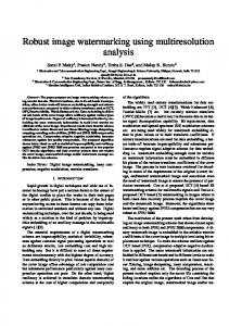
Fig. 8. Metal plates The procedure is as follows, Step 1: Laser spots are cast down onto the top surface of the top plate. Using image differencing, detection and matching process described above, the 2D coordinates of the laser-spot centers on the top surface of the top plate are identified in three CSM cameras.
Fig. 9. Laser spots cast on the top surface of top plate Step 2: The top plate is removed as illustrated in Fig. 10. Therefore, the thickness change of the surface is the thickness of the top plate. Laser spots are cast onto the top surface of the lower plate. The 2D coordinates of the laser-spot centers on the top surface of the lower plate are identified in the same three CSM cameras.
Precise and Robust Large-Shape Formation using Uncalibrated Vision for a Virtual Mold
119
Fig. 10. Laser spots cast on the top surface of lower plate Step 3: After the two sets of laser-spot 2D-coordinate data are stored in computer memory, cue-bearing plates mounted on the robot are introduced into the same physical region as the two stacked plates, as shown in Fig.11.
Fig. 11. Cue-bearing plates approach workpiece Step 4: Newly sampled cues and the joint coordinates of the robot in corresponding poses were used to update, locally, the camera-space kinematics. Then, with the new local mapping model and the two sets of laser-spot 2D-coordinate data in each camera space, the 3D coordinates of surface spots were estimated relative to the nominal world frame. Step 5: The surface points on the top plate are fit to a plane using least squares. The distance from the plane to the surface points on the lower plate are calculated. The average distance is the estimate of the thickness of the removed plate. In step 1 and step 2 the number of laser spots cast on the top surface is varied from 100 to 2000 in various tests. The laser-spot-array direction can be shifted slightly using the pan/tilt unit to cast down new surface spots, allowing for accumulation of a virtually unlimited density of points on the surface regions of interest. A different test consisted of placing multiple paper cues on the top surface of the lower plate, instead of the laser spots, as illustrated in Fig. 12.
120
Computer Vision
Fig. 12. Multiple paper cues on surface The paper cues placed on the surface are the same circular geometry as those borne on the plate mounted on the robot end effector. The 2D coordinates of the cues were identified in three CSM cameras and nominal 3D coordinates of the cues were estimated as the surfacepoint data, which was applied in same process as step 5, in order to calculate the thickness of the removed plate
4. Experiment result and discussion The known thickness of the metal plate is 3.20 mm±0.01mm. The calculated average thickness using about 100 spots (accumulated from multiple images) for estimation is listed in Table 1. Test Number 1 2 3 4 5
Thickness measured (mm) by 100 laser spots vs. 100 laser spots 3.27 3.15 3.21 3.16 3.17
Thickness measured (mm) by 100 laser spots vs. 100 cues 3.28 3.18 3.18 3.25 3.10
Table 1. Experiment result The precision of thickness gauging is consistently within one tenth of a millimeter. It is one order of magnitude higher than image resolution. This sub-pixel level of accuracy was consistent throughout the robot’s workspace, and for a range of plate orientations. Why is the laser-spot-assisted, 3D image analysis able to estimate the CSM target shift with sub-pixel accuracy despite the large random error from the coarse pixel quantization of camera space together with error associated with the 3D-coordinate estimation of laser spots in CSM nominal world frame? An error consists of two parts, deterministic error and random error. The deterministic error was cancelled because the thickness assessment is from the difference of two sets of laser spots, which have the same deterministic offset due to the proximity in distance and continuous mapping of surfaces points in camera space to the same body’s position and orientation. Therefore, only the random error was left in thickness gauging results and the each laser spot’s position assessment is virtually zero-mean. With the advantage of the effect of averaging to filter out the image-discretization and other noise, a large number of laser spots could achieve high certainty and precision. The above experimental result is the proof. The histogram summary of 10 trials is shown in Fig. 13. The data clearly show that the error of thickness gauging is random with normal distribution.
Precise and Robust Large-Shape Formation using Uncalibrated Vision for a Virtual Mold
121
Fig. 13. Histogram of surface points vs. thickness The normal distribution of the random error brings up the issue of level of certainty. The practical question pertaining to this certainty issue is what a sufficient number of laser spots cast on the surface of an object needs to be in order to guarantee each individual assessment is within a certain prescribed precision. In another words, what is a sufficient density of laser spots cast on the surface, in spots per unit area on a flat surface in order to characterize the geometry of the surface with designated accuracy? The variation of the error is measured by standard deviation (STD σ) in statistics. It allows one to deduce the relationship between the number of laser spots (samples) and the certainty of the individual assessment (mean μ) for answering the question. Table 2 shows STD σ of the individual assessments of plate thickness for the five tests. Test Number 1 2 3 4 5 STD of the mean of the 5 tests
Mean (μ) of thickness (mm) with 100 samples 3.27 3.11 3.21 3.12 3.14
STD (σ) of individual assessment of thickness (mm) with 100 samples 0.772 0.7653 0.7383 0.7347 0.7732
0.068
Table 2. Standard deviation of the individual assessments of plate thickness As illustrated in Fig. 14, the individual thickness assessments have about a 68% probability of falling within the range between mean (μ)−STD (σ) and mean (μ)+STD(σ), as expected with a normal distribution.
122
Computer Vision
As presented in [6], consider a random process with standard deviation σ1. A second random process can derived from the first one by taking out m samples (m>1) from the first process and average their values to be a sample for the second process. The samples from the second random process have a standard deviation of σm. The relationship between the σm and σ1 is: σm2 = σ12/m
Fig. 14. Normal distribution of individual thickness assessment In the present case, the predicted (σ100), STD of 100 samples’ mean in the thickness-gauging experiment result, is about 0.07 according to this statistical analysis. The actual STD of the mean of the 5 tests with 100 samples is 0.068, which agrees with the statistical analysis. This relationship was also proven using 2000 spots tests. In the experiment results of Table 2, the third column shows that the same high precision of thickness gauging occurred in the test of placing multiple paper cues on the surface of the lower plate instead of casting laser spots after the top plate was removed. This result proves that there is no significant detection bias between the laser-spot detection and cue detection in camera space. In other words, there is no bias between 2D position of the detected center of cue and laser spot in camera space if they occupy same physical location. (The “physical location” of the laser-spot center is not, strictly speaking, actually defined. What the tests indicate is that, on average, the software places each camera’s camera-space center of a given laser spot in such a way as to represent the same surface juncture in all three cameras.) This seems unsurprising, but thinking how different are the appearances of the cue and laser spot in physical space, there are enough reasons to doubt this no-bias result to warrant physical proof. Among the reasons for a possible bias is the fact that laser spots are incident on the surface from a particular angle, and this angle will vary with any shift in the workpiece or laser-pointer base. The CSM targets established by laser-spot-assisted, 3D image analysis are ultimately for the robot to position the point of interest on a robot’s end effector with high precision. CSM’s high precision is fundamentally based on the premise that a point or juncture attached on the robot end effector collocates the target point in 3D physical space when these two junctures collocate in at least two cameras’ camera spaces. So the non-bias detection of
Precise and Robust Large-Shape Formation using Uncalibrated Vision for a Virtual Mold
123
position between cue and laser spot is a critical premise to extend the CSM high-precision positioning where laser spots are used to establish camera-space targets. In step 3 of the thickness-reduction experiment, cue-bearing plates mounted on the robot were introduced into the same physical region as the two stacked plates. The newly sampled cues and the joint coordinates of the robot in corresponding poses were applied to update local mapping between the camera space object is 2D coordinates and robot joint coordinates. Then, with the new local mapping and the two sets of laser-spot 2D cameraspace coordinates stored in computer memory, the 3D coordinates of surface spots were estimated relative to nominal world frame. Though, in the thickness-gauging experiment, the robot doesn’t need to position its end effector to the target with high precision, in real world applications the CSM targets established by laser-spot-assisted 3D image analysis are used for robot positioning. So the experimental studies of step 3 were performed in same situation as real applications.
5. Summary and conclusion The surface-reduction-gauging experiment proves the ability of laser-spot assisted, 3D image analysis to characterize the geometry of the surface and provide the CSM target with high precision. It also discloses the extent of measurement precision of surface-reduction gauging and reveals the relationship between the density of laser spots cast on the surface, in spots per unit area, to the accuracy of the characterized geometry of surface. The experimental results also prove the following three premises of the surface extent application of laser spots using CSM-based 3D nominal World-frame-coordinate estimation: Though the nominal optical model and nominal robot kinematics model in the CSM system are globally imperfect, the premise is that as long as the laser spots are close enough to each other within the asymptotic-limit region or volume the relative error between them is close to zero-mean. Therefore, any error on the CSM side does not propagate into the measurement of surface reduction relative to an as-located original surface. The experiment repeatedly proves the premise for a range of surface positions and orientations. Another premise is that error in thickness assessment with laser-spot data is unbiased and random. This means that, provided they are matched, a laser-spot center detected in each camera corresponds to one single physical juncture on the object’s surface. In other words, only error in thickness assessment with laser-spot data can be averaged out by applying a large amount of laser-spot data on the surfaces. The results of the above experiment repeatedly verify this premise. There is no bias between 2D position of the detected center of a circular cue and that of a laser spot in camera space if they occupy same physical location. (The “physical location” of the laser-spot center is not, strictly speaking, actually defined. What the tests indicate is that, on average, the software places each camera’s camera-space center of a given laser spot in such a way as to represent the same surface juncture in all three cameras.) High-precision surface-change gauging extends the vision-guided-robot system based on CSM into a more potent surface-operating system, one that in practice only can be done by humans, and this in an imprecise, non-uniform, and often ineffective way. A number of surface-finishing tasks entail application of force or pressure combined with in-plane motion in order to achieve a scrubbing, polishing or sanding effect. Such tasks often make use of human dexterity and effort, which can result in repetitive-motion injury and incomplete or uneven treatment of the surface. But with high-precision surface reduction gauging and
124
Computer Vision
CSM, our vision-guided robot system can accomplish these tasks efficiently and uniformly. Material removal can be monitored and surface reduction gauged and controlled to within approximately one tenth of a millimeter.
6. References Steven B. Skaar and Guillermo Del Castillo Revisualizing Robotics: New DNA for Surviving a World of Cheap Labor, 2006. González-Galván E.J., Loredo-Flores A., Cervantes-Sanchez J.J., Aguilera-Cortes L.A., Skaar, S.B., “An Optimal Path-generation Algorithm for Surface Manufacturing of Arbitrarily Curved Surfaces using Uncalibrated Vision”. Robotics and ComputerIntegrated Manufacturing. Vol. 24, No. 1, pp. 77-91. 2008. Zhang, Biao. Three-dimensional laser-assisted image analysis for robotic surface operation with camera-space manipulation. Ph.D. Dissertation. University of Notre Dame. 2007. Gonzalez-Galvan E.J., Pazos-Flores F., Skaar S.B., Cardenas-Galindo A., “Camera Pan/Tilt to Eliminate the Workspace Size/Pixel-Resolution Tradeoff with Camera-Space Manipulation”. Robotics and Computer-Integrated Manufacturing, 18(2), Elsevier Science Press, pp. 95-104. 2002. Gonzalez-Galvan,E.J., Skaar,S.B., Korde,U.A., Chen,W.Z. “Application of a Precision Enhancing Measure in 3-D Rigid-Body Positioning Using Camera-Space Manipulation” The International Journal of Robotics Research ISSN 0278-3649. Vol. 16, No.2, pp.240-257. 1997. Dietrich C., Uncertainty, Calibration and Probability: The Statistics of Scientific and Industrial Measurement, 2nd edition. Page 29, CRC Press, January, 1991.