Nov 18, 1994 - Rockwell Automation,. Allen-Bradley Company, Inc,,. Milwaukee, Wl 53204. Prediction of Solder Joint. Geometries in Array-Type. Interconnects.
Prediction of Solder Joint Geometries in Array-Type Interconnects S. M. Heinrich Department of Civil and Environmental Engineering,
M. Schaefer Department of Mechanical and Industrial Engineering Marquette University, Milwaukee, Wl 53233
S. A. Schroeder Science Center, Rockwell International Corporation, Thousand Oaks, CA 91358
P. S. Lee Rockwell Automation, Allen-Bradley Company, Inc,, Milwaukee, Wl 53204
An approximate mathematical model is developed for predicting the shapes of solder joints in an array-type interconnect (e.g., a ball-grid array or flip-chip interconnect). The model is based on the assumption that the geometry of each joint may be represented by a surface of revolution whose generating meridian is a circular arc. This leads' to simple, closed-form expressions relating stand-off height, solder volume, contact pad radii, molten joint reaction force (exerted on the component), meridian curvature, and solder surface tension. The qualitative joint shapes predicted by the model include concave (hourglass-shaped), convex (barrel-shaped, with a truncated sphere as a special case), and truncated-cone geometries. Theoretical results" include formulas for determining the maximum and minimum solder volumes that can be supported by a particular pair of contact pads. The model is used to create dimensionless plots which summarize the general solution in the case of a uniform array (i.e., one comprising geometrically identical joints)for which the contact pads on the component and substrate are of the same size. These results relate the values of joint height and width (after reflow ) to the solder joint volume and the molten-joint force for arbitrary values of the pad radius and solder surface tension. The graphs may be applied to both upright and inverted reflow, and can be used to control standoff for higher reliability or to reduce bridging and necking problems causing low yields. A major advantage of the model is that it is numerically efficient (involving only simple, closed-form expressions), yet generates results that are in excellent agreement with experimental data and more complex models. Thus, the model is ideally suited to performing parametric studies, the results of which may be cast in a convenient form for use by practicing engineers. Although in the present paper the array is assumed to be doubly-symmetric, i.e., possess two orthogonal planes of symmett T, the model may be extended to analyze arrays of arbitrary layout. The motivation for predicting joint geometries in array-type interconnects is twofold: (1) to achieve optimal joint geometries from the standpoint of improved yield and better reliability under thermal cycling and (2) to take full advantage of the flexibility of new methods of dispensing solder, such as solder-jet and solder-injection technologies, which enable the volume of each individual joint to be controlled in a precise manner. Use of dispensing methods of these types permits the solder volumes in the array to be distributed in a non-uniform manner. Results such as those presented here (in combination with appropriate fatigue studies) can be used to determine the optimal arrangement of solder volumes.
Introduction A common means of attaching an integrated circuit chip or chip carrier to a substrate is to deposit or attach solder to an array of contact pads on the chip and/or substrate prior to reflow. Examples of technologies implementing array interconnects include flip-chip (controlled-collapse) and ball-grid array (BGA). As with any solder interconnect, the two major areas of concern for array-type interconnects are yield and reliability. Defects which adversely affect the yield of a soldering process are related to solder joint geometry: opens and bridges. From a reliability standpoint, joint geometry also has an impact on the fatigue life of the assembly during thermomechanical loading. Thus, the ability to predict and control the individual joint geometries in the array is critical to obtaining robust and reliable A modified version of "Prediction of Solder Joint Geometries in MultipleBump Arrays," presented at the ASME Winter Annual Meeting, Symposia on Materials and Mechanics in Electronic Packaging, Chicago, IL, November 1318, 1994. Contributed by the Electrical and Electronic Packaging Division for publication in the JOURNAL OF ELECTRONICPACKAGING. Manuscript received by the EEPD January 1996; revised manuscript received April 1996. Associate Technical Editor: John Lau.
114 / Vol. 118, SEPTEMBER 1996
designs of interconnects. Models for predicting geometries in multiple-joint arrays are especially important, because of the many parameters that influence the final joint shapes. For instance, in theory each individual solder joint in a 15 × 15 array could be designed to be of a different size and shape such that the reliability of the total package is optimized. In fact, highspeed dispensing methods, such as solder-jetting (Wallace, 1989; Choi and Delcofio, 1990; Hayes et al., 1992) and injection techniques (Tsukada et al., 1993 ), may make such sophisticated designs a reality in the future. Hence, one must be able to specify appropriate values of the many parameters involved in the design and processing of the interconnect. Previous Studies. The prediction of solder joint geometries in array-type interconnects has received significant attention in the literature. In 1969 Goldmann utilized a truncated-sphere model for predicting joint geometry and used it to optimize the mechanical reliability of controlled-collapse joints. Similar studies were presented in the 1980s (Ohshima et al., 1982, 1985; Satoh et al., 1983, 1987), in which three joint geometry models were discussed briefly: the truncated-sphere model, the arc-revolution model, and an "exact" axisymmetric model utilizing Runge-Kutta integration of the Laplace-Young equation.
Copyright © 1996 by ASME
Transactions of the ASME
Downloaded From: http://electronicpackaging.asmedigitalcollection.asme.org/ on 12/19/2013 Terms of Use: http://asme.org/terms
(ii)
Recently, Lee and his co-workers have developed more sophisticated three-dimensional models that incorporate initial misalignment, so that the realignment mechanism, critical in optoelectronic applications, may be modeled accurately (Landry et al., 1991; Patra and Lee, 1991; Patra et al., 1992; Ju et al., 1993). In their model the governing differential equation was integrated numerically, assuming that each horizontal crosssection of the misaligned joint is circular. Results based on a Rayleigh-Ritz approach were presented by Katyl and Pimbley (1992) and Nigro et al. (1993). Recently, a general-purpose program called the Surface Evolver (Brakke, 1994), which predicts minimum-energy configurations of capillary surfaces, has been applied by Singler et al. (1995) to a single bump- or balltype joint of specified height.
Objectives of the Study. The purpose of this paper is to present a simple joint geometry model based on the assumption that the geometry of each joint in the array may be described by a surface of revolution whose generating meridian is a circular arc. This circular-arc, or arc-revolution, model was proposed by Ohshima et al. in 1982; however, details of their model were not provided, and the fundamental relationship relating the various geometric parameters of the joint was presented in integral form. In this paper a circular-arc model involving explicit, closed-form expressions will be developed. This enhances the numerical efficiency of the resulting computer program and also permits insight into the interplay among the various parameters of the problem. The model assumes that the array layout is doubly-symmetric, i.e., it possesses two orthogonal planes of symmetry. Otherwise, variations in solder joint volume, pad radii, and solder alloy are arbitrary throughout the array. Despite the attention that the prediction of joint geometries in array-type interconnects has received in the past, numerical results of a general nature are difficult to find in the literature (Heinrich, 1994). Since the circular-arc model is relatively simple and, thus, numerically efficient, it is well-suited to performing parametric studies and encapsulating the results in the form of dimensionless design aids. With this in mind, a second objective of this paper (in addition to the description of the mathematical model) is to apply the model to the special case of a uniform array (i.e., one comprising geometrically identical joints) having equal pad radii on component and substrate, and summarize the results in dimensionless plots relating joint height and width to solder joint volume, for arbitrary values of component weight, number of joints, contact pad size, and solder surface tension.
(iii) (iv)
(v) (vi)
the contact pads on the component and substrate are circular and are perfectly aligned at the time of solidification; the free surface of the molten joint is axisymmetric; the meridian defining the joint's free surface is approximated by a circular arc, an assumption that is justified by experimental observation of flip-chip and ball-gridarray joints; the contact pads are completely covered by solder, but the solder does not spread beyond the pads. the contact pad metallization is assumed to be perfectly wettable, while the surrounding solder resist material is perfectly non-wettable, i.e., the static receding and advancing contact angles at the edge of the contact pad are assumed to be 0 and 180 deg, respectively.
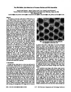
The following geometric parameters describing the joint shape are shown in Fig. 1 (a): h = joint height or stand-off height; rl, r2 = radii of contact pads on substrate and component, respectively; ro , zo = coordinates of center of curvature of circular-arc meridian; R = radius of curvature of circular-arc meridian; V = volume of solder joint; 01, 02 = contact angles on substrate and component, respectively. Clearly, for fixed values of rl, r2, and height h, the radius R (and, in fact, any geometric parameter of the joint) depends only on volume V. Moreover, these relationships are strictly geometric. The relevant geometric expressions will now be derived. Non-dimensionalizing all quantities using height h as a scale factor, the following dimensionless parameters may be defined:
(i)
the molten solder joint has attained static equilibrium when solidification occurs;
Journal of Electronic Packaging
P2 = r2/h,
(lb)
Po = ro/h,
(lc)
to = zo/h,
(1 d )
K = R/h,
(le) (l f )
V / h 3.
Referring to Fig. 1 (b) the meridian's center of curvature (Po, to) may be related to the radius of curvature R and the pad radii pl and p2. For a given value of R, however, there exist two possible centers of curvature, depending on whether the joint shape is concave ( "hourglass-shaped" ) or convex ( "barrel-shaped"). Simple geometry leads to the following expressions: 1 [ ~/( P0 = ~ Pl + P2±
4K 2 1 - 1 , Pi - P2) 2 + 1
t 0 = ~ 1 1 1 ± ( p ~ - p 2 ) ~ ( p ~ - p4/~2 2) 2+ 1
Joint Geometry Model Single-Ball Model. Prior to developing a model for predicting the joint geometries in an array-type interconnect, the relationship between the joint geometry and the force exerted by the molten joint on the component must first be established for a single joint. The assumptions on which the single-ball model are based include the following:
(la)
ff =
Organization of the Study.
Closed-form expressions relevant to a single solder joint will first be derived. An algorithm will then be proposed for using these formulae to create a Single-Ball Module (SBM) that relates the force on an individual bump- or ball-type molten joint to the joint height. Once this has been accomplished, the algorithm for the Multiple-Ball Module (MBM) will be presented. The MBM uses the SBM iteratively until the height is determined at which all joint forces balance the component weight. Dimensionless design aids will then be generated by applying the MBM to the problem of a uniform array for which the contact pads on the component and substrate are of equal size.
Pt = r l / h ,
(2a)
11' (2b)
where the upper (lower) signs in Eqs. (2a, b) (and in all dualvalued equations that follow) correspond to a concave (convex) profile. The equation of the circular-arc meridian may be written as
p(~)
= p0 -7 ~R ~ -
(4 -
~0)2,
(3)
SEPTEMBER 1996, Vol. 118 / 115
Downloaded From: http://electronicpackaging.asmedigitalcollection.asme.org/ on 12/19/2013 Terms of Use: http://asme.org/terms
d
CO
"~
h=r 8ubstrate Pad
r1
1P
j
~olume ~
pl J
J
"11
(a)
(b)
Fig. 1 Geometricparameters:(a) dimensionalform; (b) dimensionlessform which may be integrated to yield an expression for the joint volume: gg = ~-
f01
[p(~)l~d~
{
= zr g ~ - ~g + ~0 -
1/3
+ Po[P2 + ~o(Pl - P2)]
where 0 -< cos-~ (
)~zr.
(Pappus' Second Theorem (e.g., Shanks and Gambill, 1973) may be employed in lieu of the integration.) For given values of Pl and Pz, Eq. (4) (in conjunction with Eqs. ( 2 ( a ) , (b)) relates dimensionless volume 9 to dimensionless radius/~. Note that this relationship is dual-valued, i.e., for each value of E, there exist two different volumes. The smaller (larger) volume corresponds to the upper (lower) signs in Eqs. (4) and ( 2 ( a ) ( b ) ) and to a concave (convex) joint. For the special cases in which the joint takes the shape of a truncated cone or a circular cylinder, Eq. (4) may be replaced by its appropriate limiting value: 71"
r d J t ~ = -~(P~ + P,P2 + P~),
1 /~min = ~ [ ( P l -- P2) 2 "{" 1].
(6)
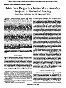
Concave profiles having K = Emin are on the verge of receding from the edge of the larger pad, whereas convex profiles with this minimum radius of curvature correspond to impending spreading beyond the smaller pad. These two limiting profile shapes are illustrated in Fig. 2. ,Associated with these shapes are the minimum and maximum solder volumes that may be supported by a pair of pads, without receding from or spreading beyond the pad edges. Useful expressions for these limiting volumes may be determined by evaluating Eq. (4) at E = Rm~,, which is defined by Eq. (6). For equal pad sizes, these expressions reduce to the following:
(6
-F p l 2 --T- ~
116 / Vol. 118, SEPTEMBER 1996
Pl
sin 02 ---- "q- PO g-- /92
•
(7)
(8)
The circumferential radius of curvature is defined as the distance between the surface and its axis of revolution, measured along the normal to the surface. From Fig. 3 the dimensionless circumferential radius of curvature at the component level is seen to be P2 = Pz Ec = sin (Tr - 02) sin 02 '
(5a)
Due to the physical constraint that the molten solder cannot penetrate the solid component and substrate materials, a minimum value of E may be calculated from geometry:
Vmi./maxlpt=p2 = ~
Note that although Eq. (7) provides geometry-based upper and lower bounds on V, instabilities in the molten solder configuration could occur for dimensionless solder volumes greater than (less than) the value of ~min (gmax) given by Eq. (7). Such instabilities are not included in the current model; they can best be addressed by appealing to an energy minimization approach, such as is implemented by Singler et al. (1996) who use the Surface Evolver code (Brakke 1994) to model solder bridge stability. Two other geometric parameters of interest are the contact angle 02 (between the free surface of the solder and the contact pad on the component) and the circumferential radius of curvature of the solder surface at the component pad. These are important quantities since they determine the vertical reaction force exerted by the molten joint on the component. A straightforward geometric calculation leads one to the desired relationship for 02:
(9)
where sin 02 is given by Eq. (8). Now that the relevant geometric expressions have been derived, the force F exerted by the molten solder joint on the component may be related to the geometric parameters of the joint. This force consists of two portions: one due to surface tension and the other associated with pressure, and may be calculated as follows (Fig. 4): F = - [ y sin (Tr - 02)](27rr~) + p(zrr~),
(10)
where y is the surface tension associated with the molten solder and the surrounding atmosphere or flux, and a positive value of F represents a compressive force. The (gage) pressure p exerted on the component may be determined by applying the Laplace-Young equation (Klein Wassink, 1989) to the free solder surface where it meets the component:
p
~ -v-~+
~
=-Y( l h w-~+ sin02/P2/'
-v- R
(11)
Transactions of the ASM~ /
/
Downloaded From: http://electronicpackaging.asmedigitalcollection.asme.org/ on 12/19/2013 Terms of Use: http://asme.org/terms
¢
I
% "
m
In
|m
=p
=p
(a) Fig. 2
(b)
Limiting profiles corresponding to minimum radius of curvature of meridian: {a) concave; (b) convex
Substituting Eq. (11 ) into Eq. (10) and utilizing Eq. (8) yields a formula for the dimensionless force between the molten joint and component: F-=-
F yh
= V-
~Tpop2 R
(12)
'
added joint is less than that given by Eq. (14b), the stand-off will decrease. Since the expression for the force (Eq. (13)) is indeterminate for/~ ~ oo (truncated cone), the appropriate limit may be taken for this special case, resulting in P2
or, eliminating Po using Eq. (2a),
F=~[¥(p,+p2)-~(p~
_4j~2p2)2 +
1 -1].
F[.~
(13)
Eq. (13) implies that, for concave joints (upper sign), the force is always negative, i.e., in tension. Also, for a convex joint there exists a particular value of g (and thus 17) for given p~, P2 such that the force on the molten solder is zero: RI F=o
= ½~/[(Pl +
P2)z +
1][(pl - p2) 2 + 1]
?T
Wit=0 = g [1 + 3(p~2 + p~)]
(convex), (convex).
(14a) (14b)
Eq. (14(b)) may be obtained by substituting Eqs. (14(a)) and (2(a), (b)) into Eq. (4), employing the lower signs in these equations. The fact that Eq. (2(a)) yields P0 = 0 for the zeroforce case indicates that the meridian's center of curvature lies on the axis of revolution. In other words, the joint geometry corresponding to zero force is simply a truncated sphere (which is the exact shape if solder self-weight is neglected). Expression (14(b)) enables one to ascertain the effect of adding one or more joints to an existing design for which stand-off h and pad radii r~ and r2 are known. If the volume of an added joint exceeds the zero-force value given by Eq. (14b), it will contribute an extra compressive force to the component, thereby increasing the stand-off height. Conversely, if the volume of the
= -~-
~/(pl -
(15)
p2) 2 +
1 '
The formulae derived in this section enable one to create a "Single-Ball Module" (SBM) capable of calculating force F for an input height h, provided that the parameters (r~, r2, V, TT) are known, which is usually the case. For an input height h, the correct radius of curvature R and profile type (concave, convex, or truncated cone) are determined by iterating until the joint volume matches the specified volume. The details of the SBM algorithm are shown in the flow chart of Fig. 5. To determine the correct joint height, the entire array must be considered, since the equilibrium height is that for which the component weight is balanced by the sum of all the individual joint forces. In the next section an algorithm will be presented for the "Multiple-Ball Module" (MBM), which will use the SBM iteratively to determine the height h and individual joint geometries for a given array and component weight. Although the results of this section stem from a simple model predicated on the geometric assumption of a circular-arc meridian, the model may be interpreted in the context of an "exact" formulation of the problem. The governing equation of the exact equilibrium configuration of the solder surface may be expressed as (e.g., Heinrich 1994) [ p ( z ) = po + v
1 Rx(z)
+
1
]
(16)
R2(z-----~ '
where p(z) is the pressure within the molten solder at height z, p, is the (uniform) atmospheric pressure, and Rl(z), R2(z) are the principal radii of curvature of the solder surface at height z. The assumption of a circular-arc meridian causes the righthand side of Eq. (16) to differ from its exact value, i.e., the
Component
+
p Fig. 3 Definition of dimensionless circumferential radius of curvature Rc
Journal of Electronic Packaging
Fig, 4
Forces exerted by molten solder joint on component
SEPTEMBER 1996, Vol. 118 / 117
Downloaded From: http://electronicpackaging.asmedigitalcollection.asme.org/ on 12/19/2013 Terms of Use: http://asme.org/terms
lun llUnllnlln
llll~llnnllUll
InUllUU
J.(I).(i) Inputv(I).,(I) W, N "1 ' ' 2 '~ I-,1, 2 ..... N '--
Input
J rl,r=,V,Y I
= w mi m n
J
m = a u = m n u m u e
'l~t-~mln(6)
F(1), i-1,2 ..... N
Increase h
--L Non-Equilibrium'14,1--'-I:1~'(I). W Fig. 5 Flow chart depicting h o w Single-Bail Module (SBM) relates joint force F to joint height h. Relevant equation numbers are in parentheses. W h e r e dual signs appear in an equation, " U " and "L" denote upper and lower signs, respectively.
internal pressure p (z) differs from the exact (hydrostatic) distribution by some "residual" load distribution. This residual internal pressure may be interpreted as arising from a non-uniform density of the liquid solder. Since the approximate configuration has been observed (both experimentally and numerically) to be an excellent approximation to the exact shape, this residual pressure is relatively small. Multiple-Ball Model. In the development of the multipleball model the following assumptions are made: (i)
(ii) (iii)
The array has a "doubly-symmetric" layout, i.e., the layout possesses two orthogonal planes of symmetry (Fig. 6); The center of gravity of the component is aligned with the center of the array; No spacers are used to actively control stand-off height, i.e., the component weight is supported solely by the reflowed joints.
Assumptions (i) and (ii) imply that the component will settle uniformly during reflow such that all joints have the same
Output
h, r(01! z(01),R(I) F(I ) i-1, 2, .... N Fig. 7 Flow chart depicting h o w Multiple-Ball Module (MBM) utilizes Single-Ball Module (SBM) to predict joint forces and joint shapes
height. (Non-symmetric arrays could result in a tilted component after reflow.) Note that solder volumes, pad dimensions, and surface tension (dictated by solder alloy, flux type, etc.) may vary arbitrarily within an array, provided that the array is doubly-symmetric. This permits process and design engineers a great deal of flexibility in engineering an array interconnect using the MBM. The SBM described in the previous section may be easily incorporated into the Multiple-Ball Module by iterating on the height h of the array until the sum of all joint reaction forces on the component balances the component weight W: N
W - ~ F ~;) = 0,
(17)
i=1
e@e
• oOo • ....
. . . .
"**" •
Oo o
Fig. 6 Example of doubly-symmetric array layout
118 / Vol. 118, SEPTEMBER 1996
where N is the total number of joints in the array and superscript (i) denotes a quantity associated with the ith joint. Component weight is considered positive for a standard reflow operation, i.e., when the component is attached to the upper side of the substrate. A negative weight is specified for inverted reflow, i.e., when the component hangs from the substrate's lower surface. The initial value of height used in the iteration is hm~,,, defined as the smallest height for which none of the joints would spread beyond a pad. The value of h is increased in the MBM until equilibrium is achieved. A flow chart for the MBM is shown in Fig. 7. Input parameters to the MBM are the component weight, number of joints in the array, and the pad dimensions, surface tensions, and solder volumes for each joint in the array. Output parameters include the individual joint forces and
Transactions of the ASME
Downloaded From: http://electronicpackaging.asmedigitalcollection.asme.org/ on 12/19/2013 Terms of Use: http://asme.org/terms
|
)
(WeightW) : -2
/SOLDER ; [BUMP I
'~ -1
g/vr = 0 I 2 3
) UBSTRATE
w/2
i '=-
)
I
Fig. 8 Typical reflowed joint in uniform doubly-symmetric array with equal pad radii
V/r**3
the following geometric parameters: (h, r0(j), Z(oi~, R(i~), i = 1, 2 . . . . . N. Note that these geometric quantities completely characterize the shapes of all the solder joints in the array. Thus, any geometric quantity of interest (e.g., maximum width of reflowed joints) may be derived from the output data.
(a)
3 2 1
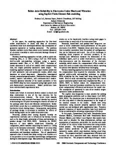
Numerical Results and Discussion Although the multiple-ball model presented in the previous section may be applied to any doubly-symmetric array of bump/ ball-type joints (without spacers), the results presented herein will be limited to the case of a uniform array for which the contact pad radii on component and substrate are assumed to be identical (Fig. 8). (In other words, the pad radii, solder joint volumes, and solder alloy do not vary throughout the array.) In this case of practical interest all molten joints will share the component weight equally and therefore have the same geometry, so that the results may be generated by applying the MBM to a single joint supporting a force of magnitude W/N. In order for the results to be of general use, they will be presented in dimensionless form, with all length quantities being scaled by the pad radius r. The complete solution to this problem is summarized in Fig. 9 for both upright ( F > 0) and inverted ( F < 0) reflow. The results in Fig. 9 ( a ) enable one to relate the stand-off height to the solder volume and the force per molten joint ( F = W / N ) . Since stand-off height has a strong influence on the shear strain in the solidified joint under thermomechanical cycling and, hence, on fatigue life, the ability to predict and control this parameter is critical to improving the reliability of the interconnect. From the standpoint of improving the yield of a reflow operation, the graphs in Fig. 9(b) may be used to select the spacing between joints to minimize bridging problems. Parameter w in the figure is defined to be the width of the joint at mid-height (see Fig. 8), which represents the diameter of the largest section for a convex joint or the diameter of the smallest section for a concave joint. If the joints are convex, or "barrel-shaped" (always the case for upright reflow), the value of w will exceed the pad diameter, in which case the center-to-center spacing of the joints must be greater than w to prevent bridging. An inverted reflow process may also result in barrel-shaped joints (w > 2r ) if F~ y r < - 7r. (This is suggested by the curves in Fig. 9(b) and may be proven by setting p, = p2 in Eq. (13) and taking the limit as R ~ ~ , or by directly calculating the resultant force at the top of a circular cylindrical molten joint.) The locations at which the curves end abruptly in Fig. 9 also provide some important information with regard to yield. For example, the end points of the curves labeled " F / y r = 4 " and " F / y r = 5" (upright reflow) correspond to solder joints on the brink of being squeezed outward beyond the pad edges. On the other hand, the end points of the " F / y r = - 4 " and " F / y r = - 5 " curves (inverted reflow) may be
Journal of Electronic Packaging
FIyr = 0 .I .2
0
S
10
15
V/r**3
(b) Fig. 9
Dimensionlessplotsrelating(a)jointheighthand(b)jointwidth
w (at mid-height) to joint volume V for a uniform array with equal contact p a d s . ( r = pad radius; F = W/N = force carried by each molten joint; W = component weight, positive for upright reflow, negative for inverted reflow; N = n u m b e r o f joints in array; 3' = surface tension of molten solder,)
interpreted as unstable inverted configurations, i.e., a solder volume greater than the end point value would be incapable of providing the necessary resisting force, and the component's weight would cause it to pull away from the substrate. As a practical matter, one would avoid these critical situations by employing sufficiently large factors of safety in the design of the interconnect. Useful closed-form mathematical expressions may be derived for the zero-force curves in Figs. 9a and 9b. Setting Pl = pz = r/h and V = V/h 3 in Eq. (14(b)) gives the equation of the zero-force curve in Fig. 9 ( a ) : r~ - 6
+ 6
.
(18)
A simple identity relating joint height to joint width for the case of zero force and equal pad radii may be derived by recognizing that w = 2(ro + R)
(19)
SEPTEMBER 1996, Vol. 118 / 119
Downloaded From: http://electronicpackaging.asmedigitalcollection.asme.org/ on 12/19/2013 Terms of Use: http://asme.org/terms
Table 1
Comparison of joint heights predicted by various models. (Results of present study listed in parentheses.) rl (mm)
r2 (mm)
Lin (1994)
.1
Katyl&Pimbley (1992)
.072
Model
V (mm3)
flsolder (g/era3)
"Y (dyne/era)
F (dynes)
h (mm)
.1
.00314
0
400
5.5
.060
.001214
11.4
430
19.453
.0853 (.0853) .0578 (