Fault Detection in Air-Handling Units. A.S. Glass, P. Gruber, M. Roos, and J. Todtli he feasibility of a qualitative approach. T for detecting faults in an air-condition ...
QualitativeModel-Based Fault Detection in Air-Handling Units A.S. Glass, P. Gruber, M. Roos, and J. Todtli
T
he feasibility of a qualitative approach for detecting faults in an air-conditioning system is considered. The system considered is a multi-zone variable air volume air-handling unit, and the faults investigated include types which result in deterioration of operation, as distinct from actual failure. The operating modes of the sequential controller for the central air-handling plant can be matched to a corresponding qualitative classification of steady-state temperatures. Observed mismatches indicate the presence of faults. Trials of the method in an air-conditioning test laboratory are reported.
HEATING COOLING COIL COIL
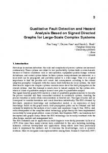
Introduction This article extends and consolidates the investigations reported by Fomera et al. [ 11 and Glass [2], in which a qualitative approach to detecting a class of faults in a Fig. 1. The simplified reference air-handling system. variable air volume air-handling system The qualitative detection method described presupposes the was developed. The qualitative approach identifies certain socalled “landmarr* of the regulating a central temperatures and control settings of the central air handling unit air-handling unit and relates them to conesponding “landmarks” (CAHU) to be quasi-stationary, Consequently a class of prototype steady-state detectors has been developed and implemented of the relevant air temperatures and flows. in a fault detection system in the simulation model. Furthermore, Using this approach, a wide class of operating faults can be it has been tested on a laboratory heating, ventilation, and airanalyzed. In particular, we deal with faults which result in conditioning plant (HVAC plant). A theoretical analysis of the deterioration of operation as distinct from actual failure-a situthreshold problem for various designs of a steady-state detector ation known to occur frequently in practice. Conflicts between (SSD) is discussed by Tiidtli and Gruber 131. qualitativevalues of the controller states as actually observed and those expected-as derived from the measured qualitative temDescription of the Test System perature states-provide evidence of such faults. Simulation tests have been carried out using a SIMULINK This a for analyzing the model of a simplified variable ak-volume system (VAV system) expected to result from given faults, and by applying this aP- based on the Annex 25 reference &-handling system described Preach to known faults, a rule-table Can be compiled to aid by Kelly [4] (SIMULINK is acomputer simulationenvironment, diagnosis. part of the MATLAB software package supplied by The MathWorks Inc.). The system comprises a controlled central air-hanAn earlier version of this article was presented at the 3rd IEEE ding unit supplying air to three independently controlled zones Conference on Control Applications, Strathclyde University, Glas- with differing loads. Both the reference system and the simplified gow, Aug. 24-26,1994. Three of the authors, A S . Glass, P.Gruber version are described in more detail in Fomera et al. [ 131. We and J . Todtli, are with Lundis & Gyr Corp.,CH-6301 Zug, Switzer- summarize the components and control strategy of the simplified land. M . Roos is with the Institutefor Structural Engineering, Swiss system below. Federal Institute of Technology,CH-8193 Zurich, Switzerland. The research described in this article was partially funded by rhe Swiss The Component System Federal Energy Ofice (Bundesamtfur Energiewirtschaf) and the The overall system under test is illustrated in Fig. 1. It consists Swiss National Foundation (Schweizerische Nationalfonds), to of a central air-handling unit, depicted in Fig. 2, supplying air to whom we are gratefilly indebted. a number of separately controlled zones. The CAHU comprises
August 1995
0272- 1708PSl$O4.o001995IEEE
11
a bypass mixer and a heating coil followed by a cooling coil in a single air duct. The bypass dampers are controlled to provide a mixture of outside air and recirculated air; the amount of outside air may vary between 20%and 100% of the maximum airflow through the CAHU. The air for each of the three zones is processed through a VAV box containing a damper and a reheating coil. The airflow to each zone as regulated by the damper may vary between 40% and 100%of the specified maximum. In point of fact, the maximum flow from the CAHU is not sufficient to provide maximum flows through all three zones simultaneously, so limiting effects can be expected to occur. The system illustrated differs from standard North American practice in not including dehumidification of the cooling coil. However, the qualitative fault detection technique described below can also be applied to some such systems. The Control Strategy of the System Three controllers share the task of regulating the fans, dampers, heating coils, and cooling coils so as to attain the required temperatures and airflows in each of the three zones. Referring to Fig. 1, Controller C1 regulates the CAHU and attempts to maintain the supply air temperature Ts at its set point by operating the preheating coil, dampers, and cooling coil in sequence. Controller C2, which regulates a single zone, attempts to maintain the zone temperature Tz at its set point by operating in sequence the damper and reheating coil in the VAV box. The third controller is an idealized “flow control” goveming the airflow through the CAHU and the various zones. It ensures that the flows m,, , mZ2,and m,, meet the requirements set by the zone controller
C2, provided the resulting total airflow m through the CAHU does not exceed its specified maximum. If the CAHU aifflow maximum is reached, the total flow is shared among the three zones in proportion to their respective requirements. The Central Air-Handling Unit The fault detection methods described below are applied specifically to the CAHU. As mentioned above, its task is to supply air at a controlled, fixed temperature Ts by operating the preheating coil, dampers, and cooling coil in sequence. The corresponding outputs of Controller C1 are denoted UH,UD,and Uc, respectively. The controller also includes an economy control feature, in which the control action on the bypass is reversed whenever the outside air temperature TOAexceeds the return air temperature. As mentioned, this system does not provide for dehumidifcation. If, however, the temperature control in such a system operates as described above, and the humidity control only operates while the cooling coil is in operation, then the fault detection method described below can be applied. The overall system, including the zones, affect the CAHU indirectly. The VAV boxes, acting in response to any loads in the zones, determine overall air flow m, while the retum air temperature TRresults from mixing the air extracted from the zones. Thus, controller Ci must respond to three quantities over which it has no control, TOA,TR,and m,which can be formally regarded as disturbances in this control loop.
12
The QualitativeModel-Based Fault Detection Method The detection method described below involves reducing measured controller outputs to qualitative values and at the same time using temperature measurements to predict expected qualitative controller outputs in steady state. This procedure necessitates reliable steady-state detection. Although we classify faults in terms of observed discrepancies using rule tables, such rules are derived analytically from the models as distinct from empirical data. Thus our fault detection method incorporates a modelbased approach. The Fault Detection and Diagnosis Strategy The current fault-detection strategy relies on analyzing the steady-state behavior of the system, including controls. Our objective has been to identify qualitative modeling methods that can lead to successful fault detection and diagnosis procedures (FDD procedures). Qualitative models are investigated because, even if conventional quantitative mathematical models are available for the system components, it is frequently impracticable if not impossible to obtain all of the relevant physical parameters of the system. Thus FDD methods based on qualitative models are particularly robust. Obviously, there is a tradeoff in that the same methods are often less sensitive and therefore may not be able to detect faults in all operating states of the system. Furthermore, they may not be able to discriminate between different types of fault. One of the goals of this work was to assess the circumstances under which it is possible to detect given faults in a CAHU using qualitative information. The strategy adopted corresponds to the general scheme described in Fomera et al. [l]. The overall structure of such a qualitative model-based fault detector is shown in Fig. 3. This conforms to the structure of the so-called general diagnostic engine (de Kleer & Williams [ 6 ] ,Dexter & Glass [7]). The fault detector models we consider are also related to the generic FDD scheme proposed by Rossi and Braun [8]. From the central air-handling unit the measured values of the temperatures TOA,TR,Ts and the control variables UH, UD, Uc are obtained and fed into the first stage of the analog pre-processor, which serves to test whether the system is in steady state. ~~
Relief Air
MIXING
DAMPERS
fi
RETURN FAN
i
i *...
HEATING COOLING COIL COIL
ig. 2 . The central air-handling unit.
IEEE Control Systems
In point of fact, the method involves quantitative pre-processing of temperature data, but particular stationary states are identified in which the qualitative settings of the control signals (“minimum,” “maximum,” or “between”) betray the presence of faults. This differs from the type of purely qualitative formalism in which, for instance, all physical quantities, such as temperatures, etc., are strictly described in terms of intervals.
U:E (MINO, BETW, MAXO DISCREPANCIES?
U:s
(CLO. NCLO)
I
Fig. 3 . The qualitative model-basedfault-detection strategy.
Refemng to the left half of Fig. 3, the controller outputs are converted to qualitative values Us, Ux , and Us. In the right half of the figure, the temperature data is input to a model-based predictor which outputs , and CS, the expected qualitative controller states under steady-state conditions. The qualitative values of the outputs of the transformation and predictor blocks are chosen from the following sets:
e$,
Table 1. Qualitative States of the CAHU Sequential Controller
U s E {CLO, NCLO},
U$
Heating Coil Bypass Dampers
(1)
I
63E {CLO,NCLO}, 68E {MINO,BETW, MAXO), 68E {CLO,NCLO}, (2)
where the linguistic mnemonics “CLO,” “NCLO,” “MINO,” “MAXO,” and “BET%’” stand for “closed,” “not closed,” “maximally open,” “minimally open,” and “between,” respectively. Faults are detected on the basis of discrepancies between the measured qualitative controller outputs and the corresponding model-based predictions based on temperature measurements.
August 1995
Controller outputs to ...
Qualitative Controller State
E {MINO,BETW,MAXO},
us E {CLO,NCLO},
Transition States of the CAHU Controller The strategy hinges on analyzing the transition states of the sequential controller regulating the CAHU. One transition occurs when the controller switches from operating the heating coil to operating the bypass dampers; a similar transition occurs when the controller switches from the bypass dampers to the cooling coil. A third transition occurs when the controller switches into economy mode and reverses the direction in which the dampers are operated. These transitions correspond to the idea of landmarks used in some approaches to qualitative physics (Kuipers, [9,10,11]; Dexter & Glass, [7]). Landmarks are physical values of special significance. For example, freezing and boiling temperatures can serve as landmarks because phase transitions occur. The values taken by qualitative variables can either be on one of the landmarks themselves or in an interval between two landmarks. In our case, neglecting the issue of economy control for the time being, we identify five qualitative values of the CAHU controller states, depicted in Table 1. An equivalent classification occurs when the system goes into economy mode, the only difference being that Xmax and Xmin should be interchanged in the above table. The two landmark controller transition states can be simply related to corresponding critical temperatures. Given a particular flow h,supply air temperature Ts and retum air temperature TR, critical values of the outside air temperatures, Thy’ and T &:*), can be calculated corresponding to controller states (4) and (2)
1 . The controller output sets the outside-air dampers at minimum, the cooling coil off, and the heating coil on.
Cooling Coil
uc=o
UD= Xmin
I
1
I
2. Landmark state: transition between UH = 0 heating coil operation and bypass damper operation.
UD = Xmin
uc=o
3. The controller output sets the by- UH= 0 pass dampers somewhere between their extreme values.
Xmin < UD, U D < Xmax
uc = 0
4.Landmark state: transition between UH = 0 bypass damper operation and cooling coil operation.
UD = Xmax
uc=o
5 . The controller output sets the out- UH = 0 side-air dampers at maximum, the heating coil off, and the cooling coil on.
UD = Xmax
uc>o
Cooling
‘ X l ,
,’ ,’ Coollna
1 ,
TR and Ts < TR, the optimal damper on whether or not TOAI setting will correspond to Xmin or Xmax. The various regimes are depicted in the diagram. The line TOA=TRdetermines when the economy control feature should switch from X m h to Xmax or vice versa. The unshaded regions are those in which it is only necessary to operate the dampers to achieve the desired effect. The shaded regions in the upper right sectors require cooling, with x = X m a if TOAITR, or = Xmin otherwise. Similarly, the shaded regions in the lower left sectors require heating, with = xmi,,,if TOA