Comparison of Reliability Enhancement Tests for Electronic Equipment Michael Kearney • University of Surrey •UK Jane Marshall • Goodrich (Formerly TRW Aeronautical Systems) • Birmingham, UK Bob Newman • Goodrich (Formerly TRW Aeronautical Systems) • Birmingham, UK Key Words: Reliability enhancement testing, rapid thermal cycling, tri-axis vibration.
SUMMARY AND CONCLUSIONS Techniques for fast and effective reliability enhancement testing of electronic equipment intended for use in harsh operating environments have been investigated. In particular, studies have been made of (i) a step-stress, swept-sine on random vibration profile (with combined thermal/humidity cycling) test, and (ii) a variety of tests utilising rapid thermal cycling and tri-axis vibration. The methodology is based on using established products, namely aerospace engine transient pressure units and automotive engine management units, for which considerable field reliability data exists, to assess the effectiveness of the tests at finding relevant faults. Our principal conclusions are as follows: (i) combining test variables is more effective than using them in isolation, (ii) triaxis vibration can lead to relevant failures very quickly provided the test is well designed and (iii) rapid thermal cycling is not particularly useful for products of the type studied here. 1. INTRODUCTION Reliability Enhancement Testing (RET) is an important aspect of the effective design and development of electronic equipment, particularly for products intended for use in harsh operating environments. As part of a UK DTI funded collaborative project called REMM, whose object was to provide a holistic methodology for product reliability enhancement, a study was undertaken to provide guidance on the effectiveness of different RET techniques dependant on product type, function and application. This paper describes that study. A comparison is made between different techniques with the overall aim of trying to generate ‘relevant failures’ in a reasonable time and at a reasonable cost. In this paper we are using RET in its dictionary meaning, i.e. product development testing whose object is to improve service reliability of the product. Many promoted testing regimes with well known acronyms come under this heading
such as Highly Accelerated Life Testing (HALT) and Highly Accelerated Stress Testing (HAST). Whatever the name the following points should be emphasized: (i) the objective is not to estimate product lifetime, (ii) it is not a form of screening in the conventional sense, and (iii) it is not accelerated life testing (Ref 1-2). Testing continues until something fails, at which point decisions need to be made and action taken with the objective of finding weaknesses and eliminating them from the design. A key consideration is that the failures observed are of a type that could and would occur in normal field operation after due time. In other words, what one wishes to identify, as early as possible in the development cycle, are those generic deficiencies in design and manufacturing process that will later translate into poor reliability in the field. All the tests studied here rely on the use of temperature, humidity and vibration as the primary mechanisms for initiating damage. Most are ‘novel’ in some respect, combining elements of step-stressing, rapid thermal cycling, swept-sine on random vibration and tri-axial vibration. This study is concerned with the effectiveness of the tests in order to provide guidance for future RET project plans. 2. ACRONYMS AND ABBREVIATIONS RET – Reliability Enhancement Testing HALT – Highly Accelerated Life Testing HAST – Highly Accelerated Stress Testing ETPU – Engine Transient Pressure Unit EMU – Engine Management Unit AV – Anti-Vibration 3. UNITS SELECTED FOR TESTING To investigate the effectiveness of RET tests existing units that are well characterised in terms of their ‘relevant’ fieldfailure modes were chosen. Two unit types were used, (i) aerospace engine transient pressure units (ETPUs) and (ii) automotive engine management units (EMUs). Both have a harsh operating environment. The ETPU, made by TRW
0-7803-7717-6/03/$17.00 © 2003 IEEE
2003 PROCEEDINGS Annual RELIABILITY AND MAINTAINABILITY Symposium
435
Aeronautical Systems, is fan case mounted and an integral part of the RB211 engine control fitted to Boeing 757 aircraft, protecting against engine compressor surges. The unit comprises two printed circuit boards (PCBs) electrically linked with flexi-strip connections, and assembled into an aluminium-machined case. The EMU is made by TRW Automotive and fits directly onto the diesel engine of a truck, to monitor and control overall engine performance. It also features flexi strip linked PCBs and in fact both units are very similar with respect to size, functionality and technology, although they do differ in the manufacturing process. The ETPU boards are machine soldered but units are largely assembled by hand, whereas the EMUs are manufactured using a fully automated assembly process, reflecting the very different market volumes for the two product types. Both products are highly reliable and have an excellent service history, providing a precise reference against which to judge the relevance of failures induced by the testing process. 4. SELECTION OF TEST REGIME The study was limited in the number of different test regimes that could be evaluated and after due discussions the following tests were selected.
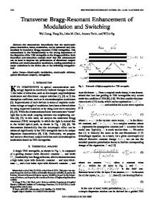
Figure 2. General Test Arrangement A low frequency swept-sine vibration component was superimposed onto a conventional pseudo-random vibration profile and a step-stressing procedure was applied to the vibration levels. At each vibration level, the temperature and humidity profile was cycled (Figure 3), to the extremes of their intended operating range and each unit was sequentially subjected to vibration in all three planes. The units were tested with their anti-vibration (AV) mounts off. The 7-step vibration profile is summarised in Table 1 and was defined so that level 3 roughly corresponded to the application specification limit.
Combined temperature humidity and vibration in standard chamber. Rapid thermal cycling using directed air. HALT tri-axial (6 degrees of freedom) vibration test.
5. COMBINED TEMPERATURE, HUMIDITY AND VIBRATION
120 Temp. °C / Humidity RH%
The first is more traditional but featured swept sine on random vibration with stepping of the vibration stress level. The other two regimes followed newer currently highly promoted techniques of very rapid thermal cycling and 6 degrees of freedom vibration stepping to failure, a techniques commonly called HALT.
Temperature/Humidity Profile
100 80 60 40 20 0 -20 0
60
120
180
240
-40 -60 Minutes
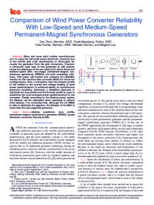
Three EMU units were simultaneously subjected to this test in 3 different vibration planes (Figure 1) using a conventional test chamber (Figure 2).
Figure 3. Temperature/Humidity Profile
Figure 1. Units on test (third unit hidden at back)
436
2003 PROCEEDINGS Annual RELIABILITY AND MAINTAINABILITY Symposium
Frequency Range Step
1 2 3 4 5 6 7 Sweep Rate Step Duration Orientation
Swept Sine 10 – 200 Hz
Random 10 – 2500 Hz
Input Level (gn)
Input Level (gn2 / Hz)
Cut off Frequency (Hz)* 1.0 10 1.59 10 2.0 11.2 2.52 12.5 3.18 13.5 4.0 15 5.0 16 1 sweep in 5 minutes (0.86 octaves/min
Input Level (gn RMS) 2.71 3.43 3.83 4.32 4.82 5.40 8.89
0.0030 0.0048 0.0060 0.0076 0.0095 0.0120 0.0300 *The sinusoidal displacement was limited to 8mm peak 2.5 hours/axis (7.5 hours / step)
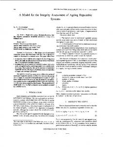
consistent with traditional methods and real life, i.e. each of these failures is relevant. Some photographs showing the damage induced by the testing process are given below (Figures 4, 5 and 6).
Detached legs
Three Planes simultaneous
Table 1: Summary of the vibration profile
Figure 4: Unit (1)
During testing, Unit (1) was powered and monitored only during the hot and heating sections; Unit (2) was powered and monitored all the time; Unit (3) was unpowered. At the end of each vibration step units were examined for signs of damage and fully functionally tested.
Blown capacitor
All Three units suffered mechanical failures at some stages of test, which were repaired before continuing. A summery of the test results is shown in table 2 Step 1 2 3
Input Level (gn) 1.0 1.59 2.0
Input Level (gn RMS) 2.71 3.43 3.83
4 5 6 7
2.52 3.18 4.0 5.0
4.32 4.82 5.4 8.89
Summary of results All pass All pass Unit 2 failed on completion of plane 3 during heating/hot section All pass Unit 1 failed following plane 1 Units 2,3 pass Units 2 and 3 failed in plane 3
Figure 5: Unit (2)
Loose Inductor
Table 2: Summary of test results At the end of the test the units were subject to a final strip inspection where the following faults were detected on each of the units (see Table 3). Unit 1
2
3
Fault Description No V90 rail. On the electrolytic capacitor C802, the lags had broken off the body (see photograph) Failed test 4a resistance to casting. Ceramic capacitor C36 had blown and short circuited to the casing (see photograph) No V90 rail. The medium sized electrolytic capacitor (C809) had become detached and the inductor core of L803 had loosened (see photograph). Also the legs on both large electrolytic capacitors (C802) has broken off.
Table 3: Details of failure modes Mechanical failures of electrolytic capacitor legs on the power board had previously been seen during traditional Design Validation (DV) and Production Validation (PV) testing with the AV mounts connected and from service returns. This shows that the failures produced by this testing technique are
Figure 6: Unit (3) The combination of using swept-sine on random vibration appears to generate relevant faults more readily than using either in isolation, based on the results from more standard tests carried out previously with these units. The total testing time to instigate these failures was about 50 hours, much less than conventional DV and PV testing periods, but still quite long. The main motivation for looking at rapid thermal cycling and tri-axis vibration is to try to reduce this testing time still further.
2003 PROCEEDINGS Annual RELIABILITY AND MAINTAINABILITY Symposium
437
6. RAPID THERMAL CYCLING Both ETPU and EMU units were subjected to rapid thermal cycling in the range 40-60 0C/min compared to conventional rates of 5-100C/min. The key idea is that the rapid change induces significant spatial temperature gradients between local parts of the unit due to different heating rates. These spatial gradients added to the inherent differences in thermal expansion coefficients of the materials lead to stress that causes weakness to be revealed as faults.
Results from Part 4 of Test procedure (Lid-off, 40 deg/min sweep, with d ll ) 2 - Outer Casing - Lower 5 - Lower PCB - Base Left 8 - Lower PCB - Top Right
1 - Outer Casing - Upper 4 - Upper PCB - Right 7 - Lower PCB - Top Left
3 - Upper PCB - Left 6 - Lower PCB - Base Right 9 - Chamber temperature setting
80 70 60 Th 50 er mo 40 co upl e 30 Te mp 20 era tur e 10 (D eg 0 ree 0 s C) -10
Units were tested with covers removed and placed directly in the air stream (see Figure 7) and it was recognised that calibration is necessary to determine actual temperature excursions.
1000
2000
3000
4000
6000
5000
7000
8000
9000
10000
-20 -30 -40 -50
Time (s)
Figure 9: EMU unit cycled between –40oC and +80oC at a rate of 35oC/min with 30 minutes dwells (allowing time for the unit temperature to equilibrate) ETPU Calibration results @ 35 deg/min Channel 1 back
Channel 2 front upper
Channel 3 under pcb
Channel 4 front lower
Oven Profile
120 110 100 90
Figure 7: EMU mounted for rapid thermal cycling.
Thermocouple Temperature (Degrees C)
80 70 60 50 40 30 20 10 0 -10 0
200
400
600
800
1000
1200
1400
1600
1800
-20 -30 -40 -50 -60 -70 -80
Results from Part 3 of Test procedure (Lid-off, 40 deg/min sweep, no dwells) 1 - Outer Casing - Upper
2 - Outer Casing - Lower
3 - Upper PCB - Left
4 - Upper PCB - Right
5 - Lower PCB - Base Left
6 - Lower PCB - Base Right
7 - Lower PCB - Top Left
8 - Lower PCB - Top Right
9 - Chamber temperature setting
80
The rm ocouple Te m pe ra ture (De gre e s C)
60
40
20
0 0
200
400
600
800
1000
1200
1400
1600
1800
-20
-40
Time (s)
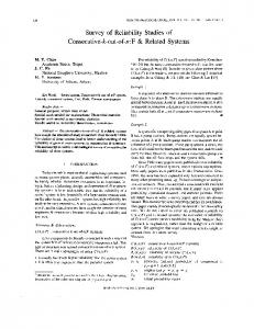
Figure 8: EMU unit cycled between –40oC and +80oC at a rate of 40oC/min Figure 8 shows the temperature read-out from 8 points within an EMU unit subjected to 40 0C/min cycling between - 40 0C and + 80 0C. This shows that even the exposed region experiences a reduced rate of change and a much lower temperature cycle range. To compensate, one either has to build in dwells at the extremes (see Figure 9) or overshoot the chamber temperature (see Figure 10). The latter was adopted but requires careful calibration if the unit’s temperature is not to significantly exceed its intended operating range.
438
Time (s)
Figure 10: ETPU cycled between –76oC and +122oC at a rate of 35oC/min. A variety of tests were carried out using rapid thermal cycling, with by and large disappointing results. It proved very difficult to initiate faults of any kind by rapid thermal cycling between the intended operating temperature extremes of the units. As an example, after 15 hours of the cycling profile depicted in Figure 10 an ETPU unit was still functioning perfectly. Extending the cycling rate to in excess of 50 0C/min, with 5 minutes dwells and continuing for a further 2 hours still initiated no faults. Only when the chamber temperature was uniformly stepped in + 5 0C intervals to a temperature of 1450C did the first failures become evident. The principal failure recorded was due to the pressure transducer, which had an operating maximum temperature of 1250C, so the failure was deemed not relevant. Close visual inspection of the unit did reveal several other less consequential faults, such as loose PCB mounting pillars and a lifted link wire. 7. TRI-AXIS VIBRATION A tri-axis vibration test chamber is capable of vibrating the unit under test in all possible directions simultaneously. Thus one potential advantage of the method is that it is quicker to carry out the tests, and one might also reasonably argue that
2003 PROCEEDINGS Annual RELIABILITY AND MAINTAINABILITY Symposium
vibration in all directions simultaneously is the most fieldrelevant case. It needs to be recognised, however, that the vibration profile is generated by a rapid impact process, so that the nature of the vibration spectrum will not necessarily correspond to that found using other methods of generation. The equipment used for this type of testing usually has rapid thermal cycling capability as well and the chamber and the methodology recommended by the manufacturers has become known by the acronym, HALT, (Highly Accelerated Life Testing). In all, seven distinct tests were carried out using a standard, commercially available, HALT chamber. Significant attention was given to the mounting of the units being tested so as to effectively couple the vibration, e.g. for the ETPUs the units were held down with crossbars placed across them; in turn, the units were placed on oak slats, which were directly placed on the test bench (see Figure 11).
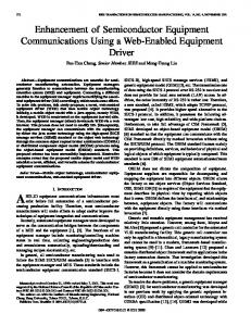
combined thermal cycling, humidity and vibration test discussed above, suggesting that similar faults are being induced at these high vibration levels but in a much shorter time period (less than 4 hours). As an example of an interesting (and relevant) fault not induced by the other techniques, in four out of five instances Tranzorbe (lightning strike protection) diodes on the ETPUs were found to have a single fractured lead (see Figure 12). It is worth noting that failures on these devices, by their very nature, are very hard to test for electrically but from experience large axial components are likely to be a first point of weakness.
Figure 12: Showing the broken Tranzorbe leads.
Figure 11:showing the mounting for the ETPU’s The vibration profile of the test chamber is roughly flat between about 750Hz and 2500Hz, falling off rapidly at lower and higher frequencies. As the energy is increased, so the shape of the spectrum stays roughly constant and only its absolute level changes. Thus only the parameter grms is required to specify the vibration. It was noticed that there was a considerable discrepancy between the grms value being displayed on the test chamber’s control panel, and the unfiltered signal derived directly from the accelerometers. This unfiltered signal was used in all cases to judge the vibration level at the unit itself. For a typical test, the temperature was fixed (EMU: -40°C, +20°C, +80°C; ETPU: -50°C, +20°C, +100°C) and the vibration level stepped, starting at 5grms and increasing by 5grms every 30 minutes up to a maximum level of 60grms. Such values are well in excess of the values quoted for the more conventional tests reported above, showing that one cannot make a direct comparison of the two, quite distinct, vibration spectra. In no instance was any fault induced below a level of 50grms, whilst all the units failed in some respect once the vibration was increased above this level. This was usually due to components becoming loose, principally capacitors and inductors. The peripheral damage to other capacitors and inductors still in place was very typical of that observed in the
There are several comments one can make about the tri-axis tests. Clearly the two unit types are similar in many respects. Both are extremely robust and have had all the generic faults designed out of them already. With different units that are still in the development cycle, one would expect to use much lower vibration levels to detect latent faults. There seems to be minimal benefit to conducting such stepvibration tests at extreme temperatures (as opposed to ambient temperature). One might attempt to argue that some of the eventual failures were more due to thermal over-stressing than to vibration, but this would be hard to justify. The actual magnitude of the critical vibration level appears to be very large, but this is more to do with an inappropriate attempt to compare with a conventional test chamber. The nature of the vibration profile in the present case is quite distinct. The nature of the faults found correlate well with existing faults known to occur for units of this type, but there is quite a narrow window between ‘nothing’ happening and significant damage being caused. It is also clear, however, that one can design tests that give concrete answers to specific questions in a very short time period. 8. OVERALL OBSERVATIONS The work described in this paper provides a valuable insight into a number of issues relavant to RET. First, it has been possible to design fast and efficient tests that induce relavant failures as judged by previous experience and filed data.
2003 PROCEEDINGS Annual RELIABILITY AND MAINTAINABILITY Symposium
439
Second, combining swept-sine with random vibration is evidently more effective than using either of them in isolation. Third, tri-axis vibration can lead to relevant failures being induced in a very short time, although it is not easy to get the overall vibration level set correctly. Fourth, rapid thermal cycling is not particularly effective as a RET technique for units of this type. ACKNOWLEDGEMENTS I would like to record my thanks to the following for their contributions to the testing programme: Phil Goymer, Matthew Davies, and Richard Cunnington. REFERENCES 1. "Straight talk about accelerated stress testing" by Hnatek ER and Kysel EL, Sound and Vibration, Vol. 32 pp. 24-28 (1998)
University entitled 'The organisation and statistical analysis of an electronic component field failure database' and is a British expert on IEC TC56: WG2. She is overall project manager of REMM. Dr Bob Newman Goodrich Engine Control Systems York Rd, Hall Green Birmingham, UK Phone: +44 121 627 6600 Fax: +44 121 607 3749 Email:
[email protected]
Bob Newman graduated with a 1st Class honours degree and has a doctorate on Dielectric Thin films (1971). He has held a number of positions in the Microelectronics Hybrid Circuits group at TRW having responsibility for electronic packaging for harsh environment and led an MOD funded programme into the use of surface mount technology in engine controls. He became Process Engineering Manager in 1984 and continued in similar positions until 1995 when he was appointed Technology Consultant Electronic Packaging reporting to the Chief Engineer Electronics TRW.
2. "Accelerated stress testing in a time-driven product of the development process" by Lu Y, Loh HT, brombacher AC and den Ouden E, International Journal of Product Economics, Vol. 67 pp. 17-26 (2000) BIOGRAPHIES Prof Michael Kearney (presenting author) School of Electronics and Physical Sciences University of Surrey, Guildford Surrey, UK Phone: +44 1483 689410 Fax: +44 1483 534139 Email:
[email protected] Michael Kearney is Professor of Electronics and Director of the Advanced Technology Institute at the University of Surrey. Between 1995 and 2002 he was Professor of Electronic Device Engineering at Loughborough University, serving as Head of Department between 1997 and 2000, and before that he worked for GEC-Marconi Ltd., managing the company’s Long Range Research Laboratory between 1994 and 1995. His research interests are diverse, and is the author of over 80 papers in fields related to electronic device technology. He is a Fellow of the Institution of Electrical Engineers and a Fellow of the Institute of Physics. Dr Jane Marshall (corresponding author) Goodrich Engine Control Systems York Rd, Hall Green Birmingham, UK Phone: +44 121 627 6600 Fax: +44 121 607 3749 Email:
[email protected]
Jane Marshall has been employed at TRW since 1991 as a reliability statistician. Before then she was a lecturer in statistics at Nottingham Trent University where she was involved in external reliability courses and consultancy. At TRW she has been involved in many aspects of reliability including; Prediction; FMECA; FTA; reliability testing and data analysis on aerospace and automotive products. She has a Ph.D. from Loughborough
440
2003 PROCEEDINGS Annual RELIABILITY AND MAINTAINABILITY Symposium