WSEAS TRANSACTIONS on CIRCUITS and SYSTEMS
Jatmiko W, Jovan F, Dhiemas R.Y.S, T. Fukuda, K. Sekiyama
ROBOTS IMPLEMENTATION FOR ODOR SOURCE LOCALIZATION USING PSO ALGORITHM T. Fukuda, K. Sekiyama Nagoya University Dept. of Micro-Nano Systems Engineering Chikusa-ku, Nagoya JAPAN
Jatmiko W, Jovan F, Dhiemas R.Y.S Alvissalim M. Sakti, Fanany M Ivan, Febrian A Universitas Indonesia Faculty of Computer Science Margonda, Depok INDONESIA
[email protected]
Abstract: Research topics in robotic application is quite varies but one of the most interesting topic is odor source localization. This research combine the robot ability to recognize odor and track the movement so that robot can find the source. Most of the research are done to improve the algorithm to localize the source by using simulation software. This paper tries to verify the robustness of one of the localization method known as Particle Swarm Optimization (PSO) in the real-world implementation. This paper will shows robot model that used in the experiment and also discuss the architecture to implement robot behavior. A group of mobile robots equipped with wireless communication device and odor sensors is employed. The experiment is conduct in area of 488cm x 488cm with dynamic odor source in one end. The experiment also used a set of camera to track robots position. The experiement result verifies that PSO is technically sound for real-world odor source localization. In this experiment, PSO can localized the source in 360 seconds or bellow. Key–Words: PSO, Al-Fath, Odor Source
1
Introduction
oxide sensors. Another experiment about single odor source localization using single robot also reported by [2]. In this research they define clearly the target and how they can determine the odor source. However, both research is still focusing in utilize and enhance odor sensor ability.
The amount of researchs in the field of robotics application for odor-sensing technology has grown substantially, such as research of [1] and [2]. The researchs is driven by the various attractive applications, including the research for toxic gas leak and fire origin at its initial. Both researchs required the ability for sensing and localize the gas source. Robotic research in odor field was opened from the research of odor-sensing technology in 1999 by J.W. Gardner and P. N. Bartlett [3, 4]. In year 2006, Wisnu J. et al, propose a method to enable odor sensor systems to recognize fragrance mixture [5] Their research presents the state-of-the-art in electronic noses. It can also be considered as a guide and a reference to develop odorsensing application such as in robotic research. Researchs carried out by Michael Wandel [1, 6], et al tried to demonstrate odor sensing system that able to detect volatile substances. The investigations showed that even weak odour could be sensed and the influence of the environment was rather negligible. They revealed that the performance of the mobile odor sensing system could be significantly enhanced by making mobile robot moved with not too low and constant speed. By moving in this manner, robot could add an extra airflow relative to the metal
ISSN: 1109-2734
Other researchs was performed by Adam T. Hayes et al [7, 8, 9] that used multiple robots to localize the odor source. They used distributed algorithm for solving the full odor localization task and shows that in the term of odor localization, group performance can exceed the perfomance of single robot. They have demonstrated that one subtask and plume traversal concept can be successfully used to locate odor source using real robots. Eventhough multiple robots were used, communication between robots was never happen. Robot information about odor concentration is kept for its self, rather than being distributed to the others. With the algorithm proposed by them, there is a chance that robots search in the same area repeatedly. To handle distribution of information problems, one of our previous research for odor localization uses the Particle Swarm Optimization (PSO) algorithm. The PSO algorithm has been proven successful in locating odor sources using 2D simulation soft-
115
Issue 4, Volume 10, April 2011
WSEAS TRANSACTIONS on CIRCUITS and SYSTEMS
Jatmiko W, Jovan F, Dhiemas R.Y.S, T. Fukuda, K. Sekiyama
determine robot position is describe in section 4, section 5 will describe the field and all the accessory used to construct simple dynamic environment for the experiments, the corresponding experimental results are then presented in section 6, followed by conclusions and suggestions for future work in section 7.
ware. The full report for this resarch and 2D simulation software can be found in [10]. Under PSO, every robot will be treat as particle and communication between these particles become the main key to locate the odor quickly. Several advances have been made in modifying Particle Swarm Optimization to make it more robust. One of the approach is by reinitializing the global best value whenever the robots are trapped in local maximum, named PSO Detect and Respond (DR) [11]. Another approach is to utilize wind to make the odor source localization faster [12]. Although the use of simulators to measure performance of Particle Swarm Optimization is quite useful, results from the simulation software might not represent the actual performance. Therefore, to measure the actual performance of Particle Swarm Optimization algorithm for locating an odor source, it is necessary to implement it on a real hardware. This research aims to verify the robustness of PSO-based odor source localization on a real world. A group of robots equipped with wireless communication device and odor sensors is employed to participate in this research. It’s in the nature of Particle Swarm Optimization algorithm that this algorithm requires information about the position of each robot. In simulation software, the position of each robot can be easily determined because each robot position is also needed for the calculation of simulation, hence this data is already stored in a variable. However, in real world it is quite different and difficult. The location where the localization is conducted will also impact on the device that can be used to measure robot position hence this also interfere on the position error which inherrited from the device that we use. For outdoor localization, a global positioning (GPS) device is usually used. GPS can provide reliable location information anywhere on Earth when there is an unobstructed line of sight to four or more GPS satellites. For indoor localization, GPS device does not perform well due to the blockage of buildings. With obstacles between GPS satellites and its object, the accuracy will be low hence this information can not be used. This research is designed for determine PSO robustness in indoor localization. It is then decided that to provide the position of each robots, a group of webcameras is utilized in this research. Images that provided by webcameras then being manipulate using image processing techniques, this manipulation will gives the data that needed by PSO. The rest of this paper is structured as follows: in section 2 the PSO algorithm is described, robot design and sensors are described in section 3, systems architecture that includes camera settings and process to ISSN: 1109-2734
2
Particle Swarm Framework
Optimization
The particle swarm concept was originated as a simulation of simplified social system. The original intention was to graphically simulate the choreography of birds or fish school. However, it was found that particle swarm model can be used as an optimizer by Dr. Eberhart and Dr. Kennedy in 1995[13, 14]. With their improvement, Particle Swarm Optimization (PSO) is often used to find global maximum or global minimum of a function. Although it is generally used in static problems, PSO has also proved useful in dynamic problems where the environment dynamically changes [15]. In that research, Dr. Eberhart et al proposed a PSO with a few modifications to handle dynamic environments. They introduced two environment detection methods by using global best value as the parameter. ChangegBest-value method and Fixed-gBest-value method can succesfully detect the various dynamic changes. These features is embellished by the ability to respond to a wide variety of changes. They called these methods as detect and response. Particle Swarm Optimization as one branch of evolutionary algorithm (EA) has proven successful in a number of static applications as well as dynamic and stochastic optimization problems [16, 17]. They are particularly successful in problems involving measurements that account for the uncertainty that present in the real world. Every individual in PSO is assumed as a particle and actively contribute to solve the problem. Each particle is trying to optimize its fitness function by exploring the search space using its own information as well as information from other individuals. Value that aquired from fitness function will determine the fitness of the solution that particle have, the greater the fitness value means the closer that solution to the optimum solution. Each individual must keep track of its best position which is the position with the highest fitness function value perceived. This position is called the personal best or local best value. Beside local best, PSO also have something called global best position. The global best position is the highest the position with the highest value among all the local bests. Each individual must also keep track of its current velocity vector and update it periodically. 116
Issue 4, Volume 10, April 2011
WSEAS TRANSACTIONS on CIRCUITS and SYSTEMS
Jatmiko W, Jovan F, Dhiemas R.Y.S, T. Fukuda, K. Sekiyama
In odor source localization context, each robot acts as a particle exploring the search space. The search space is the physical space which the robot can occupy. The fitness function uses the concentration value of odor that detected by robot sensors from the environment around it. All the robots try to optimize their position to get nearer to the position that has the highest value of odor concentration. Robots have been given predetermine threshold value so that whenever a robot detected odor concentration that higher than the threshold then it’s safe to claim that the source has been found and search can be terminated. Suppose the position and velocity of the i-th robot at iteration t (where t = 1, 2, ...) are represented by Xi (t) and Vi (t). Let pi and pg defined as best local and the best global position that evaluated by the robot. The position and the velocity of each robot are updated at each time step to guide the robot exploring the search space and to improve the fitness function. A fitness function is needed to evaluate the fitness of every position that have been found.
constriction factor is used to limit the velocity. The coefficient c1 and c2 are learning parameters which represents the tendency of individual to follow local best and global best. When c1 is greater than c2 then the particle tends to move towards its local best position. Otherwise, when c2 is greater than c1 the particle tends to move towards global best position. For solving problems with single solution, it is best to have c2 that greater than c1 [18]. PSO algorithm is a convergent algorithm, which means that all particles at a particular iteration will eventually wander around global best position. If this happens, then the movement of those particles would not be too significant hence make PSO computation becomes ineffective. At this point decision must made to decide whether to continue the search will or not. In other words, PSO must determines whether the convergence behavior occurs because the particle have found a solution, so that the search can be considered successful or not. There are several conditions that can be used as parameters to make the PSO stops [19]. This research chooses two of them to be used as parameters, the parameters are describe as follows:
individual
Vin+1
=χ
(Vin
z }| { + c1 .Rand().(pni − xni ) +
(1)
1. Iteration steps already exceeded the time limit. Time is always be an important thing to take into account. If the time limit is too tight, the search will stop before any solution is found. If the time limit is too loose, this will make unnecessary computational cost due to the PSO computation that being done by robots after PSO reach convergence state.
social
}| { z c2 .rand().(png − xni )) Xin+1 =Xin + Vin+1
(2)
The closer position to solution, the greater the fitness value will be. By using fitness function, every position which has been explored can be compared one to others in order to determine which position is closer the the solution (in this case, the odor source). When a robot discovers a better position with a higher odor sensor reading, its local best is updated. The difference between pi and the current position Xi (t) is stochastically combined with the current velocity Vi (t). The update of velocity causes change in robots trajectory and moves robots to new position. The stochastically weighted difference between the populations best position pg and individual current position xi is also added to the velocity to adjust the velocity vector. The addition of the two vectors cause the robot to search between its local best position and the global best position. Using this mechanism will eventually makes the robots converge to a single position until another global best is found. The velocity and position vector is calculated using Equation 1 and 2. Functions Rand() and rand() are random generator functions that will return value between (0, 1) [12]. The χ coefficient is constriction factor, which have the value that less than 1. The ISSN: 1109-2734
2. An acceptable solution has been found. The search will be stopped when theres any robot had a fitness value that exceeds the given threshold.
3 3.1
Robot Design Robot Platform
To verify the robustness of PSO algorithm, robot that will implement PSO must be build. The robots used in this research are built based on the Traxter II platform. This robot was first developed to participate in robotic competition which task is to put out fire sources inside a house miniature. The name of the robot is Al-Fath, it cames from Arab language that means victory. The first version of Al-Fath is equipped with various sensors such as compass, sonar ranging sensor, and incremental encoder. For this research Al-Fath must be moddified. In order to allow communication between robots, we add a wirelesscommunication device. This robot is also need to detect odor that planned to be search, hence we add pair 117
Issue 4, Volume 10, April 2011
WSEAS TRANSACTIONS on CIRCUITS and SYSTEMS
Jatmiko W, Jovan F, Dhiemas R.Y.S, T. Fukuda, K. Sekiyama
(a) Front view
(b) Side view
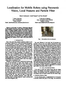
Figure 1: Al-Fath Model (in centimeters)
Table 1: Hardware specification Hardware Name Used As Atmel AT-MEGA 2560 Main Processor Atmel AT-MEGA 8 Slave Processor TGS2600 Odor Sensor CMPS03 Digital Compass YS1020U Wireless UART SRF08 Ultrasonic Ranger
Number 1 2 2 1 1 2
of odor-sensors to the platform. Overall, Al-fath with every sensors attached has 23.5 cm in length, 20.3 cm in width and 27.8 in height. The design of robot used in the research is shown in Fig. 1. As seen in Table 1, Al-Fath is consisted of odor sensor, compass, wireless UART and sonar range sensor as its media to interact with the environment, while AT-MEGA 2560 and AT-MEGA 8 as its brain. Atmels AT-MEGA 2560 is an 8-bit microcontroller operating at 11.059200 MHz. It is used as main controller which handles most operations in the robot. Main controller roles are described as follows: • As a master. • Compass value, encoder value and SRF08 value reader. • Navigation control. • Reactor of sensor microswitch. • Controller of data deliveries to LCD. • Controller of data deliveries to Wireless UART. A pair of Atmels AT-MEGA 8 is used for left and right motor speed control and odometry. The microcontrollers communicate using built-in UART communication module. List of the component that being
ISSN: 1109-2734
Figure 2: Al-Fath Brain Structure handler by AT-MEGA 2560 and AT-MEGA 8 can be seen in Fig. 2.
3.2
Sensors
Figaro metal-oxide sensors were used to measure relative odor concentrations. These sensors contain a heating element to maintain a constant operating temperature of approximately 300o C [4]. The electrical resistance of the semiconductor affected by redox reactions of the sensed odor with the sensor surface is used to measured odor quantity. Differently doped materials provide slightly varying sensor characteristics, although metal-oxide sensors are not highly selective in general. This sensor were chosen for our experiments because of their high sensitivity, sufficient to detect odor concentration from distance of several meters. Due to the physics of the measuring principle the time constants of the response and recovery of the sensors are quite long (in the order of a few seconds for response, and a few tens of seconds for recovery). Thus considerable temporal integration of successive readings is always performed implicitly by the sensors themselves. Graphic explaining the odor sensor characteristic can be seen in Fig. 3. To avoid collision among robots and between robot and the walls, Al-Fath is equipped with ultra-
118
Issue 4, Volume 10, April 2011
WSEAS TRANSACTIONS on CIRCUITS and SYSTEMS
Jatmiko W, Jovan F, Dhiemas R.Y.S, T. Fukuda, K. Sekiyama
Figure 3: Odor sensor characteristic.
Figure 5: Software architecture.
4
The software running the Particle Swarm Optimization Algorithm consists of three key modules. These three modules are Behaviour Module, Camera Module, and Communication Module as illustrated in Fig. 5. As can be seen in the architecture, main computation for PSO is performed at the master computer (PC). All robots only perform computation when they recieve direction from PC, hence this architecture treats robots as slave. As a slave, the robot has responsibility to manage all components added in the body, as state in Fig. 2. Robots must always try to follow and provide as asked by the master PC. This architecture was chosen to provide faster development cycle since reprogramming the robots microcontroller is time consuming.
Figure 4: Al-Fath Physical View
sonic rangers. We select ultrasonic rangers rather than infrared sensor because the ultrasonic wave produced by ultrasonic rangers are conical. This makes the region to detect objects in front of Al-Fath greater by only using a few sensors. Digital compass is used to determine the direction of the robot by reading the magnetic field in spesific points. The maximum resolution of compass is 0.1 degree, while it’s accuracy is around 3-4 degrees. Error that made by digital compass is influenced by the presence of surrounding metals. Metals can give a great influenced in compass reading, this sensors is not fitted to be used in the area that have a great number of metal.
4.1
Behaviour Module
The Behaviour Module is a module that manage the behaviours of all robots. This module consists of data center, robot’s thread, and supervisor. Each robot’s thread will compute new velocity vector of associate robot and will update robots local best position. The pseudocode of the algorithm is shown in below.
Communication between robots uses a wireless UART module. All the wireless UART device is set to use the same frequency, therefore a protocol must be designed so that no communication crash occur. Communication protocol used in this research is build from the scracth and explained in Section 4.3. The standard model of Al-Fath is shown in Fig. 4. ISSN: 1109-2734
Architecture
repeat 119
Issue 4, Volume 10, April 2011
WSEAS TRANSACTIONS on CIRCUITS and SYSTEMS
Jatmiko W, Jovan F, Dhiemas R.Y.S, T. Fukuda, K. Sekiyama
for each particle i // set local best if f(xi ) is better than f(lbest) then lbest = xi end if // set global best if f(xi ) is better than f(gbest) then gbest = xi end if end for for each particle i update velocity and position using Equation 1 end for until stopping condition is true
Figure 6: Twelve camera design.
In addition, robot’s thread also collects every information related to the associate robot. Collected informations are organized in the data center based on time arrival and robot’s thread id. Beside local best, PSO also need global best value. Global best value is computed in the data center based on the last local best information. The best of all local best in the data center will be nominated as global best. This global best value is treated as shared data and can be accessed by all robot’s thread. Supervisor is prepared to handle changing in environment. Yet in the term of this research, the implementation of this module is being suspended. The process run by each thread and the breakdown of the module is shown Fig. 5.
4.2
Figure 7: Al-Fath robot with color identifier mounted in top. covers a region of 216 x 167 cm wide. There are some regions where camera view might intersect with each other. This is done to support smooth transition between regions and to confirm that robots do not disappear from the system while in transite between regions. To simplify the robot position tracking process, color signatures are mounted on top of the robots. The color signature is a multi-colored circle as pictured in Fig. 7. This type of color signature gives an advantage in extensibility. Whenever the number of robots increases, one can easily add the number of color layers to distinguish them. The image processing technique employed is Color Filtering and Blobs Filtering. Color Filtering Technique is used to filter a specific color from an image, so that only part of the image with a specific color remains. By using basic colors(Red, Green, Blue) as color signatures, HSL (Hue, Saturation and Luminance) method become available to be used to filter the colors. In addition, HSL method can tolerate the change of light intensity in an environment. Configuration the color filters used can be seen in Table 2.
Camera Module
In order to implement PSO, the program needs to know the position of each robot. Camera module is developed to serve that need. The module is implemented as a webservice running on several computers managing 12 web cameras. This method can be considered as GPS adhock. In real application, this module can be replaced by a Global Positioning Device (GPS) but remember to check the accuration for particular search area. Twelve cameras (Fig. 6) that used in this research are standard Webcam. The specification of these camera are having image resolution about 320 x 240 pixels and can capture about 30 frame per seconds. The cameras are placed on the ceiling of the room facing towards the ground. Every camera are configured to ISSN: 1109-2734
120
Issue 4, Volume 10, April 2011
WSEAS TRANSACTIONS on CIRCUITS and SYSTEMS
Color Red Green Blue
Jatmiko W, Jovan F, Dhiemas R.Y.S, T. Fukuda, K. Sekiyama
Table 2: HSL Configuration Hue Saturation Luminance 347 - 11 0.45 - 1.00 0.30 - 0.90 66 - 172 0.20 - 1.00 0.20 - 1.00 202 - 300 0.23 - 1.00 0.10 - 0.64
Figure 9: Communication flow.
Where Index Xi and Index Yi are indexs for Camera-i, δx is the deviation of the camera position on the X-axis (horizontal), and δy is the deviation of the camera position on the Y-ordinat (vertical).
Figure 8: Camera configuration uses many cameras. Results from the filtering process is then processed with Blobs Filtering. This technique is used to detect the object (blobs) on image input by using color value of the pixel in an area. The color signature circles will be identified as blobs in this process. Once the location of the blob is found, the location of the robot can be represented by it. To get an absolute position of the robot (xabs , yabs ), a relative position from center point of the right blob can be used (xcenter , ycenter ). For single camera (xabs , yabs ) can be gotten as follows: center abs } {xyabs } = S × {xycenter
4.3
All communication is managed by a program in PC named the Communication Module. Since the entire wireless UART modules operate on the same frequency, communication must be managed so that no conflicts occur. The communication module is implemented as a webserver which serves a request from clients. Other programs can communicate with the communication module to obtain sensor data from each robots and give direction to robots. It can also be accessed from a regular webbrowser. Requests from the behavior module to communication module have to be queued in the communication module, while requests for information from the behavior module toward the camera module can be processed instantly. This is due to the process time to obtain data from each sensor varies. The information’s flow from behavior module to Al-Fath can be seen in Fig. 9. Periodically every robot’s thread in the behavior module will request updated information of sensor from communication modules. At the time of PSO iterations performed, thread PSO on the behavior module will send commands to the communication protocol module. Each request from the behavior module will be queued on the communication protocol mod-
(3)
Where S is described as follows:
S=
f ieldlength f ramewidth
(4)
The Eq. 3 needs to be modified to apply in the case of many cameras. Suppose the camera is placed as in Fig. 8, the robot position (x, y) can be determined as follows: (length−of f setX)×IndexX
abs {xy } = {xyabs } × {(width−of f setY )×IndexYi i } + {δδxy }
(5) ISSN: 1109-2734
Communication Module
121
Issue 4, Volume 10, April 2011
WSEAS TRANSACTIONS on CIRCUITS and SYSTEMS
Jatmiko W, Jovan F, Dhiemas R.Y.S, T. Fukuda, K. Sekiyama
ule. Requests/commands contained in the queue will be sent one by one to Al-Fath. Requests/commands will not be sent to Al-Fath from the communication protocol module if the feedback from the intended AlFath has not been received. However the time limit is given to the packet before the next command is sent. Commands which do not get feedback until the time limit is considered as a packet drop. Figure 10: The odor-source generation mechanism.
5
Field Setting
• Scenario I. (Fig. 11a) All the three robots were positioned opposing the source and the direction of exhaust was static throughout the experiment. Condition in the first scenario represented environment with stable wind where robots had moved against wind direction.
The field used for the experiment is a 488x488 cm2 area with 50 cm high walls on the perimeter. The field has a quite large dimension to distribute the odor concentration in various positions. The field is placed in the unventilated indoor environments which is dominated by turbulence rather than diffusion [20]. Thus an ideal distribution of the odor with a single peak at location of the source would not never happen. Rather than it, a patchy distribution of temporally fluctuating eddies results is possible to happen [21, 22]. In this respect, the robot itself can be seen as part of the environment due to its influence on physical parameters such as local air currents. In one of the four walls, an odor source is placed. In this experiment, ethanol is used as the source of odor. Half a liter of 95% liquid ethanol is stored in the ethanol storage. Ethanol evaporates quite easily on room temperature. Thus, the ethanol storage also contains ethanol in gas form. In an unventilated room, it is imposibble to model the airflow dynamics accurately. One way to overcome this problem is to add a sufficiently strong artificial air current that superimposes the complicated turbulent gas distribution with a more simple plume-like structure [7]. An air compressor becomes an option to make strong artificial air current so that the odor can burst out and be distributed to the entire field. The direction of the source can be controlled along the horizontal axis. The odor generation mechanism is displayed in Fig. 10.
6
• Scenario II. (Fig. 11b) Robots started the search at the same position as the first scenario. However, the direction of the exhaust was changing throughout the experiment (Fig. 11b). This condition represented dynamic environment with unstable wind. • Scenario III. (Fig. 11c) Robots were initially positioned and faced parallel to the direction of exhaust and the exhaust direction was static throughout the experiment. This condition represented environment with stable wind where robots had not moved against wind direction. It was used to be compared with first scenario in term of time. Fig. 13 and Fig. 14 shows the result of an experiment with second scenario and third scenario. As shown in those figure, the needed time to accomplish the given task is same eventhough the environment is different. In third scenario, the time is used to compensate the initial position of robots located outside the flow of source, while second scenario uses the time to compensate the unstable wind. The results of the experiments are shown in Table 3. In four out of six experiments, the outcome were successful. In the first scenario, robots were able to locate the odor source under six minutes regardless where the source was placed eventhough the needed time is different. In the second and third scenarios, robots were not able to locate the odor source under six minutes where the source is placed near corner of the wall (Fourth and Sixth experiments in Table
Experiment Result
Six experiments were conducted, each with a timeout of 360 seconds. There were three scenarios involved. Each scenario was run twice with different position of the source (in the middle and corner of the wall). Three robots were involved in each scenario. Three scenario prepared is described as below: ISSN: 1109-2734
122
Issue 4, Volume 10, April 2011
WSEAS TRANSACTIONS on CIRCUITS and SYSTEMS
(a) Scenario I
Jatmiko W, Jovan F, Dhiemas R.Y.S, T. Fukuda, K. Sekiyama
(b) Scenario II
(c) Scenario III
Figure 11: Three scenarios for odor source experiments.
(a)
(b)
Figure 12: Successful trial with three robots on first scenario.
(a)
(b)
Figure 13: Successful trial with three robots on second scenario. 3). The two failures were due to the position of the source. The robots eventually wander around a single point near the source although it is not the goal. The global best position is not updated until the search
ISSN: 1109-2734
time exceeds.
123
Issue 4, Volume 10, April 2011
WSEAS TRANSACTIONS on CIRCUITS and SYSTEMS
Jatmiko W, Jovan F, Dhiemas R.Y.S, T. Fukuda, K. Sekiyama
(a)
(b)
Figure 14: Successful trial with three robots on third scenario.
No 1 2 3 4 5 6
7
centered. This surely boost up the chance for data collision when the behavior module send commands simultaneously. To handle this problem, distributed communication module with multi transmitters can be considered as one of the option. Distributed communication module can avoid the frequency’s collision because of multi frequencies that are used.
Table 3: Experiment Outcome Scenario used Search Time Success/Fail Scenario I 219 Success Scenario I 315 Success Scenario II 241 Success Scenario II 360 Fail Scenario III 234 Success Scenario III 360 Fail
Acknowledgements: This work was supported in part by the Incentive Research Program No. 326F / DRPM-UI / A / N1.4 / 2009 by the Ministry of Research and Technology Republic of Indonesia and in part by Grant of Joint Research for Foreign Affairs and International Publication No. 2186 / H2.R12.3 / PPM.00 Penelitian / 2010 by the Ministry of Education.
Conclusions and Furture Works
This paper has show that Particle Swarm Optimization algorithm suitable for odor source localization problems. PSO has been proven quite successful on the real dynamic environment. Using three robots to locate the source in the medium area is can be done within 360 seconds. However there’s a problems when the source is placed in the corner of search area, this is due to the nature of collision avoidance algorithm implement in robots. It’s also shown that by using standard PSO, there is a possibility for robots to be trapped in a local best position caused by its convergence characteristic. Furthermore, problems with localizing odor is not limited to a single odor source hence failure in localized can not be avoided. Therefore, a more modification to PSO, such as PSO Detect and Respond and Charged PSO, is needed to avoid the trap and also handle multiple sources problems. We try to analyze the feasibility to implement more advanced PSO in future work. The same problems goes to the size of search area, the bigger the area the harder it takes to localized the odor. In this experiment, the communication module is
ISSN: 1109-2734
References: [1] M. Wandel, A. Lilienthal, T. Duckett, U. Weimar, and A. Zell. Gas distribution in unventilated indoor environments inspected by a mobile robot. In Proceedings of the IEEE International Conference on Advanced Robotics (ICAR03), 2003. [2] Wisnu Jatmiko, T. Fukuda, T. Matsuno, F. Arai and B. Kusumoputro, Robotic Applications for Odor-Sensing Technology: Progress and Challenge, WSEAS Transaction on System, Issue 7, Volume 4, pp. 1134-1141, July 2005. [3] G T. C. Pearce, S. S. Schiffman, H. T. Nagle, and J. W. Gardner, Handbook of Machine Olfaction: Electronic Nose Technology. Weinheim, Germany: Wiley VCH, 2002.
124
Issue 4, Volume 10, April 2011
WSEAS TRANSACTIONS on CIRCUITS and SYSTEMS
Jatmiko W, Jovan F, Dhiemas R.Y.S, T. Fukuda, K. Sekiyama
[4] J.W. Gardner and P. N. Bartlett, Electronic Nose: Principles and Applications. New York: Oxford Univ. Press, 1999. [14]
[5] Wisnu Jatmiko, T. Fukuda, F. Arai, and B. Kusumoputro, Artificial Odor Discrimination System Using Multiple Quartz Resonator Sensor and Various Neural Networks for Recognizing Fragrance Mixtures, IEEE Sensors Journal, vol. 6. no. 1, pp. 223233, Feb. 2006.
[15]
[6] M. Wandel, A.Hayes. Sensing odour sources in indoor environments without a constant airflow by a mobile robot. In Proceedings of the IEEE International Conference on Advanced Robotics (ICAR01), 2001.
[16]
[7] A. Hayes, A. Martinoli, and R.M.Goodman. Distributed Odor Source Localization. IEEE Sensors Journal, Special Issue on Electronic Nose Technologies, 2(3):260273, 2002. June.
[17]
[8] A. Hayes, A. Martinoli, and R.M.Goodman. Swarm Robotic Odor Localization: Off-Line Optimization and Validation with Real Robots. Robotica, vol. 21, num. 4, 2003, p. 427-441.
[18]
[9] A. Hayes, A. Martinoli, and R.M.Goodman. Odor Source Localization with Mobile Robots. Bulletin of the Swiss Society for Automatic Control, num. 46, 2007, p. 11-14. [10] W. Jatmiko, K. Sekiyama and T. Fukuda, A PSObased Mobile Sensor Network for Odor Source Localization in Dynamic Environment: Theory, Simulation and Measurement, Proc. of the IEEE CEC-WCCI ”Congress Evolutionary Computation - Word Congress on Computational Intelligence” pp. 3781-3788, 2006.
[19] [20]
[21]
[11] Wisnu Jatmiko, K. Sekiyama and T. Fukuda, Modified Particle Swarm Robotic for Odor Source Localization in Dynamic Environment. The International Journal of Intelligent Control and Systems: Special Issue on Swarm Robotic, Vol. 11, No 3, pp.176-184, September 2006.
[22] [23]
[12] Wisnu Jatmiko, Petrus Mursanto, Benyamin Kusumoputro, K. Sekiyama and T. Fukuda, Modified PSO Algorithm Based on Flow of Wind for Odor Source Localization Problems in Dynamic Environments. WSEAS Transaction on System, Issue 3, Volume 7, pp. 106-113, March 2008.
of the Sixth International Symposium on Micromachine and Human Science, Nagoya, Japan. pp. 39-43, 1995. Kennedy, J. and Eberhart, R. C. Particle swarm optimization. Proceedings of IEEE International Conference on Neural Networks, Piscataway, NJ. pp. 1942-1948, 1995. X. Hu, R. Eberhart. Adaptive Particle Swarm Optimization: Detection and Response to Dynamic System. Proceedings of the IEEE Congress on Evolutionary Computation (CEC), pp. 1666-1670, 2002. Li, X., Dam, K.H. Comparing Particle Swarms for Tracking Extrema in Dynamic Environments. Congress on Evolutionary Computation 3, 17721779, 2003. A. Carlisle, G. Dozier. Adapting Particle Swarm Optimization to Dynamic Environment. Proceeding of the International Conference on Artificial Intelligence, pp. 429 - 434, 2000. Wisnu Jatmiko, K. Sekiyama and T. Fukuda, A PSO-based Mobile Robot for Odor Source Localization in Extreme Dynamic AdvectionDiffusion Environment with Obstacle: Theory, Simulation and Measurement. IEEE Computational Intelligence Magazine: Special Issue on Biometric. Vol. 2, Issue 2, pp. 37-51, May 2007. Engelbrecht, Andries P. Fundamentals of Computational Swarm Intelligence. Wiley, 2005. T. Nakamoto, H. Ishida, and T. Moriizumi. A Sensing System for Odor Plumes. Analytical Chem. News and Features, 1:531537, August 1999. A. J. Lilienthal and T. Duckett. Experimental Analysis of Smelling Braitenberg Vehicles. submitted to ICAR 2003, 2003. R. A. Russell. Odour Sensing for Mobile Robots. World Scientific, 1999. M. R. Wandel, U. Weimar, A. J. Lilienthal, and A. Zell. Leakage Localisation with a Mobile Robot Carrying Chemical Sensors. In International IEEE Conference on Electronics, Circuits, and Systems (ICECS), pages 1247 1250, Malta, September, 25 2001. GDI.
[13] Eberhart, R. C. and Kennedy, J. A new optimizer using particle swarm theory. Proceedings ISSN: 1109-2734
125
Issue 4, Volume 10, April 2011