Seismic Performance Evaluation of TimberâFramed ...
Recommend Documents
Oct 7, 2015 - the IRC manual follows the 1988 FEMA-154 screening guide- lines (ATC .... CP based on FEMA 356 (2000) and FEMA P-58-1 (2012). The.
Mar 23, 2017 - when one is interested in asymmetric RCTF buildings whose past ..... accounting for the axialâbending interaction behavior of the wall mem-.
The Fitzgerald Avenue Bridge over the Avon River in Christchurch, New Zealand, will be used as a case study. It is a small-span twin-bridge that has been.
... a lot of R/C buildings were damaged and collapsed in Padang, the capital city of ..... The Eqs. (10) and (11) give the yield strength iVy and drift iįy, respectively.
major earthquake motions in the performance-based building code of Japan ... and 2) evaluation of site response from geotechnical data of surface soil layers.
Mar 23, 2017 - elements are designed based on building code requirements and implemented with adequate shear reinforce- ments, they .... Apart from lacking the reliable R-factor, two restricted issues pre- vent the ..... Hollywood. 6.7 25.7.
into account by modifying the moment-curvature relationships. Modified target post-yield stiffness of each structural member ensures the bond-slip relationships ...
Connections. Ki-Hoon Moon ^ and Sang-Whan Han^. ""Ph.D Candidate, Department of Architectural Engineering, Hanyang University, Seoul 133-79, Korea.
Oct 22, 2015 - Junwon Seo 1, Jong Wan Hu 2,* and Burte Davaajamts 1. 1 Department of Civil and Environmental Engineering, South Dakota State University ...
A two-dimensional section of a concrete gravity dam is evaluated using various ...
method for the seismic design of concrete gravity dams in Japan has been ...
May 6, 2002 - Low and medium rise non-seismic RC frame buildings designed only .... Concrete slabs, with a thickness of 100 mm, are provided at floor levels. ..... IM and of IMs at different levels of EDPs are also plotted beside and above ...
California at geographical coordinates 34.228 and 118.434. .... Hemet Fire Station. D .... Bazzurro, P. and Cornell, C.A. (1994), âSeismic hazard analysis of.
2004, Vargas & Bruneau 2007, Karavasilis & Seo 2011) and can be used for non-structural seismic ...... NASA Contractor Report No. 4444.: NASA. Erberik, M. A. ...
Oct 7, 2015 - components that are sensitive to the building alignments (e.g., elevator rails, curtain walls .... ties are evaluated using the IDA results. ⢠Step 4: ...
yapının asıl dinamik karakterlerine göre güncellenmistir. Güncellemeden ..... were extracted from AVT by using Frequency Domain Decomposition (FDD). A 3-D.
dential Code (IRC) (ICC 2000) and its prede- cessors allowing ... (Pardoen et al 2000; Uang 2001) despite the. IRC allowing shear resistance from walls not ..... 471. 1420. 389. 463 cycles to Pmax e. 18. 37. 19. 34. 21. 15. 29. Umax (mm). 2.4.
advisors, Professor Yozo Fujino and Associate Professor Masato Abe, provided a wealth of ideas and encouragement ..... Bridge (after Yamanouchi, 1998) A-12.
2 . Reinforcing bars used in the prototype building were D10. (10 mm diameter) and D19 (19 mm diameter) with yield strengths (fy) of 294.2 MPa (3,000 kgf/cm. 2. ) ...
Mar 4, 2014 - R 45. I 45. R 60 iso. Fixed raft. Foundation system with slope. Fixed. M1g. M 0.5 g. M 0.25 g. Mo m en t (m·t). (c) Base column bending moment.
AbstractâThis study was conducted to evaluate the seismic performance of weir structures using two different approaches: i) design response spectrum with ...
Among other things, the PBEE methodology can be used to estimate the mean .... building components that contribute the most to repair cost are structural ...
Analysis results are utilized to characterize the site hazard, specify target ... The selected site is the LA Bulk Mail facility in Bell, CA (coordinates 33.996° Lat.
Aug 22, 2014 - Academic Editor: Jung-Ryul Lee .... dampers is named the penta-slim-damper (PSD). Also ... test setups of SSD, TSD, and PSD, respectively.
The selected site is the LA Bulk Mail facility in Bell, CA (coordinates 33.996° Lat. -118.162°. Long,), located south of downtown Los Angeles. One would expect ...
Seismic Performance Evaluation of TimberâFramed ...
e-mail: [email protected]. N. Ruggieri. DIMES ... the experimental campaign results to the seismic behaviour deduced from historic photos and ... The use of the DIANA F.E. software distinguished the work of Ramos and. Lourenço [3].
Chapter 8
Seismic Performance Evaluation of Timber—Framed Masonry Walls Experimental Tests and Numerical Modelling Stefano Galassi, Nicola Ruggieri and Giacomo Tempesta
Abstract The Borbone constructive system used in Calabria at the end of the 1700s consisted of a particular composite structure realized by means of a timber frame suitably embedded inside masonry walls. This system used with similar purposes, although in different ways, in other places in the world (especially in seismic regions), can represent, with good reason, the synthesis of scientific knowledge in eighteenth century seismic engineering. The aim of the paper is to investigate and evaluate the seismic performance of the structure described above through a comparison between experimental tests, carried out by means of cyclic tests on 1:1 scale models, and the results obtained by the numerical modeling of the mechanical system that is capable of interpreting the actual contribution of the wooden structure, as well as that of the masonry, to the overall stiffness of the wall. In the numerical procedure, the masonry infill is modeled by rigid blocks connected by unilateral elastic contact constraints. A convenient way to define the contact device which links the blocks, through which a mortar joint or dry joint could be simulated, is to consider a set of elastic links, orthogonal to the contact surface between two adjacent blocks, and an additional link, parallel to the interface through which the shear forces can be transmitted. Reasonable hypotheses can be assumed for the link parallel to the contact surface in order to calibrate both the shear behaviour and the influence of the friction between the blocks. Furthermore the timber frame is modeled by using finite elements with elastic and bilateral
behaviour. Unilateral contact constraints are again used in the contact interfaces between elements in wood and masonry blocks which take into account the actual contribution of friction. The mechanical parameters used in the numerical model were deduced from the experimental laboratory tests. Keywords Seismic behaviour · Masonry reinforced · Timber frames · No tension behaviour
Introduction The Borbone constructive system, constituted by masonry reinforced with timber frames, represents the application of the most ancient of European anti-seismic codes. The Mileto Bishop’s building in Calabria, constructed immediately after the catastrophic earthquake of 1783, is characterized by a load bearing system executed exactly according to the Borbone rules. Therefore, after a detailed structural and geometric survey, including the material features, on the Mileto construction, the latter, in particular a wall modulus, had been reproduced in full scale and subjected to a cycling test in the CNR Ivalsa laboratory in Trento. The tested specimen was constituted by timber framing devoid of Saint Andrew crosses and stiffened, to the in plane seismic action, by means of the masonry infill. The wooden skeleton was characterized by half lap joints in which the stiffness was improved by the presence of pyramidal nails. Data to be used in the numerical model proposed were obtained by comparing the experimental campaign results to the seismic behaviour deduced from historic photos and documents that depict seismic failures after the 1905 and 1908 telluric events [1]. In fact, the aim of this theoretical investigation is to provide researchers with data, obtained on the basis of these experimental results, to be used to propose new methods for assessing the seismic behaviour and the vulnerability level of this constructive system. Several authors have investigated timber framing with different arrangements of wooden elements and stiffness devices by computing non-linear analysis carried out through various F.E. software. Kouris and Kappos [2] applied a numerical analysis in ANSYS on masonry walls reinforced with timber elements found in Greek traditional edifices. This numerical approach provided the modelling of horizontal and vertical elements through a linear-elastic beam while the diagonals of the timber frame were modelled with a link pinned at its ends and characterized by the presence of a plastic axial spring. The use of the DIANA F.E. software distinguished the work of Ramos and Lourenço [3]. These Portuguese researchers applied a numerical modelling on traditional buildings, with and without the interior “frontals” walls, to assess the internal panels contribution to the overall building under seismic actions.
Seismic Performance Evaluation of Timber—Framed Masonry …
97
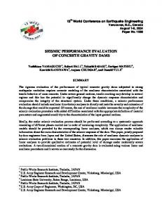
Fig. 8.1 The specimen under cyclic loading in the CNR-Ivalsa laboratory
The analyses were validated by means of three specimens removed from existing Pombaline edifices and tested under cycling horizontal loading. The DRAIN2DX software, developed by the University of California in Berkeley, was implemented with the Florence Pinching (Ceccotti, Lauriola, Follesa) to analyze, in a simplified way, structures characterized by timber frames. The researchers of the University of Florence introduced rotational semi-rigid elements to simulate pinching hysteretic behaviour of the joints based on cyclic tests results [4]. A similar quantitative investigative approach was carried out at the Earthquake Engineering Center in Peshawar, Pakistan. In fact, an equivalent model with elastic beam-column element, with assigned moment-rotation plastic hinges derived from an experimental campaign, was employed to obtain a non-linear static pushover tool by means of SAP2000 software and relative to Dhajji-Dewari structure, a timber braced frame masonry wall [5] (Fig. 8.1).
The Cycling Test Results Two specimens, timber framing with infill masonry frame and empty timber framing, which reproduce the Mileto panel in real scale, were tested at the CNR Ivalsa in Trento according to the UNI EN 12512:2003 “Timber structures—Test methods—Cycling testing of joints made with mechanical fasteners” protocol.
Fig. 8.2 a Hysteresis loops from the experimental survey; b empty timber frame and masonry wall reinforced with timber frame
The samples were tested with positive and negative horizontal displacements, applied at the top of the wooden framing, using an hydraulic actuator with a 500 kN capacity. A uniformly distributed load (18.7 kN/m) was applied to the models with the aim of replacing the self weight of the timber post king truss bearing on the wall of the Bishop’s building. The tests were interrupted at a maximum displacement of approximately 80 mm, as a consequence of excessive deformation. The specimen characterized by timber framing with masonry infill showed a low rocking mechanism with a maximum value of uplift displacement of 30 mm at peak load. The lateral resistance, relative to the first cycle, reached 103.64 kN in positive direction corresponding to a displacement of 59.18 mm (2.0 % drift) and −101.62 kN ultimate load in negative direction which is related to a displacement of −79.02 mm (2.6 % drift). Hence, the model showed an impairment of the strength, calculated between the first and the third cycle for each ductility level, variable between a peak of approximately 13 % in “compression” charge to a maximum value of approximately 15 % relative to a displacement of −40 mm. The energy dissipation value was approximately 1,500 kN mm in correspondence to the 1st half cycle with maximum displacement and approximately 300 kN mm for the half cycle concerning a displacement of 20 mm. The hysteresis equivalent damping ratio (Veq) presented constant values between 6 and 7 % for each displacement analyzed; even if a peak of 8.9 % was recorded relative to an “in-tension” displacement of 20 mm. The maximum ductility value (µ = Vu/Vy) reached by the tested model was 7.6. Namely the specimen has emphasized a ductility response (Fig. 8.2). The experimental survey pointed out a correct response of the Borbone constructive system under horizontal force. This kind of structure dissipated energy by means of interface frictions generated by the slips of the stones both between the infill masonry and the frame and also thanks to some fissures generated in the mortar, as well as the expulsion of a few stones. The overall timber skeleton, both elements and joints, acted, during the cycles, in elastic field (with the exclusion of
Seismic Performance Evaluation of Timber—Framed Masonry …
99
the beam at the frame bottom that presented some shear cracks, however without losing the structural integrity). The timber reinforcement provides the masonry with a major deformability and simultaneously the infill frame provides a confinement for the wooden structures. The model devoid of the infill masonry frame emphasized a weak behaviour characterized by a high deformability under cyclic actions. The main purpose of the experimental program described above is to provide data to assess seismic capacity of the Borbone system by means of multi-scale numeric modelling.
Preliminary Numerical Modelling The original software BrickWORK [6], specifically developed by some of the authors for the analysis of general masonry structures, is used in the herein numerical calculation to simulate the behaviour of the Baraccato constructive system, masonry wall reinforced with timber framing, under earthquake action. The numerical model is characterized by the masonry modelled by a collection of rigid blocks (bricks or stones) connected by mortar joints, where the elasticbrittle behaviour of the material is concentrated. Consequently, relying on these mechanical features, the main type of damage mechanism considered in the mortar joints is a tensile failure and until such a failure occurs, the joints are supposed to retain an elastic behaviour. Therefore, such an approach involves that the masonry, as a whole, has a good capability to carry compression loads and, taking into account that the masonry to which we want to refer is that of historical architecture heritage, the tensile strength of the material is limited to the poor cohesion between mortar and bricks. Based on the above assumptions, the mechanical characterization of masonry refers to a system of rigid blocks connected by unilateral contact and frictional links. In the numerical model the contact devices located in the joints are described by a set of fictitious links, arranged orthogonal to the interface surfaces, capable of transmitting only compressive forces or, at most, weak tensile forces which do not exceed the assigned limit values, and, by an additional link, tangent to the interface surface, to transmit the shear force. In the case of brittle-rigid joint only two normal links are strictly necessary. Instead, in the case of elastic-cracking joint it is better to consider at least four normal links in order to highlight the actual cracking pattern with the possibility of measuring the width and depth of the cracks inside the mortar joints. An example of this numerical model to a real case can be found in [7, 8] (Fig. 8.3). Moreover, it is reasonable to think that a model which considers the rigid blocks linked together by means of deformable surfaces, with no tension behaviour, is the most correct model to interpret the influences which the dimensions of the blocks and the orientation of the joints have on the behaviour
Fig. 8.4 Full-scale specimen of a masonry wall reinforced with a timber frame built according to the Borbone constructive system. Laboratories Ivalsa—CNR
of historical masonry buildings. In this way the model is capable of very clearly describing the progression of the damage to masonry under load conditions. The original numerical model, developed for the analysis of a structure consisting of only masonry blocks [9], has been modified to consider the peculiar mechanical characteristics of the Baraccato system, a masonry wall reinforced with a timber frames. Specifically, it was necessary to properly define the contact joint between wood and stone, which was assumed to have a no-tension, and the joint between wood and wood, which was considered to be perfectly elastic (Figs. 8.4 and 8.5). The results obtained from the experimental tests performed at the CNR–Ivalsa laboratory, on a full-scale specimen of a masonry wall made on the basis of the Borbone constructive system (summarized in Table 8.1) were used for calibrating the mechanical parameters to be assigned to the contact joints between the finite elements constituting the general mesh of the model. The first step was to define the mechanical and geometrical characteristics to be assigned to the discrete model with concentrated elasticity in correspondence to the joints so as to reproduce the same field of deformation and displacements obtained by the experimental tests carried out on the structure consisting of only a timber frame.
Seismic Performance Evaluation of Timber—Framed Masonry …
101
Fig. 8.5 Discrete model of the timber frame specimen
Table 8.1 Main results from the experimental survey relative to the compound specimen masonry with timber frame Direction P N
Fmax (kN) 103.6 −101.6
Vmax (mm) 59.2 −79.02
Fu (kN) 100.6 −101.6
Vu (mm) 79.12 −79.02
Envelope curve 1st cycle
The experimental survey showed that the timber frame, even at the maximum value of the applied load, never cracked in any section. For this reason no ultimate tensile and compressive strengths in correspondence to the wood joints have been defined because they can be conventionally assumed to be infinite. The next step was to define the discrete model of the masonry infill, taking into account the shape and the arrangement of the stone elements as well as the thickness of the joints so as to reproduce, as closely as possible, the actual experimental model. In order to define the mechanical characteristics of the contact joints between stone and wood, a zero tensile strength limit was assumed, while for the contact joints between the stones, an ultimate tensile strength equal to 0.5 MPa was considered. Relative to the boundary conditions of the mechanical model subjected to the numerical analysis, fixed supports were assumed at the base and a slider-type connection at the top, with the aim to reproduce the choices made for the experimental tests (Fig. 8.6). The results obtained with the numerical modelling have provided an interpretation of the behaviour of the wall very close, both quantitatively and qualitatively, to that of the specimen subjected to the cyclic tests in the laboratory (Fig. 8.7). The final results for a load, applied at the top, equal to 103.64 kN was achieved after 311 iterative steps of the calculation algorithm with a final horizontal displacement, measured at the top of the specimen, equal to 59.90 mm. Such a displacement is very close to the actual one. It is interesting to notice how, in terms of fracture and detachment, the crack pattern obtained by the numerical analysis has shown a significant similarity to the real one.
Fig. 8.6 Mechanical modelling of the masonry wall built according to the Borbone constructive system
Fig. 8.7 Ultimate deformed shape and cracking pattern. Comparison between experimental test and numerical model
Conclusion This paper provides a preliminary report on the experimental survey of the Baraccato system, a masonry wall reinforced with timber frames, as well as a preliminary numerical approach to analyzing this system based on a mechanical model composed of rigid blocks and elastic joints. The results of the analysis conducted by means of the original software BrickWORK, suitably modified to consider the presence of wooden elements, are perfectly coherent with the ones obtained by the cyclic tests of the Borbone system performed in the CNR-ivalsa laboratory. Acknowledgements The 2nd author wish to thank Regione Calabria for the economical support to realize the experimental campaign. Furthermore the authors are grateful to Libby Lee for her availability and advise for the editing of this paper.
Seismic Performance Evaluation of Timber—Framed Masonry …
103
References 1. Ruggieri, N., Tampone, G., Zinno, R.: Typical failures, seismic behavior and safety of the “Bourbon system” with timber framing. Advanced Materials Research, vol. 778, pp. 58–65. Trans Tech Publications, Switzerland (2013) 2. Kouris, S.L.A., Kappos, A.J.: Detailed and simplified non-linear models for timber-framed masonry structures. J. Cult. Heritage 13, 47–58 (2012) 3. Ramos, L.F., Lourenço, P.B.: Seismic Analysis of a Heritage Building Compound in the Old Town of Lisbon. In: 250th Anniversary of the 1755 lisbon earthquak (2005) 4. Ceccotti, A., Faccio, P., Nart, M., Sandhaas, C., Simeone, P.: Seismic behaviour of historic timber-frame buildings in the Italian Dolomites. In: ICOMOS International Wood Committee—15th International Symposium Istanbul and Rize (Turkey) 5. Naveed, A., Qaisar, A., Muhammad, U.: Seismic vulnerability assessment of multistory timber braced frame traditional masonry structures. Advanced Materials Research, vol. 601, pp. 168–172. Trans Tech Publications, Switzerland (2013) 6. Galassi, S., Paradiso, M.: BrickWORK software-aided analysis of masonry structures. In: IERI Procedia, Special Issue 2013 International Conference on Applied Computing, Computer Science, 2013 (in press) 7. Galassi, S., Paradiso, M., Tempesta, G., Zerboni, D.: The medieval bridge over the Rignalla brook near Florence: Analysis and rehabilitation project. In: International Journal EDA— Esempi di Architettura (2013) 8. Galassi, S., Paradiso, M., Tempesta, G.: X-Vaults: A software for the analysis of the stability of masonry cross-vaults. J. Comput. Sci. Issues 9(2), 133–142 (2012) 9. Galassi, S., Paradiso, M., Tempesta, G.: Non linear analysis of masonry structures subjected to external settlements. Open J. Civil Eng. 3(2A), 18–26 (2013)