and blend them to create novel views. The success of ... onto the proxy and blending closest views in the style of. Unstructured .... views on the line joining the optical centers of two ..... call that the 3D points in Pi of each image Ii project to the.
Volume 30 (2011), Number 4
Eurographics Symposium on Rendering 2011 Ravi Ramamoorthi and Erik Reinhard (Guest Editors)
Silhouette-Aware Warping for Image-Based Rendering Gaurav Chaurasia1 , Olga Sorkine2 ,George Drettakis1 1 REVES/INRIA 2 ETH
Sophia Antipolis, France Zurich, Switzerland
Abstract Image-based rendering (IBR) techniques allow capture and display of 3D environments using photographs. Modern IBR pipelines reconstruct proxy geometry using multi-view stereo, reproject the photographs onto the proxy and blend them to create novel views. The success of these methods depends on accurate 3D proxies, which are difficult to obtain for complex objects such as trees and cars. Large number of input images do not improve reconstruction proportionally; surface extraction is challenging even from dense range scans for scenes containing such objects. Our approach does not depend on dense accurate geometric reconstruction; instead we compensate for sparse 3D information by variational image warping. In particular, we formulate silhouette-aware warps that preserve salient depth discontinuities. This improves the rendering of difficult foreground objects, even when deviating from view interpolation. We use a semi-automatic step to identify depth discontinuities and extract a sparse set of depth constraints used to guide the warp. Our framework is lightweight and results in good quality IBR for previously challenging environments. Categories and Subject Descriptors (according to ACM CCS): Generation—Display algorithms;
1. Introduction Image-based rendering (IBR) [DTM96, LH96, GGSC96] is a powerful approach to easily capture and display 3D environments from photographs. Recent advances in computer vision and geometry processing make it possible to take 10-20 photographs, use automatic camera calibration [SSS06] and multi-view stereo to obtain dense depth/disparity maps [GSC∗ 07, FP09]. A final surface reconstruction step [KBH06] can then be used to merge these depth maps. The resulting approximate 3D geometry or proxy can be rendered by re-projecting the input photographs onto the proxy and blending closest views in the style of Unstructured Lumigraph Rendering (ULR) [BBM∗ 01]. This method combines recent vision techniques with ULR to achieve what we believe is the best result possible in our context, using existing solutions. Nonetheless, the solutions described above still have several limitations. First, multi-view stereo and reconstruction approaches have difficulty producing 3D geometry of sufficiently good quality for foreground objects with complex shapes such as trees, or sharp depth discontinuities such as vehicles parked in front of façades. Such situations are very frequent, especially in urban scenes. Consequently, IBR approaches that rely on accurate geomc 2011 The Author(s)
c 2011 The Eurographics Association and Blackwell PublishComputer Graphics Forum ing Ltd. Published by Blackwell Publishing, 9600 Garsington Road, Oxford OX4 2DQ, UK and 350 Main Street, Malden, MA 02148, USA.
Computer Graphics [I.3.3]: Picture/Image
etry can suffer from artifacts for such scenes. Second, most recent fully image-based methods which can handle complex scenes [SLW∗ 08,MHM∗ 09], have been developed only for small “baselines” and most often operate on paths interpolating input camera positions and orientations. Lastly, for many cases it is possible to improve the quality of 3D reconstruction by taking more images. However, for complex foreground objects reconstruction often does not improve, while leading to more “heavyweight” capture. We present a new approach which addresses these limitations. Our central idea is to compensate for incorrect or incomplete geometric information by introducing silhouetteaware variational warping [SS09]. We focus on scenes containing complex foreground geometry that is hard to reconstruct and on wide baseline IBR, i.e., with a large camera displacement between photographs. We first manually select important depth discontinuities, or silhouettes, and generate a uniform reconstructed point cloud for each image which guide our silhouette-aware warp. We thus preserve important depth discontinuities during the warp operation by letting parts of the mesh around the silhouettes become very “elastic”. Finally, we present an efficient multi-pass rendering algorithm which blends the
G. Chaurasia, O. Sorkine, G. Drettakis / Silhouette-Aware Warping for IBR
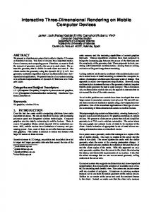
Figure 1: (a) We use 10-20 input photographs and multi-view stereo to create a dense 3D point cloud. (b) With our user-assisted point pre-processing the user designates important silhouettes and we reduce the cloud to ∼6,000 points per image. (c) The silhouettes and 3D point cloud guide a silhouette-aware warp, applied to 4 images at each frame. (d) Our renderer generates a high-quality final image which handles hard cases such as trees and other foreground objects. (e) Compared to previous geometry-based methods, many artifacts are removed.
warped images. We define appropriate weights for elastic vs. non-elastic parts of blended images, and post-process to provide a trade-off between blurring and color discontinuities. Previous approaches [DRE∗ 10, DCC∗ 09] directly reproject warp mesh vertices into a novel view, resulting in a “hard warp”. Such approaches require dense depth maps [DRE∗ 10] or warp mesh vertices tracked over time [DCC∗ 09]. Since our setting typically has sparse or unreliable depth information, temporal jumping artifacts ensue [LGJA09]. To avoid these artifacts, we use a variational warp with sparse depth information as guiding constraints. Mesh cutting is used to handle occlusion in hard warps [DCC∗ 09]. Such a solution is however inapplicable with smooth variational warping, which is why we introduce a silhouette-aware formulation (see Sect. 2 for further discussion). Our main contributions can be thus summarized as follows: • The representation consisting of sparse depth constraints and silhouette edges, which enables depth-preserving variational warping for wide-baseline IBR. • The introduction of silhouette-aware warping for IBR in which “elastic” edges absorb distortions while depth discontinuities are preserved. • An efficient rendering algorithm with a good trade-off between blurring and color discontinuities. Our approach greatly reduces artifacts compared to the best combination of state-of-the art reconstruction and IBR techniques, while overcoming the limitations discussed above (see results Fig. 7). In particular we treat scenes with hard-to-reconstruct objects and viewing paths which do not interpolate the input cameras. Finally, only a small number of images is required, resulting in a lightweight capture process.
2. Previous Work The earliest work in image-based rendering (IBR) did not use any geometric information about the scene [MB95, LH96] and depended on a large number of input images to avoid rendering artifacts. Other approaches such as the Lumigraph [GGSC96] and view-dependent texture mapping [DTM96] used an approximate geometric proxy to create novel views with fewer input images. Unstructured Lumigraph (ULR) [BBM∗ 01] generalized this to arbitrary unstructured input cameras; this method remains the most general free-viewpoint IBR algorithm. Modern graphics hardware can be used to enhance ULR by per-pixel blending and visibility handling [EDM∗ 08]. The results improve dramatically with better geometric reconstruction. Consequently, there has been a lot of recent work coupling 3D reconstruction and IBR, mainly focusing on developing more accurate geometric proxies. Multi-view stereo. A detailed survey of multi-view stereo algorithms is described in [SCD∗ 06]. The development of structure-from-motion for automatic camera calibration [SSS06] has further accelerated multi-view stereo research. Goesele et al. [GSC∗ 07] extract dense depth/disparity maps from input images which then can be merged using surface reconstruction techniques, e.g., Poisson reconstruction [KBH06]. Patch-based multi-view stereo [FP09] is one of the most general multi-view stereo algorithms which extracts 3D point clouds for all classes of scenes: outdoor, objects, indoors, etc. Hornung and Kobbelt [HK09] propose a generalized approach for stereo reconstruction and rendering on the GPU, avoiding the need for an explicit proxy. However, their method effectively builds on standard stereo reconstruction; complex scenes with wide baselines thus become hard to handle. Another class of algorithms has been developed specifically for IBR applications. Piecewise-planar reconstrucc 2011 The Author(s)
c 2011 The Eurographics Association and Blackwell Publishing Ltd.
G. Chaurasia, O. Sorkine, G. Drettakis / Silhouette-Aware Warping for IBR
tion [SSS09] and Manhattan-world priors [FCSS09] have been used for improved IBR. These approaches bypass surface reconstruction and produce lightweight proxies consisting of planes. However, they often have difficulties for scenes with non-planar or irregular geometry, or complex foreground objects, such as vehicles or trees. Image interpolation. Image interpolation has been used to transform two neighboring images of the same scene separated in space and/or time to generate in-between images without any 3D scene information. Chen and Williams [CW93] interpolated dense optical flow between input images, Seitz and Dyer [SD96] generated target views on the line joining the optical centers of two input views assuming no occlusions, and Lhuillier and Quan [LQ99] interpolated matched image regions. More recently, perceptually-motivated image interpolation was described in [SLW∗ 08] and spatio-temporal view interpolation was presented in [LLB∗ 10]. A high-quality approach for interpolating two images is presented in [MHM∗ 09]; they preserve frequency content of images by using graph-cut to create seamless transitions. These approaches are powerful and robust but require a very small baseline between images. Mahajan et al. [MHM∗ 09] report a 30-pixel maximum baseline, with 2D correspondences becoming unreliable beyond this limit. Moreover, they are restricted to view interpolation paths. IBR has been used in a different context in [SSS06] for navigating photo collections. This is further generalized to video navigation in [BBPP10] which uses scene geometry and foreground segmentation to reduce artifacts on the salient scene object (e.g., performer) during view interpolation. Reconstructed point clouds are used in [GAF∗ 10] for wide baseline view interpolation of prominent scene object. Their goal is to generate visually pleasing transitions in an image sequence rather than photo-realistic novel views of the whole scene. Image warping. Modifying the image content by means of warping has been used for morphing, image editing, artistic manipulation [CAA10] and re-targeting [SS09]. In variational warping, an objective functional is formulated according to the image content and the desired goal. Such goals can be preservation of salient features while resizing [GSCO06] or attaining an optimal disparity for a stereo image pair [LHW∗ 10]). This functional is then optimized on a grid mesh overlaid on the image subject to boundary constraints. So far, mostly 2D constraints (e.g., new boundary dimensions) have been employed; in contrast, we use reconstructed 3D points to guide the global warp. A related approach that uses reprojected 3D constraints is the video stabilization technique of [LGJA09], which warps frames of an input video to a novel viewpoint that lies on a smoothed camera path. However, their approach requires small baseline warping without (dis)occlusions. Our technique includes a novel silhouette-aware warp formulation to c 2011 The Author(s)
c 2011 The Eurographics Association and Blackwell Publishing Ltd.
handle these cases which are very common for wide-baseline warping. Further differences are discussed in Sec. 5.2. When dense, per-pixel depth [DRE∗ 10] is available or mesh vertices are tracked across successive frames [DCC∗ 09] direct re-projection into the novel view can be used. This gives a “hard warp” (see also Sect. 1). However, in our wide baseline multi-view setting, mesh vertices may not be reliably reconstructed in neighboring views. and thus hard warps result in jumping artifacts as observed in [LGJA09]. To provide smoother temporal effects, we use variational warping. In this variational warping context, we need to incorporate silhouettes and “elastic edges” to absorb distortion, to preserve complex foreground object shapes. The mesh cutting approach of [DCC∗ 09] would not work well with a variational approach. Specifically, it is impractical to set up a separate variational warp for each depth layer of scene since silhouettes are generally not closed and multiple objects would give too many separate layers for each image. In addition, special treatment, such as inpainting or texture synthesis would be necessary for all “cut” regions. 3. Overview The input to our method is a set of images calibrated using Bundler [SSS06] and a dense 3D point cloud generated using [FP09]. Our approach has three main steps (see Fig. 1): Pre-processing. Our approach first selects silhouettes around complex foreground objects (trees, cars, etc.) for each input image (Sec. 4.1). These silhouettes are used to correctly handle depth discontinuities. A 3D point cleanup step then decimates the dense multi-view stereo point cloud down to a sparse point cloud with uniform spatial distribution. This step also fills in poorly reconstructed regions using depth from neighboring points (Sec. 4.2). The resulting sparse point set provides stable constraints for our image warp. Silhouette-aware image warp. The points from each input image are mapped to their respective desired final positions by reprojecting them into the novel view. These act as guiding constraints for our image warp in the form of projection energy. A similarity transform energy prevents deformation of warp mesh triangles. We define “elastic” triangles around silhouettes which absorb the distortion because of depth differences. The last energy term minimizes warping artifacts that distort the shape of silhouettes (Sec. 5.2). Rendering. At any pixel we blend two images to get correct motion parallax and fill in disoccluded regions. We define appropriate weights to correctly diminish the visual impact of strong distortion produced by the elastic edges around the silhouettes. Finally, we use an optional Poisson synthesis step to alleviate seams. Our image warping works for poorly reconstructed ob-
G. Chaurasia, O. Sorkine, G. Drettakis / Silhouette-Aware Warping for IBR
jects because the silhouettes segment the image into contiguous regions at different depths. The sparse but uniform reconstruction given by 3D point processing provides enough constraints for correct 2D warping of each region, resulting in significant quality improvement compared to methods which rely on accurate geometry. 4. Extracting the Silhouette and Sparse Constraint Representation Our approach requires pre-annotated silhouettes (Fig. 2(a)) and uniform distribution of reconstructed points on each image (Fig. 2(a),(c)), both of which can be provided by a variety of approaches. Our core image-based rendering approach is independent of the methodology used for providing either of these.
direct manual edge marking. Please refer to supplementary material for a summary of our extensive tests and a comparison of automatic methods with manual authoring. In view of the above, we prefer manual silhouette authoring over a combination of segmentation and user intervention. Manual authoring took 40-60 seconds for each image in our datasets (see video). This is much faster compared to the time needed to manually create pixel-accurate geometry by hand. For objects such as trees, such geometry creation would require a skilled and experienced modeler and even then would probably require hours of work. We expect that the silhouette extraction step can be largely automated with advances in the state of the art (see discussion in Sec. 8).
4.2. 3D Point Selection
(a)
(b)
(c)
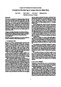
The goal of this step is to retain a uniform distribution of 3D points over the image, fill regions that have few or no points and remove erroneous points near silhouettes or specular regions.
Figure 2: (a) Silhouettes marked at sharp depth differences; (b) Original reconstructed point cloud with 118,049 points; (c) Sparse uniform point cloud with 6324 points selected by our approach. Note the regions with no original 3D points are also filled with new points (see Sec. 4.2).
We select a uniform spatial distribution by splatting the points on the image with a large splat size (21 × 21 or more) and select the suitably-sized subset of points which cover the largest number of pixels. This approach gives regularly spaced points. Poorly reconstructed regions such as holes in the point set are filled by adding new points placed at the depth of nearest available point.
4.1. Silhouette Selection
To avoid mixing foreground and background points on either side of the silhouettes, our approach conservatively removes all existing points within a small distance of silhouettes and replaces them with points using the depth from their respective side. This ensures that the silhouettes clearly separate points with different depths. We observed that such narrow regions are too small to contain significant depth gradients. Hence, this does not compromise warp accuracy. It is important to note that the newly added points are generated on a per-image basis and have no correspondence across images. As such, they are not true 3D points and do not augment the reconstruction. They simply provide constraints for stabilizing the image warp described next.
Silhouettes can be manually authored in each input image or computed (semi) automatically. Modern image segmentation algorithms [AMFM11] can be used to extract image boundaries automatically. Considering the importance of silhouettes for a variety of applications (object recognition, 3D reconstruction etc.), segmentation techniques have been adapted for extracting silhouettes or occlusion boundaries from a single image [HSEH07] or motion sequences [SH09, HY10]. Even though the edge maps returned by these approaches are impressive, they often have many false positives which need to be removed manually and missing edges have to be manually added. In addition, edge-maps have to converted to binary maps using a dataset dependent threshold. Then, they need to be converted into polygonal curves using chaining [TC89] and line segment decomposition by Douglas-Peucker algorithm [DP72]. Noisy edge-maps such as those in our scenes can make polygonal approximation ambiguous. We have experimented with such approaches extensively, both by applying them directly, and developing direct extensions. We observed that, in practice, segmentation followed by same degree of user interaction does not give the same accuracy as manual authoring and can actually be longer than
Some regions such as specular surfaces have incorrect 3D points, which are removed manually. This step is required only if a large number of incorrect 3D points are observed in a certain region. In our examples, the reconstruction produced 120K-200K points. Using the process described above, we retained 5-6K points for each image, which we call the set Pi . We observed that 6-9K points did not improve the warp quality and less than 3K points led to warping artifacts. The optimal number of points depends on desired output image resolution. A higher desired level-of-detail would require more constraints c 2011 The Author(s)
c 2011 The Eurographics Association and Blackwell Publishing Ltd.
G. Chaurasia, O. Sorkine, G. Drettakis / Silhouette-Aware Warping for IBR
for the warp, hence more points.The entire process, including user interaction (if needed), took about 4 minutes for a dataset of 15 images. For more implementation details, please refer to supplementary material. 5. Image Warping using 3D Constraints Given a novel view, expressed by a camera projection matrix Cn , our goal is to warp the input images I1 , I2 , . . . , IN so that they match the actual scene as it would have appeared in that view as faithfully as possible. We then use the warped images in the IBR pipeline (Sec. 6). Denote by Ci the camera projection matrix of input image Ii . If we knew the mapping Ui from every pixel q ∈ Ii to the corresponding 3D point p ∈ R3 that is captured in this pixel (Ci (p) = Ci (Ui (q)) = q), then the warp of image Ii into the new view would be simply W = Cn ◦Ui .
(1)
However, we do not have a dense per-pixel 3D reconstruction of the scene. On the contrary, we wish to use only a small set of 3D points that suffices for effective image warping. We therefore replace the per-pixel warp above with a sparse set of constraints on pixel positions and a warp prior that dictates the warping function to be smooth (except where (dis)occlusions happen) and locally preserve the shape of the image content. We handle occlusions by explicitly modeling the desired warp behavior along silhouettes, as will be described in Sec. 5.2. Together, the positional constraints and warp behavior priors define an energy functional E, and we find the warp that minimizes this energy using variational optimization. Setup. In order to compute the optimized variational warp, we discretize the image domain by overlaying a triangle mesh Mi on image Ii , with vertices Vi = {v1 , . . . , vNi } and faces Fi . We denote the warped vertex positions as v′j = W (v j ). The warp function W minimizes the energy functional E(W ) which we describe next. W is piecewise-linear (linear within each mesh face); therefore, to compute it we need to find the warped positions v′j . 5.1. Smooth Image Warping 3D constraints. Let Pi ⊆ R3 be the set of 3D points whose projected location in image Ii is known, obtained with the method of Sec. 4. For each point p ∈ Pi we have a corresponding 2D position q in the image, i.e., q = Ci (p). The 3D points should be projected correctly onto the novel view Cn ; therefore the warp should satisfy W (q) = Cn (p).
(2)
To formulate the above constraint in terms of the mesh vertices, denote the triangle that q belongs to by ( j, k, l) ∈ Fi , and let α(q), β(q), γ(q) be the barycentric coordinates of q c 2011 The Author(s)
c 2011 The Eurographics Association and Blackwell Publishing Ltd.
w.r.t. that triangle. The least-squares energy term for the 3D warp constraints is thus
2 � E p (W ) = ∑ α(q)v′j + β(q)v′k + γ(q)v′l −Cn (p) .(3) p∈Pi
We could have imposed Eq. (2) as a hard constraint by including the points q as vertices of the triangulation Mi ; however, as pointed out in [LGJA09], this can lead to temporal incoherence.
Similarity warp prior. To minimize the distortion caused by the warp, we would like W to be locally shape-preserving. We therefore use a similarity energy term, such that the transformation of each mesh triangle by W is as close as possible to a similarity transformation. Analogous energy terms were used in [LGJA09, ZCHM09, WLSL10]. Consider a mesh triangle a local � t = (v j , vk , vl ) and attach orthogonal frame to it: vk − v j , R90 (vk − v j ) , where R90 is a counterclockwise rotation by 90 degrees. Assume that v j is the origin of the local frame; vk can then be expressed simply as (1, 0) in the local coordinate system, and vl as some (a, b). If the triangle undergoes a similarity transformation, the local frame remains orthogonal and the coordinates of the triangle’s vertices remain the same. The similarity energy term can thus be expressed as
� 2 Es (W ) = ∑ v′l − a(v′k − v′j ) + b(R90 (v′k − v′j )) , (4) t∈Fi
where
a = (vl − v j )T (vk − v j )/kvk − v j k T
b = (vl − v j ) R90 (vk − v j )/kvk − v j k
(5) (6)
are computed from the original mesh. 5.2. Silhouette-aware Warp The energies E p and Es described so far are minimized by warp functions that are smooth and shape-preserving everywhere. However, we know that the warp should have discontinuities in the vicinity of object silhouettes because of the depth discontinuity there. When considering a small neighborhood around a silhouette edge, the warp may have a discontinuity perpendicular to the edge (to mimic (dis)occlusion) while remaining shape-preserving in the tangent direction. We model this behavior by conceptually inserting a narrow and highly elastic band parallel to the silhouette that is allowed to absorb heavy distortion due to discontinuity (see Fig. 3(b)). The shape of the silhouette itself, on the other hand, is preserved by adding a curve-similarity energy term described below, thus avoiding distortion of foreground objects. To properly discretize the image domain and formulate the silhouette-specific energy, we take all the silhouette polylines (obtained in Sec. 4) and duplicate them, offsetting the resulting parallel edges by 2 pixels (see Fig. 3(b)). The rest
G. Chaurasia, O. Sorkine, G. Drettakis / Silhouette-Aware Warping for IBR
(a)
(b) (a)
(b)
(c)
(d)
Figure 3: (a) Conforming triangulation used as warp mesh with constrained silhouette polylines shown in red. (b) Two parallel constrained polylines (shown in red) added for the silhouette polyline. Any three consecutive vertices on either of these polylines form an edgelet. The triangles wedged between these edges form the elastic band.
of the image domain is sampled uniformly, and we create a constrained conformal triangulation where the (doubled) silhouette edges are fixed (see Fig. 3(a)). All triangles between silhouette lines belong to the elastic band and are excluded from the energy term Es (Eq. (4)), thus allowing the band to be elastic. To preserve the shape of the silhouette itself, we require the silhouette curve to locally undergo a shape-preserving (i.e., similarity) transformation. The energy formulation is similar to Es , but it is defined on the silhouette curve this time, instead of a 2D domain. Consider three consecutive vertices lying on the curve, indexed w.l.o.g. as e = (v0 , v1 , v2 ). We call such a sequence of two curve edges an edgelet (see Fig. 3(b)). A similarity transformation of the edgelet e means that the angle θ between the two edges, as well as the length ratio kv0 − v1 k/kv2 − v1 k, remains the same. We can therefore write the curve similarity energy term as
2
′ kv0 − v1 k ′ � ′ ′�
R Eb (W ) = ∑ − v v − − v v θ 1 , (7) 2 1
0 kv2 − v1 k e∈E
Figure 4: Top row: An input image warped to different novel views without any silhouette handling. Bottom row: Same image warped to same views using our silhouette-aware discontinuous warp. The elastic band that absorbs all the distortion is shown in red.
plained in Sec. 6). Thus, our image warp is robust to widebaseline (dis)occlusion. 5.3. Total Warp Energy The optimal warp W minimizes the weighted sum of the 3D constraints, similarity, and silhouette energies (Eqs. (2), (4), (7)): E(W ) = w p E p + ws Es + wb Eb .
(8)
We use ws = 1, w p = wb = 2 in our implementation.
where E is the set of all edgelets and Rθ is the 2 × 2 rotation matrix that rotates the edge (v2 − v1 ) onto (v0 − v1 ). The effect of the above silhouette-aware discontinuous image warp is shown in Fig. 4. The smooth warp described in Sec. 5.1 will cause heavy distortion near depth discontinuities (see Fig. 4(a),(b)).
The energy E(W ) is quadratic in the unknown warped vertex positions v′ , therefore it has a unique minimum that is found by solving the sparse linear equation ∇E(W ) = 0. We use the direct sparse Cholesky solver TAUCS [Tol03]. Note that the system matrix does not change for different desired views Cn since only the right-hand side of the linear system changes. We therefore precompute the matrix factorization and only perform back-substitutions at runtime, which is very efficient.
Liu et al. [LGJA09] use energies E p and Es alone and would allow homogeneous distribution of the heavy distortion over the entire image. In contrast, our silhouette-specific energy term Eb preserves the local shape of the silhouettes by absorbing all the distortion in the elastic band. When pixels become occluded, the elastic band enables accurate mesh fold-over along the silhouette. When pixels are disoccluded, the elastic band stretches without deforming the silhouette (shown in red in Fig. 4(c),(d)). These bands are later filled using texture from a different image in the final result (ex-
Warp optimization implementation. In our experiments, we found initial sampling on a 30×30 vertex grid to be sufficient for 800×600 pixel output frame resolution. This sampling is locally refined to insert the silhouette edges, as described above; we compute the final constrained conformal triangulation using CGAL [Rin10]. Every input image Ii has its own mesh and associated linear system; we thus employ OpenMP to warp multiple images on parallel cores. Finally, the warped meshes are rendered using texture coordinates as their original positions to create the warped images. c 2011 The Author(s)
c 2011 The Eurographics Association and Blackwell Publishing Ltd.
G. Chaurasia, O. Sorkine, G. Drettakis / Silhouette-Aware Warping for IBR
Figure 5: Rendering pipeline. (a) Warped images. (b) Composite textures R0 and R1 . Pixels from same warped image are shown in same color. (c) R generated by blending from R0 and R1 . (d) Poisson synthesis output R′ using R as initialization and gradient G from R0 .
6. Implementation and Rendering Our rendering approach has several similarities to ULR [BBM∗ 01]. For clarity we thus summarize this method here. ULR with per-pixel blending and visibility. A set of images with calibrated cameras and a geometric proxy are taken as input. For every pixel of a novel view, the corresponding 3D point p on the proxy is found. This point is used to select the input images used, and it is reprojected back into these images. The colors of the corresponding pixels are then blended together using weights that depend on the angle between the view vectors of the input and target views (Fig. 6(a)), as well as the distance to the proxy (see [BBM∗ 01] for exact details). In our approach the novel view is generated by first selecting a set W of 4 images which can be used for all pixels in the final image. We observed that 3-4 input images are sufficient to synthesize a novel view. We then warp these images to the target view using our warp formulation in Sec. 5. Recall that the 3D points in Pi of each image Ii project to the same position in the novel view. As a result, the warped images are well registered. Blending weights. For each pixel, we select the best two images for blending using a penalty scheme inspired by ULR [BBM∗ 01]. Consider pixel (x, y) of the novel view with center of projection cn and a warped input image Ii′ ∈ W whose center of projection is ci . Let pn (x, y) be the point where the ray shot from cn through pixel (x, y) intersects the scene geometry. The required geometry is generated by splatting all 3D points ∪Pi into the novel view; holes are avoided by extracting depth from a triangulation of Pi . Note that this geometry is typically much coarser than a geometric proxy generated by 3D reconstruction [FP09] and surface extraction [KBH06]. However, our approach is robust to geometric inaccuracies because geometry is only used to compute blending weights. We use the angle between (cn − pn (x, y)) and (ci − c 2011 The Author(s)
c 2011 The Eurographics Association and Blackwell Publishing Ltd.
(a)
(b)
Figure 6: (a) Diagram showing the angle θ used for Pang (Ii′ , x, y). (b) Warped image showing pixels outside the warp mesh Mi in blue and pixels inside elastic band in red.
pn (x, y)) as an angle penalty similarly to ULR (see Fig. 6(a)). We also define a “field of view” penalty that checks whether the pixel lies inside the warp mesh Mi of Ii′ (shown in blue in Fig. 6(b)). Our last term penalizes elastic band pixels because the texture in such regions is expected to be heavily distorted (shown in red in Fig. 6(b)). Pang (Ii′ , x, y) = arccos (hcn − pn (x, y), ci − pn (x, y)i) � ∞ if (x, y) lies outside Mi , Pfov (Ii′ , x, y) = 0 otherwise � ∞ if (x, y) lies inside elastic band, Pe (Ii′ , x, y) = 0 otherwise The final penalty is P(Ii′ , x, y) = Pang (Ii′ , x, y) + Pfov (Ii′ , x, y) + Pe (Ii′ , x, y). (9) We create two textures R0 and R1 , where R0 is composed of pixels having the lowest penalties from all warped images Ii′ ∈ W and R1 the second lowest. A patch is a contiguous block of pixels looked up from the same warped image. The patches constituting R0 and R1 are shown in different colors in Fig. 5. Blending weights are calculated from penalties and stored in the alpha channels of R0 and R1 , respectively. The weights correspond to those used in the original ULR ap-
G. Chaurasia, O. Sorkine, G. Drettakis / Silhouette-Aware Warping for IBR
proach, with the addition of a factor 0 < Ψ ≤ 1: P(R0 , x, y) , P(R1 , x, y) P(R1 , x, y) = 1 − Ψ. wR1 (x, y) = 1 − Ψ P(R1 , x, y)
clusion artifacts because the proxy used for creating visibility maps is erroneous.
wR0 (x, y) = 1 − Ψ
Dataset (10)
The textures R0 and R1 are alpha-blended to give the texture R. The factor Ψ amplifies the difference in the penalties of R0 and R1 . For example, Ψ = 1 would cause wR1 to always remain 0. If the ratio of penalties P(R0 ):P(R1 ) is 1:2, setting Ψ = 0.87 would cause the ratio of weights wR0 :wR1 to become 4.33:1. This greatly reduces the contribution of R1 everywhere except where its penalty is very close to that of R0 . In all examples presented here, we have used Ψ = 0.87, which gives good results in all our examples. Poisson synthesis. The blended texture R may have spatial discontinuities: the patch boundaries or seams of R0 and R1 may remain visible, especially the elastic band regions where the texture originates from an image with substantially different view. To create a better final output image, we use Poisson synthesis to essentially inpaint the seam areas more gracefully. We create the gradient map G from R0 , and its divergence map divG. Note that the gradient inside any patch of R0 is the same as the gradient of the original image, which is important to retain crisp detail. We force the gradient of the final image R′ to 0 for all pixels lying on patch boundaries B0 of R0 , which amounts to smooth completion of those areas. Thus, we solve the following Poisson equation: (11) ∇2 R′ = divG subject to ∇R′ B = 0. 0
We do not pose explicit Dirichlet conditions but rather initialize the solver with the blended image R and perform a few Jacobi iterations. This suffices, since the initial guess is very close to the solution. This (optional) Poisson synthesis step alleviates spatial artifacts, while initialization with R helps temporal coherence. This can be seen in the inset of Fig. 5 (right). Our approach thus prefers smooth spatiotemporal transitions over blending more images, which leads to ghosting [MHM∗ 09].
7. Results To provide fair comparisons, we have combined state of the proxy reconstruction with the best set of techniques available for free viewpoint, wide-baseline IBR. In particular, we extend ULR to use per-pixel blending on the GPU, in contrast to vertex blending used in the original method [BBM∗ 01]. We have also added a recent visibility checking algorithm [EDM∗ 08] to further improve quality. In what follows, we call this method IULR for "Improved" ULR. Given the lack of accurate geometry for foreground objects, IULR results have ghosting artifacts and incorrect occlusion handling. Visibility checking does not alleviate oc-
Castle-P30 Street-10 Tree-18 Aquarium-20 Yellowhouse-12
Best proxy 49.1 MB 25.3 MB 21.2 MB 32.9 MB 26.0 MB
Same-size proxy 4.7 MB 3.6 MB 3.0 MB 15.4 MB 20.0 MB
Our approach 2.5 MB 1.5 MB 3.1 MB 2.9 MB 1.8 MB
Table 1: Storage for the proxy (used by IULR) and our approach. Proxy sizes are meshes (vertices/faces, no normals/colors/texture coordinates) in ASCII ".obj" format. Storage. Our method requires the storage of 5-6k points per image. In contrast, detailed proxies can be quite large for complex scenes with trees etc. (see Table 1). In our analysis, we compare to a “best proxy” which is the geometry of highest resolution and quality that could be extracted from the dataset, and to “same-size proxy” i.e., a proxy of similar size to our storage requirements, We have tested our approach on challenging datasets which cannot be reconstructed accurately. Castle-P30 is a standard multi-view stereo dataset [SvHG∗ 08] with a foreground object (tractor) in very wide baseline images. Piecewise-planar reconstruction [SSS09] gives unacceptable artifacts on the tractor. Aquarium-20 has multiple foreground objects at different depths, which are known to be difficult to handle [MHM∗ 09]. Street-10 and Tree-18 show our results for general urban scenes with vehicles and trees. The Tree18 dataset had many incorrectly reconstructed points on the tree, which were manually removed. The presence of vegetation makes 3D reconstruction and surface extraction very difficult; manually modeling such scenes is also very difficult and tedious. The baselines in our datasets vary from 275 pixels (14% of image height) in Aquarium-20; 260 pixels (16%) in Street-10 to 530 pixels (24%) in Castle-P30. With minimal user input, our approach generates much improved quality novel views from a free-viewpoint camera path even for poorly reconstructed datasets. Performance. We tested our method on an Intel Xeon (2.8 Ghz) running Windows 7 with NVIDIA Quadro 6000. Setting up the warp mesh and factoring the linear system for each input image with TAUCS takes 2-13 seconds. At run time, warping 4 input images on parallel cores takes 8-22 ms. The overall frame rate is 15 FPS with Poisson synthesis and 30-35 FPS for 1600×1200 size render targets. 8. Discussion and Future Work The results show that overall, our approach has significantly fewer disocclusion and ghosting artifacts compared to Improved ULR, even when the “best proxy” is used. With “same-size proxy” the improvement is more pronounced. This indicates two advantages of our method: (i) limited user c 2011 The Author(s)
c 2011 The Eurographics Association and Blackwell Publishing Ltd.
G. Chaurasia, O. Sorkine, G. Drettakis / Silhouette-Aware Warping for IBR
Figure 7: Top two rows: “best proxy” IULR (right) compared to our results (left) for novel views. From top to bottom, left to right: Castle-P30, Street-10, Aquarium-20, Tree-18. Last row: Yellowhouse-12: ours, “same-size” and “best” proxy. interaction and silhouette-aware warp enable greatly reduced artifacts compared to previous methods, especially for challenging scenes, and (ii) our solution is very compact. We believe that the introduction of silhouette-aware warping for IBR breaks new ground, and will hopefully have applications in other image-related tasks. In particular, we have demonstrated how to introduce content preserving discontinuities in a smooth variational warp. Our framework provides a trade-off between 2D image warping and 3D reconstruction. The method is robust to inaccurate geometric detail, since, other than the original (reliable) 3D reconstructed points, we only use geometry to compute blending weights. In contrast, existing techniques use the geometry to fetch texture from input images, making them sensitive to small geometric inaccuracies. Limitations and Future Work. Our approach does not handle transparent or see-through objects such as railings, as our discontinuous warp expects somewhat contiguous objects. However, such transparent objects cannot be handled within any other IBR framework that uses geometry because depth estimation and surface reconstruction become very challenging for such cases. Our blending strategy favors using a single image than blending heavily. This causes occasional temporal popping especially on non-lambertian surfaces which appear different in different views. On the other hand, excessive blending alleviates popping but synthesized images are not crisp. Adaptive blending weights based on image content, in conjunction with 3D geometry is a promising research direction to address this limitation. c 2011 The Author(s)
c 2011 The Eurographics Association and Blackwell Publishing Ltd.
Our discontinuous warp works best for contiguous foreground objects, though we do demonstrate results for narrow objects such as tree trunks. Similar objects (e.g., lamp posts) can be handled more robustly with an adaptive-resolution warp mesh in regions with many silhouettes, as opposed to our uniform mesh. Finally, there is scope for completely automating the silhouette extraction step, which would make our approach applicable to larger and more complex scenes. Our experiments with existing approaches (e.g., [SH09, HY10, AMFM11]) show that direct or obvious extensions of these methods do not provide adequate solutions. We consider this to be an interesting and self-contained research problem, since it would provide a new “multi-view” segmentation approach for wide-baseline image sets. Promising directions include the use of available depth and correspondence cues to eliminate false matches (see supplementary material), and automatic propagation of potentially manual silhouette information from one image to all other images in the dataset. 9. Acknowledgments The authors acknowledge the support of the INRIA ARC NIEVE project, NVIDIA (Professor partnership program), Adobe Systems (research gift), Autodesk (Maya donation) and NSF award IIS-0905502. References [AMFM11] A RBELAEZ P., M AIRE M., F OWLKES C., M ALIK J.: Contour detection and hierarchical image segmentation. IEEE
G. Chaurasia, O. Sorkine, G. Drettakis / Silhouette-Aware Warping for IBR Trans. Pattern Anal. Mach. Intell. to appear (2011). [BBM∗ 01]
B UEHLER C., B OSSE M., M CMILLAN L., G ORTLER S., C OHEN M.: Unstructured lumigraph rendering. In Proc. SIGGRAPH (2001), pp. 425–432.
[BBPP10] BALLAN L., B ROSTOW G. J., P UWEIN J., P OLLE FEYS M.: Unstructured video-based rendering: Interactive exploration of casually captured videos. ACM Trans. Graph (July 2010), 1–11. [CAA10] C ARROLL R., AGARWALA A., AGRAWALA M.: Image warps for artistic perspective manipulation. ACM Trans. Graph. 29 (July 2010), 127:1–127:9. [CW93] C HEN S. E., W ILLIAMS L.: View interpolation for image synthesis. In Proc. SIGGRAPH (1993), pp. 279–288. [DCC∗ 09] D URAND F., C OHEN M., C HEN J., PARIS S., WANG J., M ATUSIK W.: The Video Mesh: A Data Structure for Imagebased Video Editing. Tech. Rep. MIT-CSAIL-TR-2009-062 (accepted to ICCP 2011), MIT CSAIL, 2009. [DP72] D OUGLAS D., P EUCKER T.: Algorithms for the reduction of the number of points required to represent a digitized line or its caricature. The Canadian Cartographer 10, 2 (1972). [DRE∗ 10]
D IDYK P., R ITSCHEL T., E ISEMANN E., M YSZKOWSKI K., S EIDEL H.-P.: Adaptive image-space stereo view synthesis. In Vision, Modeling and Visualization Workshop (Siegen, Germany, 2010), pp. 299–306.
[DTM96] D EBEVEC P. E., TAYLOR C. J., M ALIK J.: Modeling and rendering architecture from photographs: A hybrid geometry and image-based approach. Proc. SIGGRAPH (1996). [EDM∗ 08] E ISEMANN M., D ECKER B. D., M AGNOR M., B EKAERT P., DE AGUIAR E., A HMED N., T HEOBALT C., S EL LENT A.: Floating Textures. Comput. Graph. Forum (Proc. Eurographics) 27, 2 (4 2008), 409–418. [FCSS09] F URUKAWA Y., C URLESS B., S EITZ S. M., S ZELISKI R.: Manhattan-world stereo. In Proc. CVPR (2009), pp. 1422– 1429. [FP09] F URUKAWA Y., P ONCE J.: Accurate, dense, and robust multi-view stereopsis. IEEE Trans. Pattern Anal. Mach. Intell. 32, 8 (2009), 1362–1376. [GAF∗ 10]
G OESELE M., ACKERMANN J., F UHRMANN S., H AUBOLD C., K LOWSKY R., DARMSTADT T.: Ambient point clouds for view interpolation. ACM Trans. Graph. 29 (July 2010), 95:1–95:6.
[GGSC96] G ORTLER S. J., G RZESZCZUK R., S ZELISKI R., C O HEN M. F.: The Lumigraph. In Proc. SIGGRAPH (1996), pp. 43–54. [GSC∗ 07] G OESELE M., S NAVELY N., C URLESS B., H OPPE H., S EITZ S. M.: Multi-view stereo for community photo collections. In Proc. ICCV (2007), pp. 1–8. [GSCO06] G AL R., S ORKINE O., C OHEN -O R D.: aware texturing. In Proc. EGSR (2006), pp. 297–303.
Feature-
[HK09] H ORNUNG A., KOBBELT L.: Interactive pixel-accurate free viewpoint rendering from images with silhouette aware sampling. Comput. Graph. Forum 28, 8 (2009), 2090–2103. [HSEH07] H OIEM D., S TEIN A. N., E FROS A. A., H EBERT M.: Recovering occlusion boundaries from a single image. ICCV (2007), 1–8. [HY10] H E X., Y UILLE A.: Occlusion boundary detection using pseudo-depth. In Proceedings of the 11th European conference on Computer vision: Part IV (Berlin, Heidelberg, 2010), ECCV’10, Springer-Verlag, pp. 539–552.
[KBH06] K AZHDAN M., B OLITHO M., H OPPE H.: Poisson surface reconstruction. In Proc. SGP (2006), pp. 61–70. [LGJA09] L IU F., G LEICHER M., J IN H., AGARWALA A.: Content-preserving warps for 3D video stabilization. ACM Trans. Graph. 28 (2009), 44:1–44:9. [LH96] L EVOY M., H ANRAHAN P.: Light field rendering. In Proc. SIGGRAPH (1996), pp. 31–42. [LHW∗ 10] L ANG M., H ORNUNG A., WANG O., P OULAKOS S., S MOLIC A., G ROSS M.: Nonlinear disparity mapping for stereoscopic 3D. ACM Trans. Graph. 29, 3 (2010). [LLB∗ 10] L IPSKI C., L INZ C., B ERGER K., S ELLENT A., M AGNOR M.: Virtual video camera: Image-based viewpoint navigation through space and time. Computer Graphics Forum 29, 8 (2010), 2555–2568. [LQ99] L HUILLIER M., Q UAN L.: Image interpolation by joint view triangulation. In Proc. CVPR (1999), vol. 2. [MB95] M C M ILLAN L., B ISHOP G.: Plenoptic modeling: an image-based rendering system. In Proc. SIGGRAPH (1995), pp. 39–46. [MHM∗ 09]
M AHAJAN D., H UANG F.-C., M ATUSIK W., R A R., B ELHUMEUR P.: Moving gradients: A pathbased method for plausible image interpolation. ACM Trans. Graph. 28, 3 (2009). MAMOORTHI
[Rin10] R INEAU L.: 2D conforming triangulations and meshes. In CGAL User and Ref. Manual, 3.7 ed. CGAL Ed. Bd., 2010. [SCD∗ 06] S EITZ S. M., C URLESS B., D IEBEL J., S CHARSTEIN D., S ZELISKI R.: A comparison and evaluation of multi-view stereo reconstruction algorithms. In Proc. CVPR (2006), vol. 1. [SD96] S EITZ S. M., DYER C. R.: View morphing. In Proc. SIGGRAPH (1996), pp. 21–30. [SH09] S TEIN A. N., H EBERT M.: Occlusion boundaries from motion: Low-level detection and mid-level reasoning. Int. J. Comput. Vision 82 (May 2009), 325–357. [SLW∗ 08] S TICH T., L INZ C., WALLRAVEN C., C UNNINGHAM D., M AGNOR M.: Perception-motivated interpolation of image sequences. In Proc. APGV (2008), pp. 97–106. [SS09] S HAMIR A., S ORKINE O.: Visual media retargeting. In ACM SIGGRAPH Asia Courses (2009). [SSS06] S NAVELY N., S EITZ S. M., S ZELISKI R.: Photo tourism: exploring photo collections in 3D. ACM Trans. Graph. 25, 3 (2006), 835–846. [SSS09] S INHA S. N., S TEEDLY D., S ZELISKI R.: Piecewise planar stereo for image-based rendering. In Proc. ICCV (2009), pp. 1881–1888. [SvHG∗ 08] S TRECHA C., VON H ANSEN W., G OOL L. J. V., F UA P., T HOENNESSEN U.: On benchmarking camera calibration and multi-view stereo for high resolution imagery. In Proc. CVPR (2008). [TC89] T EH C.-H., C HIN R.: On the detection of dominant points on digital curves. IEEE Trans. Pattern Anal. Mach. Intell. 11, 8 (Aug. 1989). [Tol03] T OLEDO S.: TAUCS: A Library of Sparse Linear Solvers, version 2.2. Tel-Aviv University, Available online at http://www.tau.ac.il/~stoledo/taucs/, 2003. [WLSL10] WANG Y.-S., L IN H.-C., S ORKINE O., L EE T.-Y.: Motion-based video retargeting with optimized crop-and-warp. ACM Trans. Graph. 29, 4 (2010), article no. 90. [ZCHM09] Z HANG G.-X., C HENG M.-M., H U S.-M., M ARTIN R. R.: A shape-preserving approach to image resizing. Comput. Graph. Forum 28, 7 (2009), 1897–1906.
c 2011 The Author(s)
c 2011 The Eurographics Association and Blackwell Publishing Ltd.