AbstractâTo enable reliable data delivery and balance load in the presence of failures, ... each router is NP-hard, our extensive simulations on a tier-1. IP backbone .... end paths allows fast failure recovery as the ingress router can shift the load .... router), and hd is the flow requirement (measured traffic). The management ...
Simple Failure Resilient Load Balancing Martin Suchara∗ , Dahai Xu† , Robert Doverspike† , David Johnson† and Jennifer Rexford∗ ∗ Computer
Science Department Princeton University, NJ 08544 {msuchara, jrex}@cs.princeton.edu Abstract—To enable reliable data delivery and balance load in the presence of failures, we propose a new mechanism that combines path protection and traffic engineering. The key benefit of our solution is its simplicity, allowing for fast recovery while imposing minimal requirements on the routers. To provide resilience against every failure scenario from a known set, we advocate using a fixed set of parallel end-to-end paths for each traffic demand. Upon detecting a path failure, the ingress router uses a local rule to rebalance the outgoing traffic on the remaining available paths. We describe several candidate rebalancing algorithms, and analyze their performance. Although calculating the optimal set of paths and the path-splitting parameters for each router is NP-hard, our extensive simulations on a tier-1 IP backbone demonstrate that our easy-to-calculate heuristic suffices to achieve nearly optimal load balancing. We believe that a simple-to-implement solution with a fast recovery time, such as ours, will appeal to Internet Service Providers as well as the operators of data centers and enterprise networks.
I. I NTRODUCTION Failure recovery mechanisms [1] are used to ensure uninterrupted data delivery in the presence of link or router failures. Failure recovery is important for backbone network operators who strive to meet availability requirements of Service Level Agreements (SLAs), as well as the operators of large data centers where the failures of individual components are quite common. Failure recovery is a challenging problem because of the need for balanced load after rerouting the traffic affected by the failure. In addition, prompt failure handling and rerouting of the affected traffic to alternate paths often results in significant path restructuring, which is another major challenge faced by network operators who use the existing failure-recovery mechanisms. Our work proposes a fast failure-recovery mechanism that offers nearly optimal load balancing while using a static set of paths. We exploit multipath routing between each pair of ingress and egress routers. Such end-to-end routing has several benefits. First, these routes do not need to change when a failure is detected, which saves time, reduces overhead, and improves path stability. Second, end-to-end load balancing spreads the traffic in the network more effectively than local rerouting. Finally, it enables faster recovery and lower protocol overhead than conventional link-state routing protocols, like OSPF, which not only rely on flooding link-state advertisements and recomputing shortest paths but also suffer from transient forwarding loops. Another benefit of our solution is its simplicity, with most of the functionality incorporated in the network-management software rather than the network
† AT&T
Labs Research Florham Park, NJ 07932 {dahaixu, rdd, dsj}@research.att.com elements. The management software is responsible for selecting the end-to-end paths and calculating the path-splitting parameters for each router. Our design has a minimalist control plane, used only for failure detection, which leads naturally to a simpler network where smart, expensive routers are replaced with cheaper switches with a limited feature set. While our design enables the simplification of the network elements, our solution is also readily deployable using technologies available in existing routers. Multi-Protocol Label Switching (MPLS) [2] is particularly suitable because ingress routers encapsulate packets with labels and direct them over pre-established Label-Switched Paths (LSPs). This enables flexible routing when multiple LSPs are established between each ingress-egress router pair. Techniques for splitting traffic over the multiple LSPs, with relatively flexible splitting ratios, is already supported by the major router vendors [3], [4]. Our solution, then, could be viewed as a particular application of MPLS, where the network-management software computes the LSPs, instructs the ingress routers to establish the paths (say, using RSVP), and disables any dynamic recomputation of alternate paths when primary paths fail. In our architecture, the network-management software solves an offline optimization problem to compute the paths and the splitting ratios, given the traffic demands, the network topology, and known failure scenarios. The objective is to minimize congestion over all the failure scenarios, weighted by their likelihood or importance. The congestion for a particular failure case is determined as a sum of the congestion penalty associated with each link. Since calculating the optimal paths and splitting ratios is NP-hard, we propose several effective heuristics that vary in the functionality they expect from the network elements. The heuristics start with a common first step that solves a simple multicommodity flow problem to compute a small set of end-to-end paths. The heuristics differ in the second step, which optimizes the (static) router configurations that determine how traffic is split over multiple paths. We evaluate our solution experimentally in the context of MPLS on the IP backbone of a tier-1 ISP. We demonstrate that our heuristics are nearly optimal in balancing traffic load across a wide range of failure scenarios. We also show that the number of paths connecting each ingress-egress router pair is small, which is important for a scalable solution. Our simulation achieves a high degree of accuracy by utilizing the real topology, link capacities, link delays, traffic matrices, and Shared Risk Link Groups (SRLGs) [5] (indicating which links
2
are likely to fail together) of the tier-1 ISP. Our approach differs from previously published work. Most of the literature considers either path protection or traffic engineering [4] in isolation. MPLS path-protection mechanisms aim to reduce the failure-recovery time by establishing backup paths that carry traffic when the primary LSP fails. Local path protection [6] reserves a backup path connecting the ends of individual links in the network. While enabling fast recovery, local path protection cannot fully exploit the available path diversity, leading to suboptimal load balancing. Global path protection [7] allows better load balancing through the use of end-to-end backup LSPs, but the recovery is slow1 . Our approach addresses the optimality issue by utilizing dynamic traffic splitting across multiple diverse LSPs, and its recovery is faster than global path protection due to its simplicity. The paper is organized as follows. Following a brief overview of our proposed architecture in Section II, Section III formulates the optimizaton problem and Section IV presents several heuristic solutions. Next, Section V evaluates the heuristics on realistic topology and traffic data. The paper concludes in Section VII with a discussion of future research directions. NP-completeness proofs appear in the Appendix. II. L OAD BALANCING OVER M ULTIPLE S TATIC PATHS Our network architecture is motivated by the need to: (i) make network management easier and enable the use of simpler, cheaper routers, (ii) balance load before, during, and after failures to make efficient use of network resources, and (iii) detect and respond to failures quickly to ensure uninterrupted service. The resulting design places most of functionality in a management system that performs optimizations in an offline fashion, as depicted in Figure 1. The routers simply detect failed paths and automatically redistribute traffic on the remaining paths based on their static configuration. This simplifies network management, reduces router cost, and removes dynamic state from the routers. In this section, we discuss how ingress routers split traffic over multiple paths and learn about path failures, and how the management system pre-computes the paths and splitting ratios. A. Flexible Load Balancing Over Pre-established Paths Our architecture uses multiple paths between each ingressegress router pair in the network. Using preestablished end-toend paths allows fast failure recovery as the ingress router can shift the load away from the failed paths, avoiding dynamic path recalculation. Using multiple paths also allows the ingress router to balance the load in the network which helps to reduce congestion. In our architecture, the ingress router has a simple static configuration that determines the traffic-splitting ratios among the available paths, while intermediate routers merely forward packets over pre-established paths. As a result, our router is a simple device that does not need to collect congestion feedback, participate in a routing protocol, interact 1 Calculation of optimal backup LSPs and the switch over is so involved that ISPs are currently considering deployment of a hybrid scheme that applies local and global path protection in succession.
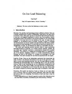
• topology design l d i • list of shared risks • demands
• fixed paths p • splitting ratios
t 0.5 0.5
s 0
link cut
Fig. 1. The management system calculates a fixed set of paths and splitting ratios, based on the topology, traffic demands, and potential failures. The ingress router learns about path failures and splits traffic over working paths.
with the management system upon failure detection, or solve any computationally difficult problems. In the context of MPLS, flexible traffic splitting is already supported by both major router vendors [3], [4]. The routers can be configured to hash packets based on port and address information in the headers into several groups and forward each group on a separate path. This provide path splitting with relatively fine granularity (e.g., at the 1/16th level), while ensuring that packets belonging to the same flow traverse the same path. In a data center, the end-host servers could encapsulate the packets, as suggested in [8], and choose encapsulation headers that split the traffic over the multiple paths with the desired splitting ratios. This further reduces the complexity of the network elements, and also enables finergrain traffic splitting than today’s routers provide. B. Path-level Failure Detection and Notification The ingress router uses a path-level failure-detection mechanism to avoid sending traffic on faileded path. This mechanism could be implemented, e.g., using Bidirectional Forwarding Detection (BFD) [9]. BFD establishes sessions between the ingress-egress router pairs to monitor each of the paths. BFD piggybacks on existing traffic and obviates the need to send “hello” messages. A major advantage of this approach is that the ingress router receives a faster failure notification than would be possible using a routing protocol’s own local keepalive mechanism. Another advantage is that the packets are handled by the hardware interfaces and do not use the router’s CPU time. Although the ingress router doesn’t learn which link failed, knowledge of end-to-end path failures is sufficient to avoid using the failed path. In fact, since our design does not require the routers to be aware of the topology, no control protocol is needed to exchange topology information2 . 2 A backwards-compatible realization of our architecture could leverage finer-grain topology information. For example, MPLS-capable routers can be configured to learn about link failures from the interior gateway protocol (e.g., OSPF). If no alternate routes are specified for the affected path(s), the router simply renormalizes the outgoing traffic on the remaining available paths.
3
C. Offline Route Optimizations in the Management System Given the static network topology, shared-risk information (i.e., sets of links with a shared vulnerability), and traffic matrix (i.e., volume of exchanged traffic between each ingressegress router pair), the management system calculates multiple diverse paths so that at least one of them works for each failure scenario; this is possible as long as no failure partitions the ingress-egress router pair. Moreover, the paths can be chosen so that they allow load balancing in the network. These two goals are complementary as both require path diversity. After computing the paths and associated traffic-splitting parameters, the management system installs them either by populating forwarding tables in the routers or configuring the ingress routers to signal the paths using a protocol like RSVP. The management system has direct access to accurate information about the network topology and anticipated traffic demands. The operator can easily provide the management system with a list of potential or planned failures; correlated link failures can be determined by considering sets of links that share a common vulnerability [5]. Many failures in ISP backbones are planned in advance, or involve a single link, and most of these faiulres are short lived [10]. Our solution allows the network to continue directing traffic over the working paths, without incurring any protocol overheads to “withdraw” or recompute paths; instead, the failed paths remain in the forwarding tables, ready to be used upon recovery. Since the network configuration is completely static, the management system can calculate paths and splitting parameters offline, and change them only in response to significant traffic shifts or the planned long-term addition or removal of equipment. III. N ETWORK M ODEL AND O PTIMIZATION O BJECTIVE The network-management system solves an offline optimization problem to select the paths and splitting ratios for each ingress-egress pair. The exact formulation of the optimization problem depends on how the network elements represent and use the splitting ratios. In this section, we present the common aspects of the problem formulation. First, we describe how we model the network topology, traffic demands, failure scenarios, and end-to-end paths. Then, we introduce the objective that the management system tries to optimize. Section IV presents the remaining details of the optimization problems, along with our algorithms for solving them. A. Topology, Shared Risks, Traffic Demands, and Paths As shown in Figure 1, the management system has three main inputs: Fixed topology: The topology is represented by a graph G(V, E) with a set of vertices V and directed edges E. The capacity of edge e ∈ E is denoted by ce , and the propagation delay on the edge is ye . Shared risks: The shared risks are denoted by the set S, where each s ∈ S consists of a set of edges that may fail together. For example, a router failure is represented by the set of its incident links, a fiber cut is represented by all links in the affected fiber bundle, and the failure-free case is represented
by the empty set ∅. For simplicity, we assume that all demands remain connected for each failure; alternatively, a demand can be omitted for each failure case that disconnects it. Traffic demands: Finally, each traffic demand d ∈ D is represented by a triple (ud , vd , hd ), where ud ∈ V is the traffic source (ingress router), vd ∈ V is the destination (egress router), and hd is the flow requirement (measured traffic). The management system’s output is a set of paths Pd for each demand d and the splitting ratios for each path. Optimizing these outputs must consider the effects of each failure state s on the paths available for demand d. Traffic splitting by ingress router ud depends only on which paths have failed, not which failure scenario s has occurred; in fact, multiple failure scenarios may affect the same subset of paths in Pd . To reason about the handling of a particular demand d, we consider a set Od of “observable” failure states, where each observable state o ∈ Od corresponds to a particular Pdo ⊂ Pd representing the available paths. For ease of expression, we let the function od (s) map to the failure state observable by node ud when the network is in failure state s ∈ S. The amount of flow assigned to path p in observable failure state o ∈ Od is fpo . The total flow on edge e in failure state s is les , and the s flow on edge e corresponding to demand d is le,d . TABLE I S UMMARY OF NOTATION Variable
Description
G(V, E) ce ye
network with vertices V and directed edges E capacity of edge e ∈ E propagation delay on edge e ∈ E
S s ws
family of network failure states network failure state (set of failed links) weight of network failure state s ∈ S
D ud vd hd
set of demands source of demand d ∈ D destination of demand d ∈ D flow requirement of demand d ∈ D
Pd αp
paths available to demand d ∈ D fraction of the demand assigned to path p
Od od (s) Pdo
family of observable failure states for node ud state observable by ud in network failure state s ∈ S paths available to ud in observable failure state o ∈ Od
fps fpo les s le,d
flow flow total flow
on path p in network failure state s ∈ S on path p in observable failure state o ∈ Od flow on edge e in network failure state s of demand d on edge e in network failure state s
B. Minimizing Congestion Over the Failure States The management system’s goal is to compute paths and splitting ratios that minimize congestion over the range of possible failure states. APcommon traffic-engineering objective [11] is to minimize e∈E Φ(les /ce ) where le is the load on edge e and ce is its capacity. Φ() could be a convex function of link load [11], to penalize the most congested links while still accounting for load on the remaining links. To place more
4
emphasis on the common failure scenarios, each failure state can be associated with a weight ws . To minimize congestion across the failure scenarios, the final objective function is obj(les11 /ce1 , ...) =
P
s∈S
ws
P
e∈E
Φ(les /ce ).
(1)
Minimizing this objective function is the goal in each of our optimization problems in Section IV. However, the constraints that complete the problem formulation differ depending on the functionality placed in the underlying routers. IV. O PTIMIZING THE PATHS AND S PLITTING R ATIOS The optimization problem the management system solves depends on the capabilities of the underlying routers. On one extreme, the network could support an optimal configuration of paths and splitting ratios for every network failure scenario s ∈ S. While not scalable in practice, the solution to this optimization problem serves as a performance baseline and as a way to compute a suitable set of paths Pd for each demand d. A more practical alternative is to have each ingress router ud store splitting ratios for every observable failure o ∈ Od . After observing the path failure(s), router ud would switch to the new splitting configuration for the remaining paths. An even simpler alternative is to have a single splitting configuration that is used across all failures. In this approach, router ud simply renormalizes the splitting percentages for the active paths. In this section, we present the management system’s algorithm for each of these three scenarios. Since several of the optimization problems are NP-hard (as proven in the Appendix), we use heuristics that (as shown in Section V) achieve nearly optimal performance in practice. A. Optimal Solution: Per Network Failure Sate The ideal solution would compute the optimal paths and splitting ratios separately for each failure state. To avoid introducing explicit variables for exponentially many paths, we formulate the problem in terms of the amount of flow s le,d from demand d traversing edge e for failure state s. The optimal edge loads are obtained by solving the following linear program: min s.t.
obj(les11 /ce1 , ...) P s les = d∈D le,d P P s s 0 = i:e=(i,j) le,d − i:e=(j,i) le,d P P s s hd = i:e=(u ,i) le,d − i:e=(i,u ) le,d d d s 0 ≤ le,d
∀s, e ∀d, s, j 6= ud , vd ∀d, s ∀d, s, e, (2)
s where les and le,d are variables. The first constraint defines the load on edge e, the second constraint ensures flow conservation, the third constraint ensures that the demands are met, and the last constraint guarantees flow non-negativity. An optimal solution can be found in polynomial time using conventional techniques for solving multicommodity flow problems. After obtaining the optimal flow on each edge for all the failure scenarios, we use a standard decomposition algorithm
to determine the corresponding paths Pd and the flow fps on each of them. The decomposition starts with a set Pd that is empty. New unique paths are added to the set by performing the following decomposition for each failure state s. First, s annotate each edge e with the value le,d . Remove all edges that have 0 value. Then, find a path connecting ud and vd . If multiple such paths exist, we use the path p with the smallest propagation delay. Although we could choose any of the paths from ud to vd , our goal is to obtain as short paths as possible. Add this path p to the set Pd and assign to it flow fps equal to the smallest value of the edges on path p. Reduce the values of these edges accordingly. Continue in this fashion, removing edges with zero value and finding new paths, until there are no remaining edges in the graph. Note that we can show by s induction that this process completely partitions the flow le,d into paths. The decomposition yields at most |E| paths for each network failure state s because the weight of at least one edge becomes 0 whenever a new path is found. Hence the total size of the set Pd is at most |E||S|. It is difficult to obtain a solution with a tighter bound as we prove in the appendix that it is NP-hard to solve problem (2) when the number of allowed paths is bounded by a constant J. The optimal solution solves the multicommodity flow problem, computes the resulting paths, and for each failure scenario s ∈ S assigns flow fps to path p ∈ Pd . However, this solution is not feasible in practice, because of the burden it imposes on the underlying routers. Each ingress router would need to store a splitting configuration for each failure scenario s. The number of failure states s can be quite large, especially when failure scenarios could involve multiple links. After a failure, the ingress router would need to learn which link(s) failed, identify the associated failure scenario s, and switch to the appropriate splitting configuration. This adds considerable complexity to the network elements. Yet, the optimal solution is still interesting, for two reasons. First, the solution provides an upper bound on the performance of the more practical schemes, enabling us to judge how effective they are. Second, the optimal paths and splitting ratios are a useful building block in computing the network configurations in our practical solutions.
B. State-Dependent Splitting: Per Observable Failure To reduce the complexity of the network elements, each ingress router ud could have a set of splitting ratios for each observable failure state o ∈ Od . Since the path-splitting ratios depend on which paths in Pd have failed, the the ingress router must store splitting ratios for min(|S|, 2|Pd | ) scenarios; fortunately, the number of paths |Pd | is typically small in practice. When the network performs such state-dependent splitting, the management system’s goal is to find a set of paths Pd for each demand and the flows fpo on these paths in all observable states o ∈ Od . If the paths Pd are known and fixed, the problem can be formulated as a linear program:
5
min s.t.
obj(les11 /ce1 , ...) P P les =
fpo
d∈D p∈P o ,e∈p d hd = p∈P o fpo d 0 ≤ fpo
∀e, s, o = od (s) (3)
P
∀d, o ∈ Od ∀d, o ∈ Od , p ∈ Pd ,
where les and fpo are variables. The first constraint defines the load on edge e, the second constraint guarantees that the demand d is satisfied in all observable failure states, and the last constraint ensures non-negativity of flows assigned to the paths. The solution of the optimization problem (3) can be found in polynomial time. The problem becomes NP-hard if the sets of paths {Pd } are not known in advance. In fact, as we show in the Appendix, it is NP-hard even to tell if two paths that allow an ingress router to distinguish two network failure states can be constructed. Therefore, it is NP-hard to construct the optimal set of paths for all our formulations that assume the sources do not have information about the network failure state s. Therefore, we propose a simple heuristic to find the paths: we use the paths that are found by the decomposition of the optimal solution (2). This approach guarantees that the paths are sufficiently diverse to ensure traffic delivery in all failure states s. Moreover, since those paths allow optimal load balancing for the optimal solution (2), they are also likely to enable good load balancing for the optimization problem (3). C. State-Independent Splitting: Across All Failure Scenarios To further simplify the network elements, each ingress router could have a single configuration of splitting ratios that are used under any combination of path failures. Each path p is associated with a splitting fraction αp . When one or more paths fail, the ingress router ud renormalizes the splitting parameters for the working paths to compute the fraction of traffic to direct to each of these paths. If the network elements implement such state-independent splitting, and the paths Pd are known and fixed, the management system needs to solve the following non-convex optimization problem: min s.t.
obj(les11 /ce1 , ...) α fpo = hd P p
αq q∈P o
les =
P
Pd
d∈D p∈P o ,e∈p d hd = p∈P o fpo d 0 ≤ fpo
P
fpo
∀d, o ∈ Od , p ∈ Pd ∀e, s, o = od (s)
(4)
∀d, o ∈ Od ∀d, o ∈ Od , p ∈ Pd ,
where les , fpo and αp are variables. The first constraint ensures that the flow assigned to every available path p is proportional to αp . The other three constraints are the same as in (3). Unfortunately, no standard optimization techniques allow us to compute an optimal solution efficiently, even when the paths Pd are fixed. Therefore, we have to rely on heuristics to find both the candidate paths Pd and the splitting ratios αp . To find the set of candidate paths Pd , we again use the optimal paths obtained by decomposing (2). To find the splitting ratios
we mimic the behavior of the optimal solution as closely as possible. We find the splitting ratios for all paths p by letting P ws f s αp = s∈S hd p where fps is the flow assigned by the P optimal solution to path p in network failure state s. Since ws = 1, the calculated ratio is the weighted average of the splitting ratios used by the optimal solution (2). V. E XPERIMENTAL E VALUATION To evaluate the algorithms described in the previous section, we wrote a simulator in C++ that calls the CPLEX linear program solver in AMPL and solves the optimization problems (2) and (3). We compare our two heuristics to the optimal solution, a simple “equal splitting” configuration, and OSPF with the link weights set using state-of-the-art optimization techniques. Finally, we show that our two heuristics do not require many paths and only slightly increase end-to-end propagation delay. A. Experimental Setup Our simulations use a variety of synthetic topologies, the Abilene topology, as well as the city-level IP backbone topology of a tier-1 ISP with a set of failures provided by the network operator. The parameters of the topologies we used are summarized in Table II. Synthetic topologies: the synthetic topologies include 2-level hierarchical graphs, purely random graphs, and Waxman graphs. 2-level hierarchical graphs are produced using the generator GT-ITM [12], for random graphs the probability of two edges being connected is constant, and the probability of having an edge between two nodes in the Waxman graph decays exponentially with the distance of the nodes. These topologies also appear in [13]. Abilene topology: the topology of the Abilene network and a measured traffic matrix are used. We use the true edge capacities of 10 Gbps. Tier-1 IP backbone: the city-level IP backbone of a tier-1 ISP is used. In our simulations, we use the real link capacities and measured traffic demands. We also obtained the link propagation delays.
Name
Topology
hier50a hier50b rand50 rand50a rand100 wax50 wax50a
hierarchical hierarchical random random random Waxman Waxman
abilene tier-1
backbone backbone
Nodes
Edges
Demands
50 50 50 50 100 50 50
148 212 228 245 403 169 230
2,450 2,450 2,450 2,450 9,900 2,450 2,450
11 50
28 180
253 625
TABLE II S YNTHETIC AND REALISTIC NETWORK TOPOLOGIES .
The collection of network failures S for the synthetic topologies and the Abilene network contains single edge
6
1.2e+06
OSPF equal splitting state indep. splitting state dep. splitting global optimum
objective value
1e+06 8e+05 6e+05 4e+05 2e+05 0 1
8e+06
objective value
1.2
1.4 1.6 network traffic
1.8
2
OSPF equal splitting state indep. splitting state dep. splitting global optimum
7e+06 6e+06 5e+06 4e+06 3e+06 2e+06 1
1.5
2 network traffic
2.5
3
OSPF equal splitting state indep. splitting state dep. splitting global optimum
1.2e+07
1e+07 objective value
failures and the no-failure case. Two experiments with different collections of failures are performed on the tier-1 IP backbone. In the first experiment, single edge failures are used. In the second experiment, the collection of failures also contains Shared Risk Link Groups (SRLGs), link failures that occur simultaneously. SRLGs were obtained from the network operator’s database that contains 954 failures with the largest failure affecting 20 links simultaneously. The failure weights ws were set to 0.5 for the no-failure case, and the other failure weights were set equal so that the sum of all the weights is 1. The set of demands D in the Abilene network and the tier-1 backbone were obtained by sampling Netflow data measured on Nov. 15th 2005 and May 22nd 2009, respectively. For the synthetic topologies, we chose the same traffic demands as in [13]. To simulate the algorithms in environments with increasing congestion, we repeat all experiments several times while uniformly increasing the traffic demands. For the synthetic topologies we start with the original demands and scale them up to twice the original values. As the average link utilization in Abilene and the tier-1 topology is lower than in the synthetic topologies, we scale the demands in these realistic topologies up to three times the original value. In our experiments we use the piecewise linear penalty function defined by Φ(0) = 0 and its derivatives: 1 for 0 ≤ ` < 0.333 3 for 0.333 ≤ ` < 0.667 10 for 0.667 ≤ ` < 0.9 0 Φ (`) = 70 for 0.9 ≤ ` < 1 500 for 1 ≤ ` < 1.1 5000 for 1.1 ≤ ` < ∞ This penalty function was introduced in [11]. The function can be viewed as modeling retransmission delays caused by packet losses. The cost is small for low utilization, increases progressively as the utilization approaches 100%, and explodes above 110%. Our simulation calculates the objective value of the optimal solution, state-independent and state-dependent splitting, and equal splitting. Equal splitting is a variant of state-independent splitting that splits the flow evenly on the available paths. We also calculate the objective achieved by the shortest path routing of OSPF with optimal link weights. These link weights were calculated using the state-of-the-art optimizations described in [13], and these optimizations take into consideration the set of failure states S. To demonstrate that our solution does not increase the propagation delay significantly, we also calculate the average propagation delay weighted by the load on the routes in the tier-1 IP backbone. Our simulations were performed using CPLEX version 11.2 on a 1.5 GHz Intel Itanium 2 processor. Solving the linear program (2) for a single failure case in the tier-1 toplogy takes 4 seconds, and solving the optimization (3) takes about 16 minutes. A tier-1 network operator could perform all the calculations required to obtain an optimal set of paths and router configurations for the entire city-level network topology in less than 2 hours.
8e+06
6e+06
4e+06
2e+06 1
1.5
2 network traffic
2.5
3
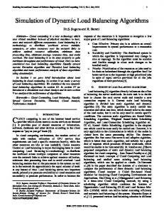
Fig. 2. From top to bottom the traffic engineering objective in the hierarchical topology hier50a, tier-1 topology with single edge failures, and tier-1 topology with SRLGs, respectively. The performance of the optimal solution and statedependent splitting is nearly identical.
B. Performance Evaluation Avoiding congestion and packet losses during planned and unplanned failures is the central goal of traffic engineering. Our traffic engineering objective measures congestion across
7
0.8
0.8
0.6
0.6 cdf
1
cdf
1
0.4
0.4 abilene wax50 tier-1 hier50a tier-1 (SRLGs)
0.2
0.2 traffic=1.0 traffic=1.8 traffic=2.6
0
0 2
3
4
5 6 7 number of paths
8
9
10
2
3
4
5 6 7 number of paths
8
9
10
Fig. 3. The number of paths used in various topologies on the left, and in the tier-1 topology with SRLGs on the right. The cumulative distribution function shows that the number of paths is almost independent of the traffic load in the network, but is larger for bigger more well-connected topologies.
all the considered failure cases. The objective as a function of the scaled-up demands is depicted in Figure 2. The results which were obtained on the hierarchical and tier-1 topologies are representative, we made similar observations for all the other topologies. In Figure 2, the performance of state-dependent splitting and the optimal solution is virtually indistinguishable in all cases. State-independent splitting is less sophisticated and does not allow custom load balancing ratios for distinct failures, and therefore its performance is worse compared to the optimum. However, the performance compares well with that of OSPF. The benefit of stateindependent splitting is that it uses the same set of diverse paths as the optimal solution. It is not surprising that the simple equal splitting algorithm achieves the worst performance. We observe that OSPF achieves a somewhat worse performance than state-independent and state-dependent splitting as the load increases. We made this observation despite the fact that we obtained a custom set of OSPF link weights for each network load we evaluated. A possible explanation is that OSPF routing, in which each router splits the load evenly between the smallest weight paths, does not allow much flexibility in choosing diverse routes and does not allow uneven splitting ratios. Solutions with few paths are preferred as they decrease the number of tunnels that have to be managed, and reduce the size of the router configuration. However, a sufficient number of paths must be available to each commodity to avoid failures and to reduce congestion. We observe that the number of paths used by our algorithms is small. We record the number of paths used by each demand, and plot the distribution in Figure 3. Not surprisingly, the number of paths is greater for larger and more diverse topologies. 92% of the demands in the hierarchical topology use 7 or fewer paths, and fewer than 10 paths are needed in the tier-1 backbone topology for almost all demands. Further, Figure 3 shows that the number of paths only increases slightly as we scale up the amount of traffic in the networks. This small increase is caused by shifting some
Algorithm Optimum State dep. splitting State indep. splitting Equal splitting OSPF (optimized) OSPF (current)
Single edge failures avg (ms) stdev 30.99 30.86 31.00 33.82 30.70 28.45
0.23 0.21 0.23 0.22 0.54 0
SRLG failures avg (ms) stdev 31.03 30.96 31.11 39.70 30.71 28.49
0.22 0.17 0.22 0.69 0.50 0
TABLE III P ROPAGATION DELAY ( AVERAGE AND STANDARD DEVIATION ) IN THE TIER -1 BACKBONE NETWORK
traffic to longer paths as the short paths become congested. Minimizing the delay experienced by the users is one of the important goals of network operators. Therefore, we calculated the average propagation delays of all the evaluated algorithms. These results, which exclude congestion delay, are summarized in Table III. We observe that the delay of OSPF with optimized link weights, state-dependent and state-independent splitting is almost identical at around 31 ms. These values would satisfy the 37 ms requirement specified in the SLAs of the tier-1 network. Moreover, we demonstrate that these values are not significantly higher than these experienced by the network users today. We repeated our simulation on the tier-1 topology using the real OSPF weights which are used by the network operator. These values are chosen to provide a tradeoff between traffic engineering and shortest delay routing, and resulted in average delays of 28.45 and 28.49 ms for the two tier-1 failure sets. In sum, we observe that the objective value of statedependent splitting very closely tracks the optimal objective. For this reason, this solution is our favorite. Although stateindependent splitting has a somewhat worse performance especially as the network load increases beyond current levels, it could be attractive due to its simplicity.
8
VI. R ELATED W ORK Most of the related work considers either failure recovery or traffic engineering alone. Traffic engineering without failure recovery in the context of MPLS is studied in [14]–[18]. [14] utilizes traffic splitting to minimize end-to-end delay and loss rates. However, an algorithm for optimal path selection is not provided. [15] and [16] minimize the maximum link utilization while satisfying the requested traffic demands. [17] and [18] avoid network congestion by adaptively balancing the load among multiple paths based on measurement and analysis of path congestion. Local and global path protection in MPLS has been a fruitful area of research. In local protection the backup path takes the shortest path that avoids the outage location from a point of local repair to the tail-end router or to the merge point with the primary path. The IETF RFC 4090 [6] focuses on defining signaling extensions to establish the backup paths, but leaves the issues of bandwidth reservation and optimal route selection open. In [1] the shortest path that avoids the failure is used, and [19] and [20] attempt to find an optimal backup paths with the goal of reducing network overbuild. While these proposals achieve certain success in reducing the network overbuild, local protection is necessarily less effective at reducing overbuild than global protection because it does not allow proper load balancing on end-to-end paths. Global path protection in MPLS allows rerouting on endto-end paths as is outlined in IETF RFC 3469 [7]. Work that describes how to manage restoration bandwidth and select optimal paths is [21], [22] and [23]. While our solution also uses global protection to reroute around failures, the biggest difference is that most of the related work distinguishes primary and backup paths and only uses a backup path when the primary path fails. In contrast, our solution balances the load across many paths even before failures occur. The only attempts to integrate failure recovery and load balancing across multiple paths either only use alternate paths when primary routes do not work [24], or they require explicit congestion feedback from the network and do not provide algorithms to find the optimal set of paths [25], [26]. Computational complexity results of the optimization problems related to failure recovery are of great interest both to the network algorithm designers and to the theory community. NPcompleteness of optimization problems with failure recovery have been studied, e.g., in [27] and [28]. VII. C ONCLUSION In this paper we propose a mechanism that combines path protection and traffic engineering to enable reliable data delivery in the presence of link failures. We formalize the problem by providing several optimization theoretic formulations that differ in the capabilities they require of the network routers. For each of the formulations, we present algorithms and heuristics that allow the network operator to find a set of optimal end-to-end paths and load balancing rules. Our extensive simulations on the IP backbone of a tier-1 ISP and on a range of synthetic topologies demonstrate the
attractive properties of our solutions. First, state-dependent splitting achieves load balancing performance close to the theoretical optimum, while state-independent splitting often offers comparable performance and a very simple setup. Second, using our solutions does not significantly increase propagation delay compared to the shortest path routing of OSPF. We are currently extending our simulations to include a range of measured traffic matrices, and to evaluate the solutions on a realistic datacenter topology. In addition to failure resilience and favorable traffic engineering properties which we demonstrate, our architecture has the potential to simplify router design and reduce operation costs for ISPs as well as operators of datacenters and enterprise networks. ACKNOWLEDGEMENT We gratefully acknowledge the support of the DARPA CORONET Program, Contract N00173-08-C-2011. The views, opinions, and/or findings contained in this article/presentation are those of the author/presenter and should not be interpreted as representing the official views or policies, either expressed or implied, of the Defense Advanced Research Projects Agency or the Department of Defense. R EFERENCES [1] J.-P. Vasseur, M. Pickavet, and P. Demeester, Network Recovery: Protection and Restoration of Optical, SONET-SDH, IP, and MPLS, pp. 397– 422. San Francisco, CA: Morgan Kaufmann Publishers Inc., 2004. [2] E. Rosen, A. Viswanathan, and R. Callon, “Multiprotocol label switching architecture,” 2001. IETF RFC 3031. [3] “JUNOS: MPLS fast reroute solutions, network operations guide,” 2007. [4] E. Osborne and A. Simha, Traffic Engineering with MPLS. Indianapolis, IN: Cisco Press, 2002. [5] I. P. Kaminow and T. L. Koch, The Optical Fiber Telecommunications IIIA. New York: Academic Press, 1997. [6] P. Pan, G. Swallow, and A. Atlas, “Fast reroute extensions to RSVP-TE for LSP tunnels,” 2005. IETF RFC 4090. [7] V. Sharma and F. Hellstrand, “Framework for multi-protocol label switching (MPLS)-based recovery,” 2003. IETF RFC 3469. [8] A. Greenberg et al., “VL2: A scalable and flexible data center network,” in Proceedings of ACM SIGCOMM, 2009. To appear. [9] D. Katz and D. Ward, “Bidirectional forwarding detection.” IETF Internet Draft, February 2009. [10] A. Markopoulou, G. Iannaccone, S. Bhattacharyya, C.-N. Chuah, Y. Ganjali, and C. Diot, “Characterization of failures in an operational IP backbone network,” IEEE/ACM Trans. Netw., vol. 16, no. 4, pp. 749– 762, 2008. [11] B. Fortz and M. Thorup, “Increasing Internet capacity using local search,” Computational Optimization and Applications, vol. 29, no. 1, pp. 13–48, 2004. [12] E. W. Zegura, “GT-ITM: Georgia Tech internetwork topology models (software),” 1996. [13] B. Fortz and M. Thorup, “Optimizing OSPF/IS-IS weights in a changing world,” IEEE Journal on Selected Areas in Communications, vol. 20, pp. 756–767, May 2002. [14] E. Dinan, D. Awduche, and B. Jabbari, “Analytical framework for dynamic traffic partitioning in MPLS networks,” in IEEE International Conference on Communications, vol. 3, pp. 1604–1608, 2000. [15] Y. Seok, Y. Lee, Y. Choi, and C. Kim, “Dynamic constrained multipath routing for MPLS networks,” in International Conference on Computer Communications and Networks, pp. 348–353, 2001. [16] Y. Lee, Y. Seok, Y. Choi, and C. Kim, “A constrained multipath traffic engineering scheme for MPLS networks,” in IEEE International Conference on Communications, vol. 4, pp. 2431–2436, 2002. [17] A. Elwalid, C. Jin, S. Low, and I. Widjaja, “MATE: MPLS adaptive traffic engineering,” in Proceedings of INFOCOM, vol. 3, pp. 1300– 1309, 2001.
9
[18] J. Wang, S. Patek, H. Wang, and J. Liebeherr, “Traffic engineering with AIMD in MPLS networks,” in IEEE International Workshop on Protocols for High Speed Networks, pp. 192–210, 2002. [19] H. Saito and M. Yoshida, “An optimal recovery LSP assignment scheme for MPLS fast reroute,” in International Telecommunication Network Strategy and Planning Symposium (Networks), pp. 229–234, 2002. [20] D. Wang and G. Li, “Efficient distributed bandwidth management for MPLS fast reroute,” IEEE/ACM Trans. Netw., vol. 16, no. 2, pp. 486– 495, 2008. [21] M. Kodialam and T. V. Lakshman, “Dynamic routing of restorable bandwidth-guaranteed tunnels using aggregated network resource usage information,” IEEE/ACM Trans. Netw., vol. 11, no. 3, pp. 399–410, 2003. [22] G. Li, D. Wang, C. Kalmanek, and R. Doverspike, “Efficient distributed restoration path selection for shared mesh restoration,” IEEE/ACM Trans. Netw., vol. 11, no. 5, pp. 761–771, 2003. [23] Y. Liu, D. Tipper, and P. Siripongwutikorn, “Approximating optimal spare capacity allocation by successive survivable routing,” IEEE/ACM Trans. Netw., vol. 13, no. 1, pp. 198–211, 2005. [24] H. Saito, Y. Miyao, and M. Yoshida, “Traffic engineering using multiple multipoint-to-point LSPs,” in Proceedings of INFOCOM, vol. 2, pp. 894–901, 2000. [25] B. A. Movsichoff, C. M. Lagoa, and H. Che, “End-to-end optimal algorithms for integrated QoS, traffic engineering, and failure recovery,” IEEE/ACM Trans. Netw., vol. 15, pp. 813–823, Nov. 2007. [26] C. M. Lagoa, H. Che, and B. A. Movsichoff, “Adaptive control algorithms for decentralized optimal traffic engineering in the Internet,” IEEE/ACM Trans. Netw., vol. 12, no. 3, pp. 415–428, 2004. [27] A. Tomaszewski, M. Pioro, and M. Zotkiewicz, “On the complexity of resilient network design,” Networks, 2009 (in press). [28] D. Coudert, P. Datta, S. Perennes, H. Rivano, and M.-E. Voge, “Shared risk resource group: Complexity and approximability issues,” Parallel Processing Letters, vol. 17, no. 2, pp. 169–184, 2007. [29] S. Fortune, J. Hopcroft, and J. Wyllie, “The directed subgraph homeomorphism problem,” Theor. Comput. Sci., vol. 10, no. 2, pp. 111–121, 1980.
A PPENDIX In this Appendix, we show that two problems are NP-hard: FAILURE S TATE D ISTINGUISHING INSTANCE : A directed graph G = (V, E), a source and destination vertices u, v ∈ V , and two sets s, s0 ⊆ E. QUESTION : Is there a simple directed path P from u to v that contains edges from one and only one of the sets s and s0 ? B OUNDED PATH L OAD BALANCING INSTANCE : A directed graph G = (V, E) with a positive rational capacity ce for each edge e ∈ E, a collection S of subsets s ⊆ E of failure states with a rational weight ws for each s ∈ S, a set of triples (ud , vd , hd ), 1 ≤ d ≤ k, corresponding to demands, where hd units of demand d need to be sent from source vertex ud ∈ V to destination vertex vd ∈ V , an integer bound J on the number of paths that can be used between any source-destination pair, a piecewiselinear increasing cost function Φ(`) mapping edge loads ` to rationals, and an overall cost bound B. QUESTION : Are there J (or fewer) paths between each sourcedestination pair such that the given demands can be partitioned between the paths in such a way that the the total cost (sum of Φ(`) over all edges and weighted failure states as described in the text) is B or less? To prove that a problem X is NP-hard, we must show that for some known NP-hard problem Y , any instance y of Y can be transformed into an instance x of X in polynomial time, with the property that the answer for y is yes if and only if
the answer for x is yes. Both our problems can be proved NPhard by transformations from the following problem, proved NP-hard by Fortune, Hopcroft, and Wyllie [29]. D ISJOINT D IRECTED PATHS INSTANCE : A directed graph G(V, E) and distinguished vertices u1 , v1 , u2 , v2 ∈ V . QUESTION : Are there directed paths P1 from u1 to v1 and P2 from u2 to v2 such that P1 and P2 are vertex-disjoint? Theorem 1: The FAILURE S TATE D ISTINGUISHING problem is NP-hard. Proof. Suppose we are given an instance G = (V, E), u1 , v1 , u2 , v2 of D ISJOINT D IRECTED PATHS. Our constructed instance of FAILURE S TATE D ISTINGUISHING consists of the graph G0 = (V, E 0 ), where E 0 = E ∪ {(v1 , u2 )}, with u = u1 , v = v2 , s = φ, and s0 = {(v1 , u2 )}. Given this choice of s and s0 , a simple directed path from u to v that distinguishes the two states must contain the edge (v1 , u2 ). We claim that such a path exists if and only if there are vertex-disjoint directed paths P1 from u1 to v1 and P2 from u2 to v2 . Suppose a distinguishing path P exists. Then it must consist of of three segments: a path P1 from u = u1 to v1 , the edge (v1 , u2 ), and then a path P2 from u2 to v = v2 . Since it is a simple path, P1 and P2 must be vertex-disjoint. Conversely, if vertex-disjoint paths P1 from u1 to v1 and P2 from u2 to v2 exist, then the path P that concatenates P1 followed by (v1 , u2 ) followed by P2 is our desired distinguishing path. � Theorem 2: The B OUNDED PATH L OAD BALANCING problem is NP-hard even if there are only two commodities (k = 2), only one path is allowed for each (J = 1), and there is only one failure state s. Proof. For this result we use the variant of D ISJOINT D IRECTED PATHS in which we ask for edge-disjoint rather than vertex-disjoint paths. The NP-hardness of this variant is easy to prove, using a construction in which each vertex x of G is replaced by a pair of new vertices inx and outx , and each edge (x, y) is replaced by the edge (outx , iny ). Suppose we are given an instance G = (V, E), u1 , v1 , u2 , v2 of the edge-disjoint variant of D ISJOINT D IRECTED PATHS. Our constructed instance of B OUNDED PATH L OAD BALANC ING is based on the same graph, with each edge e given capacity ce = 1, with the single failure state s = φ (i.e., the state with no failures), with ws = 1, and with demands represented by the triples (u1 , v1 , 1) and (u2 , v2 , 1). The cost function Φ has derivative Φ0 (`) = 1, 0 ≤ ` ≤ 1, and Φ0 (`) = |E|, ` > 1. Our target overall cost bound is B = |E|. Note that if the desired disjoint paths exist, then we can use P1 to send the required unit of traffic from u1 to v1 , and P2 to send the required unit of traffic from u2 to v2 . Since the paths are edge-disjoint, no edge will carry more than one unit of traffic, so the cost per edge used will be 1, and the total number of edges used can be at most |E|. Thus the specified cost bound B = |E| can be met. On the other hand, if no such pair of paths exist, then we must choose paths P1 and P2 that share at least one edge, which will carry two units of flow, for an overall cost of at least |E| + 1, just for that edge. Thus if
10
there is a solution with cost |E| or less, the desired disjoint paths must exist. � It is not difficult to see that adding more paths, failure states, or commodities cannot make the problem easier. Note, however, that this does not imply that the problem for the precise cost function Φ presented in the text is NP-hard. It does, however, mean that, assuming P 6= NP, any efficient algorithm for that Φ would have to exploit the particular features of that function.