If one copy of data is corrupted because of hardware, power, and/or software failures, the other copy can be used to recover the data. Note that such a .... ing system will destage some dirty blocks to the data disk and make room for the new ...... 512 MB disk partition on the second hard disk with no Linux file system partitions ...
The Design and Implementation of RAPID-Cache: A Reliable, Inexpensive, and High-Performance I/O Cache for Linux Zhiyong Xu and Yiming Hu Department of Electrical & Computer Engineering and Computer Science University of Cincinnati email: zxu,yhu � @ececs.uc.edu
Abstract
In case of a system failure, the updated data is still in NVRAM and can be recovered later. Treiber and Menon [6] pointed out that the use of NVRAM can reduce disk utilization for writes by an order of magnitude. Because of these, NVRAM plays an important role in high performance computer systems. However, the use of an NVRAM write cache introduces two problems: (1) it still has lower reliability compared to disks, and (2) it has a very high cost. Disks are impressively reliable today, with a Mean Time To Failure (MTTF) of up to 1 million hours. Such a low failure rate, coupled with possible redundancy such as RAID (Redundant Array of Independent Disks) systems used by many servers, gives a Mean Time To Data Loss (MTTDL) of several hundreds of millions of hours in a typical RAID-5 system [7]. Adding a single NVRAM write cache in front of a disk system creates a reliability mismatch and a single point of failure, which is vulnerable to data loss. Savage and Wilkes pointed out in [7] that because typical NVRAM technology (battery backed RAM) has a quite low MTTF of 15K hours. A single-copy NVRAM cache suffers significantly higher risk of data loss than results from disk failures. To overcome the reliability problem, it is possible to use dual-copy caches so that a failure in one cache leaves the other cache intact [8]. When a write request comes, the controller writes two copies of the data independently into the two caches, a primary cache and a backup cache. Besides the reliability problem, NVRAM is also known to be very costly [7, 9] so the size of the NVRAM cache is often limited. For example, a major NVRAM manufacturer quoted the of NVRAM with embedded lithium-cell batteries for ������price � MB in quantity recently. The cost of disks, on the other hand, is about 0.1 cents/MB, which is a difference of four orders of magnitude. Moreover, the cost difference is widening (the difference was three orders of magnitudes two years ago), because prices of disks are falling very rapidly. For a system with a reasonably sized write cache (say 128 MB or more), the cost of NVRAM is much higher than those of disks, and will dominate the cost of the entire system. If we use dual-copy caches to ease the reliability problem of the single-copy cache, the cost becomes prohibitively high, particularly for large caches.
Most file system performance enhancing techniques, such as the I/O buffer cache and the Log-structured File Systems (LFS), relying on caching data in volatile RAM for a period of time before destaging them to disk. Such approaches pose a reliability problem. Non-volatile RAM (NVRAM) caches can be used to enhance the reliability. However, large NVRAM caches are very expensive and not as reliable as disks. This paper presents the design and implementation of a different approach called RAPID-Cache (Redundant, Asymmetrically Parallel and Inexpensive Disk Cache) for highly-reliable systems. The new approach provides an inexpensive way to make the OS buffer cache non-volatile and highly reliable. Recent researches using simulation suggest that as a cache inside a disk array controller, RAPID-Cache has great reliability/cost advantages over conventional write cache structures. In order to validate whether RAPID-Cache can really achieve satisfactory performance in real systems, and to see if RAPID-Cache can also improve the performance/reliability of the OS buffer cache, we have designed and implemented RAPID-Cache for the Linux system. Measurement results using realistic benchmarks show very promising results. Using only 3.25 MB of NVRAM, a RAPID-Cache outperforms normal NVRAM caches of 64 MB or even 128 MB. RAPID-Cache also provide better reliability than normal NVRAM caches.
1 Introduction Disk I/Os are a major performance bottleneck for many applications. Many solutions have been proposed to improve disk I/O performance, such as the file system buffer cache used in most modern OSs, the Log-structured File Systems (LFS) [1], Metadata Logging [2], Soft Updates [3] and Disk Caching Disks (DCD) [4]. Most of these techniques keep some dirty data in RAM for a period of time before destaging them to disk. For example, in most Unix systems, dirty data are left in the buffer cache for 30–60 seconds before they are written to disk. Such a delay between updating data in RAM and committing them to disk poses a potential reliability problem. Some servers use non-volatile RAM (NVRAM) to improve both performance and reliability. NVRAM is normally used as a write cache to reduce the I/O response time seen by users [5, 6].
1.1 RAPID-Caches The standard dual-copy write cache system has a symmetric structure, where both the primary write cache and the backup
1
RAPID-Cache into the OS buffer cache, it is not clear how write cache have the same size and the same access characterthe architecture will interact with other kernel components. istics — fast read speed and fast write speed. However, the backup cache does not provide any performance benefit to the 2. What is the real performance of RAPID-Caches in a real syssystem during normal operations. Therefore it is wasteful to use tem? a backup cache identical to the primary cache. What is needed is The performance results (I/O response times and throughput) only a backup cache that can be written to very quickly while its in the original studies of RAPID-Caches were obtained using read operations are not as critical, since reads from the backup simulation only. However, [13] have shown that I/O response cache occur only during error-recovering periods. times are not always a good performance indicator in I/O sysBased on these observation, Hu and Yang proposed a new tems because not all I/O requests affect the system behavior disk cache architecture: Redundant Asymmetrically Parallel and in the same way. Trace-driven simulations also have limited Inexpensive Disk Cache or RAPID-Cache for short [10, 11]. It accuracy because there is no feedback between the traces and uses an asymmetric structure: a conventional, fast-write-fastthe simulators. The main objective of this research is to examread cache as a primary cache and a non-volatile, fast-writeine whether RAPID-Cache will really have good performance slow-read cache as a backup cache. The primary cache is made in the real world. We believe that the best way to evaluate the of normal NVRAM or DRAM, while the backup cache consists real world performance is to actually implement the RAPIDof a small NVRAM cache and a cache disk (or disk partition). Cache architecture and measure its performance in terms of In the backup cache, small and random writes are first buffered program execution times, using some realistic benchmarks. in NVRAM, then they are assembled into some large logs and written to the cache disk later, which is similar to Log-Structured The paper is organized as follows. Section 2 presents the File systems [1, 12]. This two-level backup cache appears as a overview of RAPID -Cache, Section 3 gives detailed descriplarge NVRAM and can achieve nearly the same write speed as tion of data structures used in RAPID-Cache implementation. the primary cache. The slow read speed of the cache disk is not a In Section 4, we describe the operations in RAPID-Cache. Secconcern since normal read requests go to the primary cache. Us- tion 5 includes performance testing results. We discuss related ing RAPID-Cache, we can get a system with higher reliability work in Section 6 and conclude the paper in Section 7. compared to one-copy write buffer, and a lower cost compared to dual-copy write buffer.
2 Redundant Asymmetrically Par1.2 Using RAPID-Caches to Improve OS allel and Inexpensive Disk Cache Buffer Cache Performance and Relia(RAPID) bility
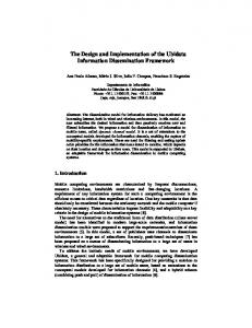
Figure 1 shows the general structure of RAPID-Cache. It consists of a conventional primary RAM cache and a backup cache. The backup cache is a two-level hierarchy with a small NVRAM on top of a cache disk, similar to DCD [4].
In [10, 11], trace-driven simulation experiments show that RAPID-Caches are very effective as write caches of large RAID systems. We try to apply the same idea to a different system component: the Unix I/O buffer cache. The basic idea is to use a reliable, inexpensive, fast-write-slow-read backup cache (consists of a small NVRAM buffer and a cache disk) to supplement the regular RAM-based I/O buffer cache (which acts as the primary cache). During normal operations, the system writes two copies of the same data, one to the buffer cache (primary), the other to the backup cache. Most data blocks in the backup cache are kept in the cache disk, which is more reliable than NVRAM. If one copy of data is corrupted because of hardware, power, and/or software failures, the other copy can be used to recover the data. Note that such a configuration is particularly resilient to data corruption caused by buggy software. “Wild-writes” caused by buggy software can easily cause random data corruption in RAM. On the other hand, to access data on disk and in most NVRAM systems, a well-defined sequence of actions must be followed. It is unlikely that run-away bugs will following such sequences. This paper tries to address the following two questions:
Incoming Requests
File System
DRAM Primary Cache
NVRAM Backup Write Cache
(Buffer Cache)
Data Disk
Cache Disk
Figure 1: The Structure of RAPID-Cache
1. Is the RAPID-Cache architecture suitable for the OS I/O buffer cache? The original RAPID-Cache architecture was designed for I/O caches of large RAID systems. It takes I/O requests after they are filtered by the OS buffer cache. When integrating the
In RAPID-Cache, the primary cache and the backup cache have identical content. If one of these two caches fails, the data can be reconstructed from the other. Because the backup cache is
2
The overhead is much less than in LFS (LFS needs to read several segments from disk). In addition to the low-cost garbage collection algorithm, in actual experiments, we found that for the workload we used, the RAPID-Cache almost never had to call the garbage collector, meaning that the garbage collection overhead has virtually no impact on the overall system performance. This is due to the following two reasons. First, because disk spaces are so inexpensive now ( about 0.1 cents per MB as of this writing), we normally choose a cache space that is 5–10 times larger than the primary write cache size. For example, for a primary buffer cache size of 128 MB, we can use a disk space of 512 MB as the cache space. Since the 128 MB of data are spread over a space of 512 MB, much of the disk space is empty (or invalid) therefore does not need garbage collection. Second, unlike an LFS system which writes both actively-accessed data and inactive data into a segment, in a RAPID-Cache system, active data and inactive data are separated. Most active data are kept in the LRU cache, while data in the disk segments of the cache-disk are relatively inactive. Therefore entire segments are often invalidated because the background destage threads constantly destage inactive data to disk. As a result, most of time the system can find an empty disk segment without the need for garbage collection.
composed of NVRAM and a cache disk, both of them are nonvolatile, all dirty data in primary cache have copies in backup cache. In case of system crashes, no data loss occurs. Although disk access speed is much slower compared to DRAM and NVRAM, the two layered structure of backup cache integrates several small writes into one big disk write, which greatly reduces seeking and rotation time. So these additional disk writes to cache disk will not degrade system performance too much. RAPID-Cache does need a cache disk, which may incur an additional cost. However, the cache disk size can be small, since the amount of valid data in the entire backup system is the same as those in the primary cache. We find that to achieve good performance, the cache disk size should be around 4–5 times of the primary cache size. For example, if the primary buffer cache size is 128MB, then a cache disk of 512 MB is sufficient. Larger disk is not necessary, while too smaller a disk may cause too much garbage collection traffic (to be discussed shortly). As of this writing, an EIDE disk of 30 GB has a retail price of about $50, which is fairly inexpensive comparing to that of NVRAM ($50/MB). Moreover, since we need only 512 MB (less than 2% of the total 30 GB capacity) of space to cache data, the remaining space can be used to store other files, as long as these files are not accessed too frequently to cause much increased traffic to the disk. To reduce cost, in a multi-disk system, instead of buying a new disk, we can also choose a less-busy disk and create a cache disk partition on it.
2.4 System Recovery If one copy of data is corrupted because of hardware and/or software failures, the other copy can be used to recover the data. In case of power failure, dirty data in the primary cache (RAM) will be lost. The backup cache will be used to recover the data after reboot.
2.1 Writes In RAPID-Cache, when a write request comes, the system sends the data to both the primary cache and the backup cache. In the primary cache, if there’s no more space available, the operating system will destage some dirty blocks to the data disk and make room for the new coming data. Meanwhile, the copy of the destaged data in the backup cache is also invalidated.
3 Design and Implementation In this section, we describe the design and implementation of RAPID-Cache for Linux. The experimental system is built on Redhat Linux 7.2 with an upgraded 2.4.12 kernel. The RAPIDCache implementation is integrated into the kernel with moderate modification to the file system source code. In the modified kernel, each dirty block has copies in both the system buffer cache and the RAPID-Cache backup cache. Linux makes intensive use of the buffer cache to reduce the overhead of slow disk I/Os. Each block in the buffer cache corresponds to one data block on disk and has a buffer head storing its description. The kernel manages these blocks by buffer heads. Each buffer must stay in one of the following lists: Unused Buffer List, Locked Buffer List, Uptodate Buffer List or Dirty Buffer List. Dirty Buffer List maintains all dirty blocks before the modifications arrive the data disk [15, 16, 17] and form the primary write cache. RAPID-Cache replicates all these dirty blocks in the backup cache and eliminates the possibility of information loss. Figure 2 shows the general structure of the RAPID backup cache. It includes three main parts: a small size of NVRAM, a small portion of system memory and a cache disk or a disk partition. Data structures in NVRAM include (1) a LRU Cache which backups the most recently written data blocks, (2) two Segment Buffers which buffer several data blocks before writing them to
2.2 Reads Read is straightforward in RAPID-Cache. All read requests are sent to the primary cache, just as the cases in a regular system. The backup cache is not involved in read operations except in crash recovery.
2.3 Garbage Collection Log-based storage solutions, such as LFS or DCD, have to perform garbage collection or data destage from time to time in order to free the log space. Garbage collection or destaging process can significantly reduce the overall system performance when the workload is high. RAPID-Cache also needs garbage collection to free up cache disk space. However, the operation itself is much easier than in LFS. Since all data on the cache disk have a copy in the primary cache, to do garbage collection, the RAPID Cache simply chooses several fragment segments, copies the corresponding data from the primary cache to a segment buffer and write it to the cache disk, and invalidate all these fragment segments. Only one segment write is invoked and no disk read is needed.
3
In−memory data structures
LRU cache
Segment table
Segment buffer
Data lookup table
Head
Rapid LRU list
RAM buffers Segment buffer
Disk Segment 0
RAM
NVRAM
LRU cache table
Disk Segment 1
Disk Segment 2
Slot 1 Slot 2 Slot 3
Disk Segment 3
...
...
Slot 31
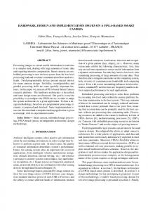
Figure 3: The Cache Disk Organization
Free rapid cache head list
3.2 NVRAM data structures
Cache disk (Disk partition)
3.2.1 LRU Cache Figure 2: The Detailed Illustration of RAPID-Cache Backup Cache
The LRU cache is the higher level of RAPID backup cache. It stores copies of the most recently written data in the primary buffer cache. When a block in the primary cache is modified and inserted into the Dirty Buffer List, this block is also sent to the backup cache. RAPID-Cache adds it to the LRU cache. If the LRU cache is full and has no place for this new block, several least recently used are destaged from LRU Cache to one segment buffer to make room for the incoming request. In case that block is already in the backup cache, the old copy will be invalidated. The detailed operation is given in Section 4. The LRU cache is divided into many 4 KB slots. For a 2 MB LRU cache, the number of slots is 512. Each slot can store one data block. The description information of a valid block in LRU cache is stored in a Rapid cache head and each block has entries in both the Data Lookup Table and the Rapid LRU List. These data structures will be discussed shortly. The entry in Data Lookup Table speeds up searching for blocks. The entry in the Rapid LRU List is to keep the access order of all blocks in the LRU cache. These two lists have different coverage. Any valid data block in the backup cache, no matter in the LRU cache, a segment buffer or on the cache disk, has an entry in the Data Lookup Table. But only valid blocks in LRU cache have entries in the Rapid LRU List.
the cache disk, (3) a Segment Table maintaining the usage information of segment buffers and all cache disk segments, and (4) a LRU Cache Table storing information of all valid blocks in the LRU Cache. These are the most important data structures and must be kept in NVRAM. In case of a crash, they are used to rebuild data. Data structures in the system memory include (1) a Rapid LRU List which is a doubly-linked list connecting all blocks in the LRU Cache, (2) a Free Rapid Cache Head List maintaining all the free rapid cache heads, and (3) a Data Lookup Table. Our design is sightly different from the original RAPID-Cache in utilizing system memory management for data lookup table. These reason is that the lookup table is accessed very frequently therefore its performance is important. For the NVRAM card we used, its access speed is slower than that of system DRAM because each access has to go to the PCI bus. The table content can be rebuilt after a crash from data on the cache disk and in the NVRAM.
3.1 Cache Disk Organization
Slot 0
The cache disk is the lower level storage device of RAPIDCache, only the relatively inactive data blocks evicted from the LRU cache are stored on it. Figure 3 shows the structure of the cache disk. It is divided into several large, fixed-length segments, similar to the cases in LFS and DCD. Each segment contains a segment head followed by a fixed number of slots (4 KB each), which is the same as described in segment buffers. The segment size in our implementation is 128 KB, which is the maximum I/O size in Linux. The 128 KB segment contains a segment head and 31 slots. A segment is the basic unit for disk I/O in RAPID-Cache. The RAPID backup cache reduces disk I/O overhead by converting many small disk writes into several large segments I/Os, therefore significantly reduce time spent on disk seeking and rotation.
Slot 1
Slot 511
Figure 4: The Structure of a 2MB LRU Cache
3.2.2 Segment Buffers Because the LRU cache is small, when it fills up, less active data are evicted and moved to the cache disk. Since a segment is the basic unit for disk I/O, data blocks evicted from the LRU cache are first assembled in one of the two segment buffers. When the buffer is full, the entire buffer is written in to an empty disk segment on the cache disk in a single large disk write. Since large I/O are very efficient, the write speed is very high. The segment buffers in NVRAM and the disk segments on cache disk have the same structure. The structure of a segment buffer is shown in Figure 5. It can be divided into two parts: Segment Head: It stores information of all data blocks within this segment buffer. Its size is 2 KB and it contains the
4
Segment Head
Slot 1
...
Slot 2
3.2.4 Segment Table
Slot 31
The segment table records the current usage of all segment buffers in NVRAM and disk segments on the cache disk. Figure 7 shows segment table structure. Each entry in the table has the following fields:
Segment_ID Segment_Size Valid_Slot_Num Time_Stamp
valid slot num: The number of valid slots in the segment (segment buffer or disk segment). The size is 4 bytes.
Slot 0 LBA Slot 1 LBA
slot LBA table: It has the same meaning as slot LBA table in a segment head. The size is 31 (4+4) = 248 bytes.
Slot_Map
�
Slot LBA Table
valid slot bitmap: This field describes which slots in this segment contain valid data blocks. It needs 31 bits for all slots. We use 4 bytes.
Slot 31 LBA
Figure 5: The Structure of a Segment
ptr table: It stores the pointers to both buffer head and rapid cache head of valid blocks in this segment. It has 31 entries. This table is used in garbage collection and the size is 248 bytes. Since the contents of this table can be rebuilt from other data structures after a crash, in our implementation this table is actually stored in DRAM, thus it does not take precious NVRAM space.
following fields: A segment ID, which uniquely identifies the segment. The segment ID of a disk segment is determined by its distance from the start of cache disk. A segment size, which is set to 128 KB in our implementation.
Segment Buffer 0 entry
A valid slot num indicates the number of slots which contain valid data block in this segment. The largest value is 31 which means all data blocks are valid. When valid slot num reaches 0, the segment contains no valid block and can be freed and reused.
Segment Buffer 1 entry
Valid_slot_num Valid bit 0 Valid bit 1
Disk Segment 1 entry Disk Segment 2 entry Valid bit 31
slot_LBA_table
A time stamp, which records system time when this segment is created.
ptr_table Disk Segment n entry
A slot map indicates which slot contains valid block.
ptr_table
A slot LBA table indicates the corresponding location of all data blocks on the data disk. It has 31 entries with each slot having one entry. Each entry in this table records the LBA of a block and is used as a search key in data lookup table.
bh_ptr
bh_ptr
rch_ptr
rch_ptr
Figure 7: The Structure of Segment Table
Slots: Slot is the basic allocation unit in a segment and it contains a data block identified by a rapid cache head. A cache disk of 512 MB contains 4096 segments, plus two segment buffers in NVRAM. So the segment table has 4098 entries, each entry needs 4+4+248 = 256 bytes. The total size of segment table is 4098 256 = 1 MB. The Segment table along with the LRU cache table can identify all valid data blocks in the backup cache.
3.2.3 LRU Cache Table LRU Cache Table is used to store information of all valid blocks in the LRU Cache. Since the block size is 4 KB, for a 2 MB LRU Cache, it contains 512 entries, each entry records rch dev and rch blocknr of a block. It needs 512 (4+4)=4 KB of storage space. And another 512 bits are used as a valid bit map.
�
�
rch_dev rch_blocknr valid_bit 0
3.3 RAM data structures 3.3.1 Rapid Cache Head
rch_dev rch_blocknr valid bit 511
Rapid cache head is the basic data structure in RAPID-Cache. Like a buffer head is used to identify a block in buffer cache, a rapid cache head uniquely identifies a valid block in the backup cache. Because each block in the backup cache is a replica of a dirty block in the primary cache, each rapid cache head corresponds to one buffer head in the primary buffer cache, and can identify one data block with maximum size of 4KB. It has similar structure as a buffer head. Figure 8 shows the organization of a rapid cache head. Detailed fields descriptions are:
Figure 6: The Structure of the LRU Cache Table
5
Rapid cache head
slot id: the slot ID of a block. No matter the block is in LRU cache, segment buffer or cache disk, the value is the slot id which contains this block.
rch_dev rch_blocknr rch_size
Using seg id and slot id, RAPID-Cache can uniquely identify the location of a block. During system recovery, the data block can be read from the backup cache and written back to its corresponding location in the primary cache and on the data disk.
rch_prev rch_next rch_lru_prev rch_lru_next rch_state seg_id slot_id
data block
3.3.2 Data Lookup Table One of the most challenging tasks in RAPID-Cache implementation is to design an efficient data structure and a searching algorithm for the data lookup table, which is used to locate data blocks in the backup cache. Each time when a block is inserted into the primary buffer cache, or a block in the primary cache is modified, RAPID-Cache must search the table to locate this block in the backup cache before adding it into the LRU cache. The data structures and searching algorithms must be simple and fast to reduce overhead. While the Segment table along with the LRU cache table in NVRAM can identify all valid data blocks in the backup cache, they are not optimized for searching using block IDs. Moreover, compared to DRAM, NVRAM is expensive, and slower to access (because for PCI-based NVRAM cards, each memory access has to go to the slow PCI bus). To solve this problem, an index called Data Lookup Table is created in RAM. The table can be re-constructed from data in NVRAM after a crash. Each rapid cache head has an entry in the table, no matter it is in the LRU cache, in one of the segment buffers or on the cache disk. Like the buffer head uses device number and block number to address a block, we use rch dev and rch blocknr (LBA) as the search key for a rapid cache head in the data lookup table. Similar hash table and searching algorithms used in Linux are adopted here. Rapid cache heads which are mapped to the same hash value in data lookup table generate a doubly-linked hash list, which is connected through rch hash prev and rch hash next. The detailed structure of the data lookup table is shown in Figure 9. Each time when a new block is added into the backup cache, RAPID-Cache locates the corresponding doubly-linked hash list according to its LBA value. Then this hash list will be searched from the head. If an entry’s LBA matches this new coming data block, it is a cache hit which means this new block is an updated version of a data block that already exists in the backup cache. This data block can be in the LRU cache, a segment buffer or on the cache disk, different operations will be done according to different situations. The detail is presented in Section 4. If RAPID-Cache reaches the last entry of this hash list and cannot find this block (a cache miss), it means this data block is added to the backup cache for the first time. We insert it to the LRU cache, and create entries for it in the data lookup table and the Rapid LRU list. In both cases, we add it to the head of the list.
Figure 8: The Structure of a Rapid Cache Head
rch dev: the real disk device number of the block. It is the same as b rdev in the corresponding buffer head in the primary write cache. rch blocknr: the real block number of the block on rch dev, same as b blocknr in the corresponding buffer head. The Logical Block Address (LBA) of a block in the backup cache is composed of rch dev and rch blocknr. It is used to locate a block in the Data Lookup Table. rch size: the size of a block. It must be multiples of disk sector size (512 bytes). The maximum size is 4 KB. rch prev and rch next: pointers to the previous and next entries in one hash list in Data Lookup Table. A double linked list with the same hash value is connected by these fields. rch lru prev and rch lru next: pointers to the previous and next entries in Rapid LRU list, if a block has been moved to a segment buffer or cache disk, these two fields are set to NULL. All rapid cache heads which point to blocks in the LRU cache are put in the RAPID LRU List. Each time when a new block is inserted into the backup cache, we add it to the LRU cache first, and put its rapid cache head to the head of the Rapid LRU List. In case that the LRU cache is full, we only flush the data blocks in the tail of the Rapid LRU List from the LRU cache to a segment buffer. When the buffer fills up, the entire is written to the cache disk in a single I/O. By this way, we can keep the most active data blocks in the LRU cache. rch state: A block in the backup cache can be in one of the three places at any give moment. This field is used to indicate the state of the block. It can have one of three different values: RCH LRUCACHE indicates the block is in the LRU cache; RCH LOCK indicates the block is in one of the segment buffers and is locked for destaging to the cache disk; RCH DISK indicates that the block has already been destaged to the cache disk. The address of the block is stored in the following two fields: seg id: the segment ID of a block. If the block is in the LRU cache, the value is set to -1. If it is in a segment buffer, the value is set to 0 or 1 (depend on which buffer it is located). If it is already on cache disk, the value is the corresponding disk segment ID.
6
Hash Table 0 1
block
2
block
block
as shown in Figure 10(b). When the write finishes and the rch state is changed to RCH DISK , the following operations are the same as described next.
block
3. rch state is RCH DISK, which means that the block is on the cache disk. In this case, we do not modify the segment head information of that disk segment in order to avoid the high overhead of disk accesses. We only modify the corresponding entry in the segment table: decrease valid slot num of that disk segment by 1, set the corresponding slot bit to 0 to indiblock block N−1 cate that the data block in this slot is invalid now. Then the hash value new data block is added to the LRU cache, the rch state is set to RCH LRUCACHE again. Other fields such as seg id and Figure 9: The Structure of Data Lookup Table slot id are reset accordingly. The corresponding rapid cache head is added to the heads of both the hash list in data lookup table and rapid LRU list which are the same operations as a). Also, the LRU cache table is modified to reflect this change. 3.3.3 Rapid LRU List and Free Rapid Cache Head The whole process is shown in Figure 10(c). List A Rapid LRU List contains rapid cache heads of all valid data blocks in the LRU Cache. Rapid LRU List Head and Rapid LRU List Tail point to the start and the end of Rapid LRU List. All unused rapid cache heads form another list – Free Rapid Cache Head List. Every time when a new data block is sent to the backup cache, RAPID-Cache allocates a free rapid cache head for it. Every time a data block is invalidated, its rapid cache head is freed and added to the Free Rapid Cache Head List again.
Rapid LRU List Tail Rapid LRU List Head
Rapid LRU List Tail
Rapid LRU List Head
old
new
LRU cache
LRU cache
new
a). rch_state is RCH_LRUCACHE
new
Rapid cache head
new
Rapid cache head
old
4 Operation Details
b). rch_state is RCH_LOCK
In this section, we describe operations in RAPID-Cache, which include write, read, garbage collection and crash recovery.
Rapid LRU List Tail new
4.1 Writes
Rapid LRU List Head new
Rapid cache head
LRU cache
old
Cache Disk
When a write request comes, the modified data block is sent to both the buffer cache (primary) and the backup cache. We did not modify original Linux operations on the primary buffer cache. RAPID-Cache is responsible for operations in the backup cache. First, the hash value of this data block’s LBA is calculated, then the corresponding hash list in the data lookup table is selected. If the hash list is not empty, RAPID-Cache starts searching from the head and stops when a rapid cache head with the same LBA is found (a cache hit). In this case, RAPID-Cache knows that the newly coming data block is an update to a block that already exists in the backup cache. The next operation is to check the location of this block in backup cache. It is done by checking rch state field which must have one of the following three values:
Cache Disk c). rch_state is RCH_DISK
Figure 10: Three Write Operations in RAPID Backup Cache (Cache Hit) If we cannot find a rapid cache head in the data lookup table matching this LBA, we know it is a newly coming data block. Then it must be added into the backup cache. First, an unused rapid cache head is taken from Free Rapid Cache Head List, and fields in this rapid cache head are filled according to the information in the buffer head. Second, RAPID-Cache adds this block into the LRU Cache:
1. rch state is RCH LRUCACHE, which means that the data 1. If the LRU cache still has free space, the content of the block block is still in the LRU Cache. We simply overwrite its conis copied into the LRU cache and its address in the cache is tent in the LRU Cache, move the corresponding rapid cache saved in seg id and slot id. Its rapid cache head is added to head to the heads of both the hash list in the data lookup table the heads of both the hash list in the data lookup table and the and the rapid LRU list (which means it is the most recently rapid LRU list. The LRU cache table is modified accordingly. accessed data). The operations are shown in Figure 10(a). 2. In case that the LRU cache is full, RAPID-Cache picks an 2. rch state is RCH LOCK, which means that the block is empty segment buffer, sets it the “current” segment buffer and locked in one of the segment buffers for destaging to the cache copies contents of the last 31 data blocks in the rapid LRU list disk. We must wait for the completion of this disk write, from the LRU cache to this segment buffer. The entries in
7
4.3 Garbage Collection
both LRU cache table and segment table are modified. Since segment buffers are also located in NVRAM, space used by those blocks in LRU cache are safely freed, and the newly coming data block is inserted into the LRU cache. Also its rapid cache head is added to the heads of both the hash list in the data lookup table and the rapid LRU list. And its entry in the LRU cache table is set. Now RAPID-Cache schedules one large write to copy the entire contents of the current segment buffer to an empty disk segment on the cache disk. RAPIDCache switches to another empty segment buffer as current segment buffer. Since the entire contents is written to cache disk in one large write instead of many small writes, the segment buffer is available again quickly after the write finishes.
If the percentage of used segments on the cache disk reaches a threshold, for example, 70%, RAPID-Cache will start a garbage collection operation. First, the segment table is searched and disk segments which have few valid blocks (fragmented segments) are selected. Second, using ptr table in the segment table, the valid data blocks in these fragmented segments are copied from the primary cache to a segment buffer. Third, when this segment buffer is full, a large disk write is scheduled to destage its contents to the cache disk. After write finishes, the data lookup table and the segment table are modified accordingly. The fragmented disk segments are freed and can be reused. As discussed before, in real systems, garbage collection almost never happens, so it basically has no performance impact. We use a 512 MB cache disk in our experiments and found most segments in cache disk are made empty (its valid slot num in the segment table reaches 0) quickly. It hardly happens that 70% of the cache disk are used, so there’s no need to perform garbage collection at all.
When a block in the primary cache is destaged to the data disk, the corresponding block in the backup cache needs to be invalidated. If this block is in the LRU Cache, the slot occupied by this block is freed and the entry in LRU cache table is set to NULL. If it is in a segment buffer, the valid slot num is decreased by 1 and the corresponding entry in the slot map is marked as invalid; if it is on the cache disk, RAPID-Cache will not modify the corresponding disk segment head on the cache disk (otherwise the overhead will be too high), but simply modifies its in-memory copy in the segment table. In all cases, the rapid cache head of this block is freed and added to the Free Rapid Cache Head List. Rapid LRU List Tail Rapid LRU List Head
4.4 Crash Recovery Crash recovery in RAPID-Cache can be divided into two categories:
Rapid LRU List Tail Rapid LRU List Head
4.4.1 System Crash
new
LRU cache new
If the entire system crashes, the modified data can be safely recovered during system reboot time. We set a crash flag in the system boot sector. During system booting time, RAPID-Cache sets this flag. If the system shutdown correctly, this flag will be cleared. When the system starts, RAPID-Cache checks this flag and starts the crash recovery process if the flag is set. The process is strait-forward. Before any new disk I/O is issued to the data disk, the LRU cache table and segment table are searched, all valid data in the backup LRU Cache, segment buffers and the cache disk are copied back to the data disk. Then all components in the RAPID backup cache are initiated.
LRU cache a). LRU Cache is not full
Rapid LRU List Tail Rapid LRU List Head
Rapid LRU List TailRapid LRU List Head new
LRU cache
LRU cache new
Current Segment Buffer
Current Segment Buffer
b). LRU Cache is full
4.4.2 Cache Crash Figure 11: Write Operations in RAPID backup cache (Cache Miss)
In case that the primary buffer cache is corrupted, each dirty block in it have a copy in backup cache and can be recovered. In case that RAPID backup cache has problems, for example, the NVRAM or cache disk fails, we can perform a regular system shutdown, which cause data in the primary cache be safely written to the data disk. We then replace the failed component and reboot. If the system supports hot-swappable disks/NVRAM, we can replace the failed device while system keeps running. Then all dirty data blocks in the primary cache are copied to the backup cache.
In summary, in write operations, the backup cache (the small NVRAM together with the cache disk) functions like a large NVRAM write cache and can achieve similar performance and better reliability.
4.2 Reads The backup cache does not participate in normal read operations. Just like in a regular file system, the Linux system simply searches the requested block in the primary buffer cache, and gets the data from the cache on a cache hit, or fetches the data from the data disk on a cache miss.
8
5 Performance Evaluation
512 MB disk partition on the second hard disk with no Linux file system partitions on it. In this configuration, all file systems are mounted using synchronous mode.
5.1 Benchmarks and Experiment Environment
We reboot the system before executing a experiment every time, thus the benchmarks are running with a cold cache effect.
We created a set of benchmarks similar to the ones used by Nightingale et al. in [18]. The benchmarks consist of three sets of programs: N-user untar, N-user copy and N-user delete. Nuser untar simulates one or more users concurrently ] and independently decompressing and un-taring a tar.gz file to create a directory tree. N-user copy and N-user delete simulate one or more users concurrently copying or deleting the entire directory tree created by N-user untar, respectively. We also choose the PostMark disk I/O benchmark [19] to test disk I/O bandwidth. These benchmarks represent typical and realistic I/O intensive tasks performed by normal users on a daily basis. The particular .tar.gz files we used are the source code distribution tar files of emacs-20.7 and Linux kernel 2.4.12. Emacs is one of the most popular editors in the UNIX environment. The resulting source file tree contains 33 sub-directories and 2051 files with an average file size of 27.45 KB. The total size of the directory tree is 56.3 MB. For Linux kernel 2.4.12, the resulting source file tree contains 501 sub-directories and 9679 files with an average file size of 11.87 KB. The total size of the directory is 112.2 MB. All experiments were conducted on an Intel Pentium 4 1.8 GHz PC, running Redhat Linux 7.2 with an upgraded 2.4.12 kernel. Standard EXT2 file system is used. The machine has 256 MB memory, two IBM Deskstar 20 GB 7200RPM Ultra ATA/100 drives with an average seek time of 8.5 ms. An MM5415CN NVRAM PCI card from Micro Memory Inc. was used. All the Linux file systems are located on the first hard disk. We ran benchmarks on the following different system configurations:
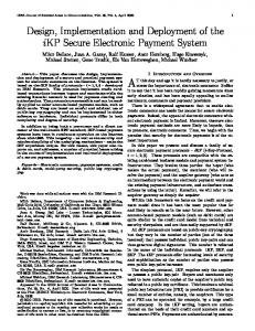
5.2 Execution Time 25
Baseline (Sync) Baseline (Async) NVRAM (4MB) NVRAM (16MB) NVRAM (64MB) NVRAM (120MB) RAPID (3.25MB)
20
15
10
5
0 1-user untar
1-user copy
1-user delete
Figure 12: Benchmark Execution Time for 1-user untar, copy and delete of Emacs
90
Baseline (Sync) Baseline (Async) NVRAM (4MB) NVRAM (16MB) NVRAM (64MB) NVRAM (120MB) RAPID (3.25MB)
Program Execution Time (Seconds)
80
1. Baseline (Sync): We used Redhat Linux 7.2 with an unmodified kernel 2.4.12 as a baseline system. In this configuration, Linux file systems are mounted in the synchronous mode. Since file data are cached in the buffer cache, it will cause data loss in case of power failures or system crashes.
70 60 50 40 30 20 10 0 1-user untar
2. Baseline (Async): This configuration is the same as Baseline (Sync) except that all Linux file systems are mounted in the asynchronous mode. It has better performance than Baseline (Sync). However, since meta-data updates are asynchronous, it does not guarantee file system consistence after crash, and is not suitable for most applications.
1-user copy
1-user delete
Figure 13: Benchmark Execution Time for 1-user untar, copy and delete of Linux Kernel
We measured the performance of these configurations in terms of execution time. Both 1-user and 4-user operations are tested, the results are shown in Figures 12, 13 and 14. We used the Unix time command to measure benchmark execution times, the user time and system CPU time. All numerical results shown here are the average of three runs. For the two baseline systems, the results show that Baseline (Sync) has the worst performance in all cases, because of the high cost of synchronous meta-data updates. Baseline (Async) in general has the best performance (except that in 1-user untar of Linux). However it does not guarantee file system consistence therefore is not suitable for most applications. Using NVRAM as write caches can improve both performance and reliability. When the cache size is small (4 MB),
3. NVRAM: We used NVRAM as a regular second level buffer cache. The NVRAM sizes used are 4 MB, 16 MB, 64 MB and 128 MB. Each time when a write request comes in, no matter it is a synchronous or asynchronous write, we write it to the NVRAM. A write complete signal is then sent back to the system. If the NVRAM is full, we choose several LRU dirty blocks and write them back to disk using synchronous writes. This NVRAM functions as a big non-volatile buffer cache. In this configuration, all file systems are mounted using synchronous mode. 4. RAPID: The backup cache uses 3.25 MB of NVRAM (2 MB for the LRU Cache, 1 MB for Segment Table, and two 128 KB segment buffers) unless otherwise noted. The cache disk is a
9
70
300
Program Execution Time (Seconds)
250
200
Program Execution Time(Seconds)
Baseline (Sync) Baseline (Async) NVRAM (4MB) NVRAM (16MB) NVRAM (64MB) NVRAM (120MB) RAPID (3.25MB)
150
100
50
50 40 30 20 10 0 256K
0 4-user untar
4-user copy
Baseline(Sync) Baseline(Async) RAPID
60
512K 768KB 1024K
2048K
4096K
8192KB
LRU cache size
4-user delete
Figure 15: Impacts of RAPID LRU caches on 1-user untar of Linux
Figure 14: Benchmark Execution Time for 4-user untar, copy and delete of Emacs
NVRAM (4MB) performs slightly better than Baseline (Sync), and the reliability is improved also since dirty data are cached in NVRAM instead of RAM. As the cache sizes increases to up to 120 MB, the performance gain noticeably improves also. RAPID-Cache has the best performance/reliability combination among all systems. Only Baseline (Async) is slightly faster than RAPID (3.25MB), because the latter has to perform much more work (keeping two copies of data) in order to provide much better reliability. In fact, with only 3.25 MB of NVRAM, RAPID (3.25MB) outperforms NVRAM (120MB) in all but three cases. And the former always performs much better than NVRAM (64MB). In addition to high performance, RAPID-Cache also has better reliability than others. It is certainly much more reliable than Baseline (Sync) and Baseline (Async), since both dirty data and meta-data have non-volatile copies in the backup caches. RAPID-Cache is also more reliable than NVRAM caches because (1) RAPID Cache always keeps two copies of data; and (2) most data blocks in the backup cache are stored in the cache disk, which has a higher MTTF than NVRAM. Detailed analyses on reliability on RAPID-Caches and NVRAM caches can be found in [10, 11].
5.3 LRU Size Effects All previous results of RAPID-Caches were obtained with 3.25MB of NVRAM (The LRU cache size is 2 MB). To evaluate the influence of LRU cache size on system performance, we re-executed 1-User operations in RAPID-Cache implementation with changed LRU cache sizes from 256 KB to 8192 KB. The results are shown in Figures 15, 16 and 17. Increasing the LRU cache size from 256 KB to 1 MB can significantly improve performance, as larger caches can exploit disk request locality more effectively. However, beyond 1 MB, further increasing the cache size does not results in noticeable performance gain. It is worth to compare such a result with those of NVRAM caches in Figures 12, 13 and 14, where increasing the NVRAM size from 64 MB to 128 MB can still significantly improve performance. This shows that RAPID-Cache can very efficiently utilize the NVRAM. A small NVRAM in front of a cache disk creates a large, virtual NVRAM.
10
Program Execution Time(Seconds)
100 Baseline(Sync) Baseline(Async) RAPID
90 80 70 60 50 40 30 20 256K
512K
768K 1024K
2048K
4096K
8192KB
LRU cache size
Figure 16: Impacts of RAPID LRU caches on 1-user copy of Linux
5.4 Bandwidth The last experiment was to test the system bandwidth, using the PostMark benchmark. We simulated creating 10000 files in 10 directories with the file size ranging from 512 bytes to 16384 bytes, doing some read/write operations and deleting these directories finally. For each configuration, we repeat the experiment 10 times. The results of the average bandwidth are show in Figure 18. Baseline (Sync) has the lowest bandwidth. Which is not a surprise. For NVRAM caches, as the cache size increases, their bandwidth improves also. NVRAM (120MB) is more than 12 times faster than Baseline (Sync). With only 3.25 MB of NVRAM, the RAPID-Cache achieve a bandwidth between NVRAM (64MB) and NVRAM (128MB), and is more than 10 times faster than Baseline (Sync).
6 Related Work Ng and Chen [20, 21] proposed Rio (RAM I/O) to implement reliable RAM. Rio is a software system that makes RAM to survive operating system crashes. The goals of RAPID-Caches and RIOs are very different. RAPID-Caches are hardware solutions that tolerate hardware failures, power outages and software crashes. Rio focus on surviving software crashes only.
Program Execution Time(Seconds)
45
Finally, unlike other log-based storage techniques such as LFS or DCD, where garbage collection or destaging cost may become a problem, RAPID-Cache virtually has no garbage collection overhead. We plan to make the source code and binary code of RAPIDCache available to the public as soon as possible.
Baseline(Sync) Baseline(Async) RAPID
40 35 30 25 20 15 10
Acknowledgments
5 0 256K
512K
768K 1024K
2048K
4096K
This work is supported in part by the National Science Foundation Career Award CCR-9984852, and an Ohio Board of Regents Computer Science Collaboration Grant. Sudhindra Rao participates in this research.
8192K
LRU cache size
Figure 17: Impacts of RAPID LRU caches on 1-user delete of Linux
References 10
[1] M. Rosenblum and J. K. Ousterhout, “The design and implementation of a log-structured file system,” ACM Transactions on Computer Systems, pp. 26 – 52, Feb. 1992.
Read Operation
Disk I/O Bandwidth (MB/Sec)
9
Write Operation
8 7 6
[2] U. Vahalia, UNIX Internals — The New Frontiers. Prentice Hall, 1996.
5 4
[3] G. R. Ganger and Y. N. Patt, “Metadata update performance in file systems,” in Proceedings of the 1st USENIX Symposium on Operating Systems Design and Implementation (OSDI), Monterey, CA, pp. 49–60, Nov. 1994.
3 2 1 0 Baseline (Sync)
Baseline (Async)
NVRAM (4MB)
NVRAM (16MB)
NVRAM (64MB)
NVRAM (120MB)
RAPID
[4] Y. Hu and Q. Yang, “DCD - disk caching disk: A new approach for boosting i/o performance,” in Proceedings of the 23rd Annual International Symposium on Computer Architecture(ISCA), Philadelphia, PA, pp. 169–178, May 1996.
Figure 18: System Bandwidth
The idea of using a disk-based log to improve system performance or to improve the reliability of RAM has been used in both file systems and database systems for a long time. For example, the Log-structured File System (LFS) [22, 1, 23], the Journal File System (JFS) and other similar systems all use disk-based data/meta-data logging to improve file system performance and speed-up crash recovery. Database systems have long been using elaborate logging techniques to improve the reliability of the RAM buffer and to implement the transaction semantics. NVRAM has been used by many database systems to reduce the overhead of logging.
7 Conclusion We present the design and implementation of RAPID-Cache for the Linux operating system. We conduct measured experiments to confirm the simulation results in [10, 11]. Four kinds of benchmarks are used on seven different configurations. The measurement results show that RAPID-Cache is an inexpensive way to make the buffer cache non-volatile, highly reliable and high performance. Using only 3.25 MB of NVRAM, a RAPID-Cache outperforms conventional NVRAM caches of 64 MB or even 128 MB. RAPID-Cache also provide better reliability than conventional NVRAM caches because of data redundancy, and because disks have a higher MTTF than NVRAMs.
11
[5] M. Baker, S. Asami, E. Deprit, J. Ousterhout, and M. Seltzer, “Non-volatile memory for fast, reliable file systems,” in Proceedings of the 5th International Conference on Architectural Support for Programming Languages and Operating System (ASPLOS), Boston, MA, pp. 10–22, Oct. 1992. [6] K. Treiber and J. Menon, “Simulation study of cached RAID5 designs,” in Proceedings of the 1st International Symposium on High Performance Computer Architecture (HPCA-5), Raleigh, NC, pp. 186–197, Jan. 1995. [7] S. Savage and J. Wilkes, “AFRAID — A frequently redundant array of independent disks,” in Proceedings of the 1996 USENIX Technical Conference, San Diego, CA, Jan. 1996. [8] J. Menon and J. Cortney, “The architecture of a faulttolerant cached RAID controller,” in Proceedings of the 20th Annual International Symposium on Computer Architecture (ISCA), San Diego, CA, pp. 76–87, May. 1993. [9] S. Aky¨urek and K. Salem, “Management of partially safe buffers,” IEEE Transactions on Computers, vol. 44, pp. 394–407, Mar. 1995. [10] Y. Hu, Q. Yang, and T. Nightingale, “RAPID-cache a reliable and inexpensive write cache for disk i/o systems,” in Proceedings of the 5th International Symposium
on High Performance Computer Architecture (HPCA), Orlando, FL, pp. 204–213, Jan. 1999. [11] Y. Hu, T. Nightingale, and Q. Yang, “RAPID-cache — A reliable and inexpensive write cache for high performance storage systems,” IEEE Transactions on Parallel and Distributed Systems, vol. 13, pp. 290–307, Mar. 2002. [12] M. Seltzer, K. A. Smith, H. Balakrishnan, J. Chang, S. McMains, and V. Padmanabhan, “File system logging versus clustering: A performance comparison,” in Proceedings of USENIX Winter Conference, New Orleans, LA, pp. 249– 264, Jan. 1995. [13] G. R. Ganger and Y. N. Patt, “Using system-level models to evaluate I/O subsystem designs,” IEEE Transactions on Computers, pp. 667–678, June 1998. [14] “MM-5415CN PCI Memory Module with Battery Backup User Guide.” Micro Memory Inc., 2002. [15] B. Maurice J, The design of the UNIX operating system. Prentice Hall P T R, 1986. [16] D. P. Bovet and M. Cesati, Understanding the Linux Kernel. O’REILLY, 2000. [17] M. Beck, H. Bohme, M. Dziadzka, U. Kunitz, R. Magnus, and D. Verworner, Linux Kernel Internals. AddisonWesley, 1997. [18] T. Nightingale, Y. Hu, and Q. Yang, “The design and implementation of DCD device driver for UNIX,” in Proceedings of the 1999 USENIX Technical Conference, Monterey, CA, pp. 295–308, Jan. 1999. [19] “http://www.netapp.com/tech library/postmark.html.” PostMark Benchmark, 2002. [20] W. T. Ng and P. M. Chen, “The design and verification of the rio file cache,” IEEE Transactions on Computers, vol. 50, pp. 1–16, Apr. 2001. [21] W. T. Ng and P. M. Chen, “Integrating reliable memory in databases,” in Proceedings of the 1997 International Conference on Very Large Data Ba ses (VLDB), pp. 76–85, Aug. 1997. [22] J. Ousterhout and F. Douglis, “Beating the I/O bottleneck: A case for log-structured file sy stems,” tech. rep., Computer Science Division, Electrical Engineering and Computer Sciences, University of California at Berkeley, Oct. 1988. [23] M. Seltzer, K. Bostic, M. K. McKusick, and C. Staelin, “An implementation of a log-structured file system for UNIX,” in Proceedings of USENIX Winter Conference, San Diego, CA, pp. 307–326, Jan. 1993.
12