IOP Conference Series: Materials Science and Engineering
PAPER • OPEN ACCESS
The Vehicle Collision Warning Method Based on the Information Fusion of GPS/INS and DSRC To cite this article: Gang Wang et al 2018 IOP Conf. Ser.: Mater. Sci. Eng. 394 032110
View the article online for updates and enhancements.
This content was downloaded from IP address 139.81.157.152 on 07/08/2018 at 18:21
ACMME 2018 IOP Publishing IOP Conf. Series: Materials Science and Engineering 394 (2018) 032110 doi:10.1088/1757-899X/394/3/032110 1234567890‘’“”
The Vehicle Collision Warning Method Based on the Information Fusion of GPS/INS and DSRC Gang Wang1, *, Peter Han Joo Chong2, a, Boon-Chong Seet2, b and Kesong Zhang1, c 1
School of Automotive Engineering, Shandong Jiao tong University, Jinan 250032, China. 2 Department of Electrical and Electronic Engineering, Auckland University of Technology, Auckland 1010, New Zealand *Corresponding author:
[email protected],
[email protected], b
[email protected],
[email protected] Abstract. The traditional vehicle collision avoidance systems are based on vehicle sensors. With the development of intelligent transport systems, wireless communication technologies have been widely used in the vehicle. A loose coupling mode under is proposed as vehicle collision warning strategy. The information exchange between vehicles could be available by dedicated short range communication. The adaptive Kalman filter can predict the vehicle trajectory and analyze the probability of collision. The simulation verification was carried out by the MATLAB/Simulink platform. Results show that the feasibility and validity of the algorithm are verified.
1. Introduction Collision warning systems (CWS) can provide useful information to drivers before the accidents, and it is widely used in the field of vehicles active safety [1]. The CWS can be divided into two kinds of method [2]. The first method is based on the vehicle’s auxiliary sensors technology, the second based on the wireless communication technology. The existing CWS which have been installed on the vehicle are mostly belongs to the first category. They use radar, camera, and acoustic sensors to acquire information and assess the collision risk of the vehicle. However, the auxiliary sensors are affected by the weather condition such as fog, rain. Especially, the vehicle moving on the complex traffic, the time cost of obstacle extraction and recognition algorithm are too long to meet the requirements of the security system [3]. Due to the limitations of the onboard vehicle sensors and the development of the wireless communications technologies, V2X technology has been available for CWS, such as Dedicated Short Range Communications (DSRC) [4]. The DSRC has the characteristics of higher transmission speed and less time delay. Vehicle can exchange the status information such as speed, location, and yaw angle with other around vehicles based on the roadside unit (RSU) of the DSRC. They could found the potential threat of traffic and alert to reduce the traffic accidents. Compared with the first method, it has wider range of perception, less affected by external environmental conditions, and the algorithm is simple [5]. Especially on the blind area such as intersection, the CWS based on DSRC can forecast the dangerous situation and interment actively to improve the driving safety [6]. Content from this work may be used under the terms of the Creative Commons Attribution 3.0 licence. Any further distribution of this work must maintain attribution to the author(s) and the title of the work, journal citation and DOI. Published under licence by IOP Publishing Ltd 1
ACMME 2018 IOP Publishing IOP Conf. Series: Materials Science and Engineering 394 (2018) 032110 doi:10.1088/1757-899X/394/3/032110 1234567890‘’“”
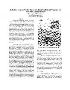
This paper aims to propose vehicle collision warning strategy based on the DSRC. This paper is organized as follows. The GPS coordinate transformation and Vehicle model are discussed in section 2. Approaching to predict the vehicle trajectory is deduced in section 3, and the collision warning strategy is deduced in section 4. The simulation verification was designed to examine the effectiveness of approaching index for collision avoidance in section 5. Finally, the conclusion is put forward in section 6. 2. The vehicle model and coordinate transformation 2.1. Vehicle Model and Vehicle-Coordinate Converted to Geodetic-Coordinates The vehicle dynamics model is a nonlinear system as shown in Fig.1. The roll, pitch, and vertical movement of the vehicle is ignored [7].
Figure 1. Vehicle model
Figure 2. Vehicle trajectory
2
ACMME 2018 IOP Publishing IOP Conf. Series: Materials Science and Engineering 394 (2018) 032110 doi:10.1088/1757-899X/394/3/032110 1234567890‘’“”
Where the coordinates ( X , Y ) denote the vehicle's centre of gravity in geodetic coordinates, the coordinates ( X v , Yv ) denote the vehicle's centre of gravity in vehicle coordinates, Vv , , , denote the vehicle’s speed, slip angle, the angle between geodetic and vehicle coordinates and yaw rate respectively. The vehicle-coordinate is shown in the following formula:
X cos , sin X v Y sin , cos Y v
(1)
2.2. GPS-Coordinates Converted to Geodetic-Coordinates The Global Positioning System (GPS) can meet the precise positioning for the vehicle. Currently, most of the vehicle onboard navigation systems use the U.S. GPS positioning system. The GPS location information received by the vehicle are longitude and latitude, which requires coordinate conversion. Considering the time efficiency of the transformation, Gaussian coordinate conversion method is adopted [8]. Gaussian coordinate transformation is shown in the following formula: 1 1 X X 0 Nt m 2 5 t 2 9 2 4 4 m 4 2 24 1 1 Y N m 1 t 2 2 m3 (5 18t 2 t 4 )m5 6 120
(2)
X 0 111134.861B (32005.780 sin B 133.924 sin 3 B 0.697 sin 5 B ) cos B
(3)
Where, B, L denote the Latitude and longitude of the vehicle, a, b denote the long radius and the short radius of the earth, e, e ' denote the first and second eccentricity ratio e ( a 2 b 2 ) / a 2 , e ' ( a 2 b 2 ) / b 2 , c a 2 / b, e ' cos B, V 1 2
.
N c / V , t tan B, m cos B( L /180) By the above coordinate’s transformation, all relevant vehicle information about the position, velocity is converted to the geodetic-coordinates system. 3. Vehicle trajectory prediction based on Adaptive Extended Kalman Filtering GPS can continuously provide the vehicle location information. The satellite signals are blocked by obstacles such as the tall buildings. Especially vehicle driving among the dense tall buildings in the city, the received GPS information have a larger error. It leads that vehicle location information is not available only by GPS information. Therefore, a precise vehicle position and trajectory prediction method based on the information fusion and AEKF strategy is proposed [9, 10].The location information of GPS and dynamical information obtained by onboard sensors are filtered and fused. The vehicle’s state of motion can be estimated by a position X , Y , velocity Vx , Vy , acceleration a , and heading angle ( ) as shown in the fig.2; it is assumed that every vehicle has the same dynamics model. The discrete time state equations of a vehicle are as follows:
3
ACMME 2018 IOP Publishing IOP Conf. Series: Materials Science and Engineering 394 (2018) 032110 doi:10.1088/1757-899X/394/3/032110 1234567890‘’“”
(i ) Vt 1 2 ) X (ti 1 ) X (ti ) [v(ti )Vt a(ti )Vt ]cos((i ) 2 2 (i ) Vt 1 2 Y (ti 1 ) Y (ti ) [v(ti )Vt 2 a(ti )Vt ]sin((i ) 2 ) v(t ) v(t ) a(t )Vt i i i 1 (ti 1 ) (ti ) (ti )Vt a (ti ) a (ti 1 ) (ti 1 ) (ti )
(4)
In the above equation, position X , Y obtained by the GPS, vehicle speed velocity Vx , Vy , acceleration a and yaw angular velocity can be obtained accurately through the vehicle on-board sensor. But the heading angle cannot be obtained through the vehicle sensor. Although the heading angle can be calculated by the yaw angular velocity, the error becomes larger with the accumulation of time. To get a more accurate heading angle, the error accumulation can be eliminated by AEKF. Adaptive Extended Kalman Filter (AEKF) can deal with statistics state estimation problem of nonlinear systems in which the noise is unknown. AEKF can compensate for the error of linear model through the real-time statistics of the unknown time-varying [11, 12]. The AEKF performs better in aspects of convergence, tracking accuracy and stability than Extended Kalman Filter (EKF).
yk
x k 1
xk
xk
Q
R
q
r
Figure 3. Adaptive Extended Kalman Filter The vehicle state vector is assumed to be x , the vehicle measure vector is y . The equation of state and the equation of measurement are shown as below:
x(t 1) (t ) x(t ) u (t ) y (t ) H (t ) x(t ) z (t )
4
(5)
ACMME 2018 IOP Publishing IOP Conf. Series: Materials Science and Engineering 394 (2018) 032110 doi:10.1088/1757-899X/394/3/032110 1234567890‘’“”
x(t 1) x(t 1 t ) K (t 1) (t 1)
x(t 1 t ) ( x(t ), t ) q(t )
(t 1) y (t 1) h( x(t 1 t ), t 1) r (t )
(6) 1
K (t 1) P (t 1 t ) H (t )[ H (t 1) P (t 1 t ) H (t ) R(t )] T
T
P(t 1 t ) (t ) P(t t )T (t ) Q(t ) P(t 1 t 1) [ I n K (t 1) H (t 1)]P(t 1 t )
q (t 1) (1 d t ) q (t ) d t [ x(t 1) ( x(t ), t )]
Q (t 1) (1 dt ) Q (t ) dt [ K (t 1) (t 1) T (t 1) K T (t 1) P(t 1 t 1) (t ) P (t t )T (t )]
r (t 1) (1 dt ) r (t ) dt [ y (t 1) h( x(t 1 t ), t 1)]
(7)
R (t 1) (1 dt ) R (t ) dt [ (t 1) T (t 1) H (t 1) P (t 1 t ) H T (t 1)] t 1
Where: d t (1 b) /(1 b ), 0 b 1 , b is forgotten factor, 0.95 b 0.995 . The vehicle state matrix and measurement matrix are as follows: 1 0 0 0 0 0 T ( i )
0 Vt cos(T ) Z sin(T ) 1 Vt sin(T )
Z cos(T )
0
1
0
0 0 0
0 0 0
1 0 0
(i ) Vt 2
1 2 Vt Vt cos(T ) Z sin(T ) 2 2 1 2 Vt Z cos(T ) Vt sin(T ) 2 2 0 Vt 0 Vt 1 0 0 1
1 0 0 H 0 0 0
0 0 0 0 0 1 0 0 0 0 0 1 0 0 0 0 0 1 0 0 0 0 0 1 0 0 0 0 0 1
1 , Z v(ti )Vt a (ti )Vt 2 2
4. Collision detection method The vehicle area is considered as a circle model as fig.4, which the centre is the mass centre of the vehicle, and the diameter is the wheelbase. Each vehicle exchanges the information through V2V wireless communication [13, 14].
5
ACMME 2018 IOP Publishing IOP Conf. Series: Materials Science and Engineering 394 (2018) 032110 doi:10.1088/1757-899X/394/3/032110 1234567890‘’“”
Y ( X B1 YB1 )
( X B2
YB 2 )
( X A2
YA 2 )
Ldis tan ce (ti 1 ) Ldis tan ce (ti )
( X A1 YA1 )
O
X Figure 4. Vehicle area model
Time to collision (TTC) is used to detect the danger of vehicle collision [15]. The safety time to collision is the minimum time required to avoid collision including the reaction time of the driver and the time to control the vehicle (steering, braking)[16]. By determining these parameters, the vehicle safety time to collision can be calculated. The minimum TTC [17] is calculated as follows:
( X A (ti 1 ) X B (ti 1 ) (YA (ti 1 ) YB (ti 1 ) 2
vdis tan ce (ti 1 )
2
Ldis tan ce (ti 1 )
Ldis tan ce (ti 1 ) Ldis tan ce (ti ) t
TTC t1 t2 t3 t4 ,
t4
Ldis tan ce Ra Rb vdis tan ce
(8)
(9)
(10)
Where, t1 is the reaction time of the driver, t2 and t3 are the reaction and action time of the brake system, t4 is the time it takes the car to slow down and stop. t1 1.5s, t2 0.2s, t3 0.2s . Ldis tan ce Is the linear distance between vehicle A and vehicle B. vdis tan ce is the rate of the Ldis tan ce . The fixed TTC warning threshold time is set as below: TTC 3s Warn, 3s TTC 5 s Hint, TTC 5 s No hint. 5. Simulation experiment To simulate the real driving condition of a city road, the collision is divided into three scenarios as the rear collision, front collision and side collision. Based on the software environment of CarSim, the simulation experiments of the front and rear collision scenarios on straight lines and side collision on the intersections are completed in this paper. The sensor data was obtained by the virtual sensor of CarSim software and imported into Matlab/Simulink software. The result as follows:
6
ACMME 2018 IOP Publishing IOP Conf. Series: Materials Science and Engineering 394 (2018) 032110 doi:10.1088/1757-899X/394/3/032110 1234567890‘’“”
Figure 5. Rear collision
Figure 6. Front collision
60 50 40 Vehicle A
30
Vehicle B
20 10 0 1
51 101 151 201 251 301 351 401 451
Figure 7. Side collision From the above figure, vehicle A is the controlled vehicle, vehicle B is reference vehicle. When the vehicle B steers, the algorithm can hint or warn the driver before the accident according to the time
7
ACMME 2018 IOP Publishing IOP Conf. Series: Materials Science and Engineering 394 (2018) 032110 doi:10.1088/1757-899X/394/3/032110 1234567890‘’“”
range of TTC. The simulation experiment is presented to illustrate the feasibility and effectiveness of this method. 6. Conclusion This paper proposes a precise vehicle conflict detection algorithms. The information fusion method based on GPS and vehicle sensors solve the inaccurate position of vehicles caused by GPS signal loss. AEKF solves the problem of trajectory prediction distortion due to error accumulation. The TTC warning algorithm is simple, feasible, and time-efficient and meets the real-time requirements for vehicles. References [1] Cicchino, J.B., Effectiveness of forward collision warning and autonomous emergency braking systems in reducing front-to-rear crash rates. Accid Anal Prev, 2017. 99 (Pt A): p. 142 - 152. [2] So, J., et al., Development and evaluation of an enhanced surrogate safety assessment framework. Transportation Research Part C: Emerging Technologies, 2015. 50: p. 51 - 67. [3] Tak, S., S. Woo, and H. Yeo, Study on the framework of hybrid collision warning system using loop detectors and vehicle information. Transportation Research Part C: Emerging Technologies, 2016. 73: p. 202 - 218. [4] Kenney, J.B., Dedicated Short-Range Communications (DSRC) Standards in the United States. Proceedings of the IEEE, 2011. 99 (7): p. 1162 - 1182. [5] Muhammad, M. and G.A. Safdar, Survey on existing authentication issues for cellular-assisted V2X communication. Vehicular Communications, 2018. 12: p. 50 - 65. [6] Golestan, K., et al., Localization in vehicular ad hoc networks using data fusion and V2V communication. Computer Communications, 2015. 71: p. 61 - 72. [7] Chang, B.R., H.F. Tsai, and C.-P. Young, Intelligent data fusion system for predicting vehicle collision warning using vision/GPS sensing. Expert Systems with Applications, 2010. 37 (3): p. 2439 - 2450. [8] Chen, L.S., Ren, J.S., Transfer Algorithm of WGS 84,Beijing 54 and Guass-Kruger Coordinate System. Aerospace Shanghai, 2013. 30 (5): 62 - 64. [9] Ghaleb, Fuad A., et al., Improved vehicle positioning algorithm using enhanced innovation-based adaptive Kalman filter. Pervasive and Mobile Computing, 2017. 40: p. 139 - 155. [10] Liu, J., B.-g. Cai, and J. Wang, Cooperative Localization of Connected Vehicles: Integrating GNSS With DSRC Using a Robust Cubature Kalman Filter. IEEE Transactions on Intelligent Transportation Systems, 2017. 18 (8): p. 2111 - 2125. [11] Liu, Y., et al., An innovative information fusion method with adaptive Kalman filter for integrated INS/GPS navigation of autonomous vehicles. Mechanical Systems and Signal Processing, 2018. 100: p. 605 - 616. [12] Wang, Y., et al., A DSRC-Based Vehicular Positioning Enhancement Using a Distributed Multiple-Model Kalman Filter. IEEE Access, 2016. 4: p. 8338 - 8350. [13] Chen, Y.L., et al., Inexpensive Multimodal Sensor Fusion System for Autonomous Data Acquisition of Road Surface Conditions. IEEE Sensors Journal, 2016. 16 (21): p. 7731 - 7743. [14] Elgharbawy, M., et al., A real-time multisensor fusion verification framework for advanced driver assistance systems. Transportation Research Part F: Traffic Psychology and Behaviour, 2017. [15] Haroun, A., A. Mostefaoui, and F. Dessables, Data fusion in automotive applications. Personal and Ubiquitous Computing, 2017. 21 (3): p. 443 - 455. [16] Melendez-Pastor, C., R. Ruiz-Gonzalez, and J. Gomez-Gil, A data fusion system of GNSS data and on-vehicle sensors data for improving car positioning precision in urban environments. Expert Systems with Applications, 2017. 80: p. 28 - 38. [17] Wang, H., et al., Real time implementation of socially acceptable collision avoidance of a low speed autonomous shuttle using the elastic band method. Mechatronics, 2018. 50: p. 341 - 355.
8