AbstractâA transistor-type heater is presented, which has been developed to regulate the temperature of microhotplates in industrial CMOS technology.
IEEE ELECTRON DEVICE LETTERS, VOL. 26, NO. 5, MAY 2005
295
Transistor Heater for Microhotplate-Based Metal–Oxide Microsensors M. Graf, S. K. Müller, D. Barrettino, Member, IEEE, and A. Hierlemann, Member, IEEE
Abstract—A transistor-type heater is presented, which has been developed to regulate the temperature of microhotplates in industrial CMOS technology. The heating transistor preserves its transistor characteristics up to 350 C and shows almost linear heating characteristics at temperatures higher than 100 C. The temperature can be controlled by adjusting the transistor source/gate voltage. Sensor measurements for CO are presented in two different sensing modes: chemoresistive readout and calorimetric readout by means of monitoring changes in the source/gate voltage which is required to keep the microhotplate temperature at the preset value. The device is part of an approach to monolithically integrate metal–oxide chemical sensors with circuitry. Index Terms—Metal–oxide gas sensor, microhotplate, MOSFET heater.
I. INTRODUCTION
T
HE research on metal–oxide-based gas sensors currently follows three major trends: 1) the nano- and microtechnological fabrication of sensitive layers [1]–[5]; 2) the fabrication of so-called “microhotplates,” which provide the sensitive-layer typical operating temperatures of 250 C–350 C at low power consumption [6], [7]; and 3) the integration of smart sensor features such as temperature controllers, readout circuitry, and signal conditioning with the sensors [8]. Following all three approaches to devise single-chip systems leads to a new generation of miniaturized devices with high functionality [9]–[11]. Most microhotplates to date rely on a resistor as heating element [6], [7]. Driving the heating current under the temperature controller output requires an on-chip power transistor [10], [11]. The voltage-drop across this transistor leads to a massive fraction of the overall power being dissipated in the power transistor, and not contributing to heating the hotplate. In contrast, CMOS technology allows for the direct use of a transistor as heater. Any heat dissipated in the transistor directly contributes to heating the hotplate. The system power consumption is reduced, chip area is saved, and digital heating schemes are facilitated. Moreover, a novel calorimetric-type sensing mode becomes feasible as will be detailed below, so that such microhotplates will further promote the miniaturization and integration efforts in metal–oxide-based sensor systems. To date, active transistor heating elements on a thermally isolated microstructure have been used for circuit temperature stabilization up to 90 C [12], [13]. High-temperature microhot-
Manuscript received January 7, 2005. The review of this letter was arranged by Editor J. Sin. The authors are with the Physical Electronics Laboratory, Swiss Federal Institute of Technology, CH-8093 Zurich, Switzerland (e-mail: mgraf@iqe. phys.ethz.ch). Digital Object Identifier 10.1109/LED.2005.846899
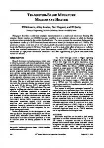
Fig. 1. (A) Cross-sectional view of a microhotplate with integrated pMOStransistor heater and (B) micrograph of the inner section of the microhotplate.
plates have been fabricated in silicon-on-insulator (SOI) CMOS technology [14], [15]. However, this technology is costly, and significant mechanical stress occurs in the membrane owing to the buried oxide, which can cause stability problems. No examples of transistor-heated microhotplates in conventional CMOS technology have been reported on so far, since it was anticipated that the needed operation temperatures cannot be reached with such a device due to the fact that an increased leakage current in the diode insulation occurs [16], [17]. To circumvent this problem, a microhotplate with an n-well Si-island in the center has been fabricated by using an electrochemical etch stop technology [18]. A pMOS heating transistor can then be placed on the n-well island, which is thermally and electrically insulated from the bulk chip. The transistor heating element preserves transistor properties up to operating temperatures of 350 C, as will be presented in this letter. II. EXPERIMENTAL A schematic view of the microhotplate with transistor heater is shown in Fig. 1(a). In order to ensure a good thermal insulation, only the dielectric layers of the CMOS process form the membrane. The inner section of the membrane includes a n-well silicon island underneath the dielectric layers. The n-well is electrically insulated and serves as heat spreader owing to the good thermal conductivity of silicon. It also hosts the pMOStransistor heating element (5 m gate length and 710 m overall
0741-3106/$20.00 © 2005 IEEE
296
IEEE ELECTRON DEVICE LETTERS, VOL. 26, NO. 5, MAY 2005
Fig. 2. Measurement of membrane temperature, T voltage, U , for different source/drain voltages, U .
versus source/gate
gate width). A special ring-shape transistor arrangement was chosen for homogeneous heat distribution. A polysilicon resistor is used to measure the temperature on the microhotplate. The resistance of the nanocrystalline SnO thick-film layer is read out by means of two noble-metal-coated (Pt) electrodes. The device fabrication relies on an industrial 0.8- m CMOS process (austriamicrosystems, Unterpremstätten, Austria) combined with post-CMOS micromaching steps [11]. The inner section of the membrane (500 500 m ) exhibits an octagonal-shape n-well silicon island (300 m base length). The octagonal shape provides a comparatively large distance between the heated membrane area and the cold bulk chip [close up in Fig. 1(b)]. Furthermore, this symmetric shape promotes homogeneous heat distribution. Two resistive polysilicon temperature sensors are implemented, one in the center ( ) and the other close to the heating transistor ( ). An additional resistive heater is implemented with the aim to have the possibility of in situ annealing of the sensitive material on the hotplate. The microhotplate with the transistor heater was electrothermally characterized. Special care was taken to exclude wiring series resistances by realizing on-chip pads that allow for an and accurate determination of the source/gate voltage . Both temperature sensors were the source/drain voltage calibrated in an oven prior to thermal characterization, and a second-order polynomial that describes the temperature characteristics was extracted. The relative temperature difference was taken as a measure for the temperature homogeneity over the heated area. III. RESULTS AND DISCUSSION A thermal resistance of C and a thermal was measured for a microhotplate time constant of without sensitive layer. The temperature homogeneity over the heated area was assessed to be better than 2% of the preset membrane temperature. Fig. 2 shows the microhotplate temperature versus source/ gate voltage for different source/drain voltages. As can be seen, temperatures even higher than 350 C were achieved with this MOS-transistor-heated membrane. The relationship between membrane temperature and source/gate voltage is
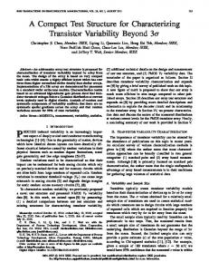
Fig. 3. Sensor signals of a MOSFET-heated microhotplate upon exposure to CO concentrations of 5 to 50 ppm at 40% r.h. (A) Sensor resistance. (B) Calorimetric signal monitored as source/gate voltage changes.
almost linear for temperatures above 100 C. This feature simplifies controlling the membrane temperature, and is, therefore, very interesting for the integration of the microhotplate in a monolithic sensor system with temperature controllers. The microhotplate was coated with a nanocrystalline thickfilm tin-oxide layer using a drop-coating method [19]. The sensitive material contains a minute fraction of 0.2 wt% of Pd, which renders the material more sensitive toward CO (material provided by AppliedSensor, Reutlingen, Germany). To characterize the chemical sensor performance, the chip was exposed to CO concentrations from 5 to 50 ppm in humidified air (40% r.h. at 23.4 C) in a chemical measurement setup [10], [11]. Fig. 3(a) shows the sensor responses upon gas exposure (CO) at exposure and purging intervals of 20 min. The membrane temperature was preset to 300 C. For better analyte discrimination, both the resistive sensor signal and eventual temperature changes (calorimetric signal) should be monitored and evaluated simultaneously [20], [21]. The temperature changes are a consequence of the chemical processes that occur during gas adsorption. These processes may either liberate heat or consume energy. The calorimetric signal, therefore, provides information about the reactions taking place and depends on the analyte nature, the sensing material characteristics, and the electrode layout. The calorimetric mode is not easy to realize with temperature-controlled microhotplates, since the purpose of the temperature controller is to keep the temperature constant. The calorimetric signal hence is only indirectly accessible via monitoring the heating current that is required to maintain the preset
GRAF et al.: TRANSISTOR HEATER FOR MICROHOTPLATE-BASED METAL–OXIDE MICROSENSORS
temperature. The MOSFET heater offers the possibility to measure the difference in the source/gate voltage that is necessary to maintain a preset constant temperature during analyte exposure of the sensor. The temperature control was realized by a Labview program, that reads out the resistance of the temperature sensor and adjusts the source/gate voltage accordingly so that this resistance and, consequently, the temperature is kept constant. Measurement results are plotted in Fig. 3(b). An increasing source/gate voltage indicates a larger heating power needed to maintain the preset temperature. A concentration step of 50 ppm results in a voltage step of 3 mV. This corresponds to a temperature change of 0.3 C. The noise in the signal is equivalent to 0.02 C temperature fluctuations. A similar experiment was performed with an uncoated microhotplate in the chemical measurement setup under the same measurement conditions. No changes in the source/gate voltage upon gas exposure were measured, so that the changes in the microhotplate heat budget are clearly related to the interaction of the analyte with the tin oxide. Consequently, calorimetric information can even be gained using a temperature-controlled microhotplate by monitoring gate voltage signals. ACKNOWLEDGMENT The authors thank Prof. H. Baltes (on leave) for sharing laboratory resources and for his ongoing stimulating interest in this work and AppliedSensor, Reutlingen, Germany, namely Dr. J. Kappler and Dr. S. Raible, for coating the microhotplates. REFERENCES [1] R. E. Cavicchi, J. S. Suehle, K. G. Kreider, B. L. Shomaker, J. A. Small, M. Gaitan, and P. Chaparala, “Growth of SnO films on micromachined hotplates,” Appl. Phys. Lett., vol. 66, pp. 812–814, 1995. [2] B. Panchapakesan, D. L. DeVoe, M. R. Widmaier, R. Cavicchi, and S. Semancik, “Nanoparticle engineering and control of tin oxide microstructures for chemical microsensor applications,” Nanotechnology, vol. 12, pp. 336–349, 2001. [3] E. Comini, G. Faglia, G. Sberveglieri, Z. W. Pan, and Z. L. Wang, “Stable and highly sensitive gas sensors based on semiconducting oxide nanobelts,” Appl. Phys. Lett., vol. 81, pp. 1869–1871, 2002. [4] N. O. Savage, S. Roberson, G. Gillen, M. J. Tarlov, and S. Semancik, “Thermolithographic patterning of sol-gel metal oxides on microhotplate sensing arrays using organosilanes,” Anal. Chem., vol. 75, pp. 4360–4367, 2003.
297
[5] M. Heule, S. Vuillemin, and L. J. Gauckler, “Powder-based ceramic meso- and microscale fabrication processes,” Adv. Mater., vol. 15, pp. 1237–1245, 2003. [6] I. Simon, N. Bârsan, M. Bauer, and U. Weimar, “Thermal and gassensing properties of a micromachined thermal conductivity sensor for the detection of hydrogen in automotive applications,” Sens. Actuators B, Chem., vol. 73, pp. 1–26, 2001. [7] J. Wöllenstein, J. A. Plaza, C. Cané, Y. Min, H. Böttner, and H. L. Tuller, “A novel single chip thin film metal oxide array,” Sens. Actuators B, Chem., vol. 93, pp. 350–355, 2003. [8] A. Hierlemann and H. Baltes, “CMOS-based chemical microsensors,” Analyst, vol. 128, pp. 15–28, 2003. [9] M. Y. Afridi, J. S. Suehle, M. E. Zaghloul, D. W. Berning, A. R. Hefner, R. E. Cavicchi, S. Semancik, C. B. Montgomery, and C. J. Taylor, “A monolithic CMOS microhotplate-based gas sensor system,” IEEE Sens. J., vol. 2, no. 2, pp. 644–655, May 2002. [10] M. Graf, D. Barrettino, M. Zimmermann, C. Hagleitner, A. Hierlemann, H. Baltes, S. Hahn, N. Bârsan, and U. Weimar, “CMOS monolithic metal- oxide sensor system comprising a microhotplate and associated circuitry,” IEEE Sens. J., vol. 4, no. 1, pp. 9–16, Jan. 2004. [11] M. Graf, D. Barrettino, S. Taschini, C. Hagleitner, A. Hierlemann, and H. Baltes, “Metal–oxide-based monolithic complementary metal oxide semiconductor gas sensor microsystem,” Anal. Chem., vol. 76, pp. 4437–4445, 2004. [12] R. J. Reay, E. H. Klaassen, and G. T. A. Kovacs, “Thermally and electrically isolated single crystal silicon structures in CMOS technology,” IEEE Electron Device Lett., vol. 15, no. 10, pp. 399–401, Oct. 1994. , “A micromachined low-power temperature-regulated bandgap [13] voltage reference,” IEEE J. Solid-State. Circuits, vol. 30, no. 12, pp. 1374–1381, Dec. 1995. [14] F. Udrea, J. W. Gardner, D. Setiadi, J. A. Covington, T. Dogaru, C. C. Lu, and W. I. Milne, “Design and simulations of SOI CMOS micro-hotplate gas sensors,” Sens. Actuators B, Chem., vol. 78, pp. 180–190, 2001. [15] J. A. Covington, F. Udrea, and J. W. Gardner, “Resistive gas sensor with integrated MOSFET micro hotplate based on an analogue SOI CMOS process,” in Proc. IEEE Sensors, Orlando, FL, 2002, pp. 1389–1394. [16] J. Goetz, “Sensors that can take the heat – Part I: Opening the hightemperature toolbox,” Sensors, vol. 17, no. 6, pp. 20–38, 2000. [17] , “Sensors that can take the heat – Part II: Support electronics and materials used in making high-temperature-tolerant circuits,” Sensors, vol. 17, no. 7, pp. 52–61, 2000. [18] T. Müller, M. Brandl, O. Brand, and H. Baltes, “An industrial CMOS process family adapted for the fabrication of smart silicon sensors,” Sens. Actuators A, Phys., vol. 84, pp. 126–133, 2000. [19] D. Briand, A. Krauss, B. van der Schoot, U. Weimar, N. Bârsan, W. Göpel, and N. F. de Rooij, “Design and fabrication of high-temperature micro-hotplates for drop-coated gas sensors,” Sens. Actuators B, Chem., vol. 68, pp. 223–233, 2000. [20] A. Heilig, N. Bârsan, U. Weimar, and W. Göpel, “Gas identification by modulating temperatures of SnO -based thick film sensors,” Sens. Actuators B, Chem., vol. 58, pp. 302–309, 1999. [21] T. Takada, “Temperature drop of semiconductor gas sensor when exposed to reducing gases – simultaneous measurement of changes in sensor temperature and in resistance,” Sens. Actuators B, Chem., vol. 66, pp. 1–3, 2000.