Jun 10, 2006 ... Computer-Aided Design Technology for VLSI. 2102545 Digital ... “Divide and
conquer” technique involves dividing a module into sub-modules ...
B.Supmonchai
June 10, 2006
B.Supmonchai
Outlines
VLSI Design Flow and Structural Design Principles
Tutorial 3
VLSI Design Styles
VLSI Design Methodology
VLSI Design Strategies
Computer-Aided Design Technology for VLSI
Boonchuay Supmonchai June 10th, 2006
2102545 Digital IC
Simplified VLSI Design Flows
B.Supmonchai
VLSI Design Methodology
2
B.Supmonchai
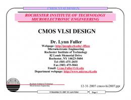
Four Levels of Design Representation
System Specification Behavioral Representation
Logic (Gate-Level) Representation
2102545 Digital IC
2102545 Digital IC
Functional (Architecture) Design
Circuit Design
Functional Verification
Circuit Verification
Logic Design
Physical Design
Logic Verification
Physical Verification
Front End
Back End
Synthesis Phase
Layout Phase
VLSI Design Methodology
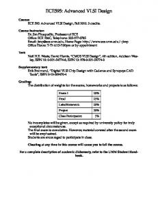
Circuit Representation
Behavioral Representation
Functional Blocks, FSM
Logic Blocks, Gates
Logic (Gate-Level) Representation Layout Representation
Circuit (Transistor-Level) Representation
Transistor Schematics
Layout Representation 3
2102545 Digital IC
Physical Devices VLSI Design Methodology
4
1
B.Supmonchai
June 10, 2006
Structure Design Principles
B.Supmonchai
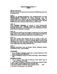
Example of Regularity
B.Supmonchai
Hierarchy: “Divide and conquer” technique involves dividing a module
into sub-modules and then repeating this operation on the submodules until the complexity of the smaller parts becomes manageable.
Regularity: The hierarchical decomposition of a large system should result
in not only simple, but also similar blocks, as much as possible. Regularity usually reduces the number of different modules
that need to be designed and verified, at all levels of abstraction. 2102545 Digital IC
These circuits are built using inverters and tri-state buffers only.
VLSI Design Methodology
5
B.Supmonchai
Structured Design Principles (Cont.)
2102545 Digital IC
VLSI Design Methodology
Example: 16-bit Adder Circuit
6
B.Supmonchai
Modularity: The various functional blocks which make up the larger
system must have well-defined functions and interfaces. Modularity allows each block to be designed independently;
All blocks can be combined with ease at the end of the process.
Locality: Internal details remain at the local level. The concept of locality also ensures that connections are
mostly between neighboring modules, avoiding long-distance connections as much as possible.
Structural Hierarchy of a 16-bit Manchester Adder 2102545 Digital IC
2102545 Digital IC
VLSI Design Methodology
7
2102545 Digital IC
VLSI Design Methodology
8
2
B.Supmonchai
June 10, 2006
Example (Cont.): Level 1
B.Supmonchai
B.Supmonchai
Example (Cont.): Level 2 Carry/propagate circuit
Output buffer/latch
16-bit Adder Complete Layout
Manchester Carry circuit
4-bit Adder with Manchester Carry Layout
4-bit Adder with Manchester carry 2102545 Digital IC
VLSI Design Methodology
9
Example (Cont.): Level 3
B.Supmonchai
2102545 Digital IC
VLSI Design Methodology
B.Supmonchai
Outlines
Carry/propagate circuit layout
Manchester carry circuit layout
10
VLSI Design Flow and Structural Design Principles
VLSI Design Styles
VLSI Design Strategies
Computer-Aided Design Technology for VLSI
Output buffer/latch circuit layout 2102545 Digital IC
2102545 Digital IC
VLSI Design Methodology
11
2102545 Digital IC
VLSI Design Methodology
12
3
B.Supmonchai
June 10, 2006
VLSI Design Styles
B.Supmonchai
Full-Custom Design
2102545 Digital IC
VLSI Design Methodology
Full-Custom Design Key Issues
13
B.Supmonchai
B.Supmonchai
Full-custom blocks are carefully crafted in the physical level to obtain the highest possible performance.
2102545 Digital IC
VLSI Design Methodology
Full-Custom DRAM Example
14
B.Supmonchai
The key to Full-custom design is to exploit the fine-grained regularity and modularity in the physical level. Manual full-custom design can be very challenging and time consuming, especially if the low level regularity is not well defined. Development cost are too high! Design reuse is becoming popular to reduce design
cycle time and development cost. ☞ IP blocks
Full-custom design is used only in the critical
blocks.
2102545 Digital IC
2102545 Digital IC
VLSI Design Methodology
15
2102545 Digital IC
VLSI Design Methodology
16
4
B.Supmonchai
June 10, 2006
Cell-Based Design
B.Supmonchai
Cell-Based Design Key Issues
“Lego” Style Design
All of the commonly used logic cells are developed, characterized, and stored in a standard cell library.
such as inverters, NAND, NOR, each in several versions to provide a range of performance.
The inverter gate can have standard size, double size, and quadruple size.
Most popular because of CAD tools availability and capability.
2102545 Digital IC
VLSI Design Methodology
Example of Standard Cells
Inclusion/Exclusion of a gate variation depends on the objectives of the library. Standard Library, Low Power Library, etc.
Library contains a certain numbers of basic cells
B.Supmonchai
17
B.Supmonchai
Most challenging task is to how to place the individual cells into rows and interconnect them in a way that meet stringent design goals. Most advanced CAD tools have place-and-route tools.
In a complex, demanding design, standard-cell based design approach may be used as a first pass, then full-custom design where necessary.
2102545 Digital IC
VLSI Design Methodology
18
Example of Stand Cells (Cont.)
Power Rail
B.Supmonchai
Standard Cell
Ground Rail
Routing Channel
Each cell layout is designed with a fixed height so that a number of cells can be “snapped” together side-by-side to form rows. 2102545 Digital IC
2102545 Digital IC
VLSI Design Methodology
19
2102545 Digital IC
VLSI Design Methodology
20
5
B.Supmonchai
June 10, 2006
Cell-Based Design Example
B.Supmonchai
B.Supmonchai
Masked Gate Array (MGA) Design
Only transistors No contacts and metal layers
One pattern mask for Mass production
2102545 Digital IC
VLSI Design Methodology
MGA Design Key Issues
21
B.Supmonchai
2102545 Digital IC
VLSI Design Methodology
Example of MGA Design
22
B.Supmonchai
“Uncommitted” (Unused) transistors or gates are wasted. Performance measured as Chip Utilization Factor ~
used chip area/total chip area.
Uncommitted cells can be sacrifices to improve intercell routing capability Modern GAs use multiple metal layers for channel routing Smaller area, higher density, and routability
2102545 Digital IC
2102545 Digital IC
VLSI Design Methodology
23
2102545 Digital IC
VLSI Design Methodology
24
6
B.Supmonchai
June 10, 2006
B.Supmonchai
FPGA Design
B.Supmonchai
Field Programmable Gate Array (FPGA)
An FPGA chip provides thousands of logic gates, organized into logic blocks, with programmable interconnects. To implement a custom hardware, a user can use high-level hardware programming (e.g., HDL). Program logic table for each logic block. Program interconnect switch matrices Program I/O blocks
Programs last as long as the chip is powered-on Architecture of Xilinx FPGAs VLSI Design Methodology
2102545 Digital IC
25
B.Supmonchai
FPGA (Cont.)
2102545 Digital IC
VLSI Design Methodology
26
B.Supmonchai
FPGA (Cont.)
Switch matrices and interconnection routing between CLB Simplified block diagram of a CLB by Xilinx 2102545 Digital IC
2102545 Digital IC
VLSI Design Methodology
27
2102545 Digital IC
VLSI Design Methodology
28
7
B.Supmonchai
June 10, 2006
FPGA Design Key Issues
B.Supmonchai
HDL-Based Design 1980’s
Chip utilization of an FPGA depends on
Hardware Description Languages (HDL) were conceived to facilitate the information exchange between design groups.
Granularity of the logic block - Size of logic block Routing capability - Size of switch matrices
The largest advantage of FPGA-based design is the very short turn-around time
1990’s
The increasing computation power led to the introduction of logic synthesizers that can translate the description in HDL into a synthesized gate-level net-list of the design.
The time required from the start of the design process until a functional chip is available
Typical price of FPGA chips is usually higher than other alternatives of the same design, but for small-volume production and for fast prototyping
2102545 Digital IC
VLSI Design Methodology
2000’s
Modern synthesis algorithms can optimize a digital design and explore different alternatives to identify the design that best meets the requirements. 29
B.Supmonchai
HDL-Based Design Methodology
2102545 Digital IC
2102545 Digital IC
VLSI Design Methodology
VLSI Design Methodology
31
30
B.Supmonchai
Outlines
2102545 Digital IC
B.Supmonchai
VLSI Design Flow and Structural Design Principles
VLSI Design Styles
VLSI Design Strategies
Computer-Aided Design Technology for VLSI
2102545 Digital IC
VLSI Design Methodology
32
8
B.Supmonchai
June 10, 2006
VLSI Design Strategies
B.Supmonchai
Product Life-Cycle
B.Supmonchai
Phenomenal growth rate in VLSI leads to a very complex and lengthy development of ICs. Design complexity increases almost exponentially
with the number of transistors to be integrated.
Efficient organization of all efforts is essential to the survival of a company. Teamwork Better tools Innovatives and creativities. Better Strategies
2102545 Digital IC
Products have a shorter life-cycle
VLSI Design Methodology
33
B.Supmonchai
Comparison of Design Strategies
2102545 Digital IC
VLSI Design Methodology
Comparison (Cont.)
34
B.Supmonchai
Freedom of Choices…. Cell Design
Custom Design
FPGA Design
2102545 Digital IC
2102545 Digital IC
VLSI Design Methodology
35
2102545 Digital IC
VLSI Design Methodology
36
9
B.Supmonchai
June 10, 2006
System-On-Chip (SOC) Design
B.Supmonchai
Example of SOC Design
B.Supmonchai
Integrating all or most of the components of a hybrid system on a single substrate (silicon or MCM), rather than building a conventional printed circuit board. Consequences: More compact system realization Less expensive!
Higher speed / performance Better reliability
Digital Video Processor 2102545 Digital IC
VLSI Design Methodology
Example of SOC Design (Cont.)
37
B.Supmonchai
2102545 Digital IC
VLSI Design Methodology
B.Supmonchai
Outlines
38
VLSI Design Flow and Structural Design Principles
VLSI Design Styles
VLSI Design Strategies
Computer-Aided Design Technology for VLSI
Each functional block can be reused block, IP (Intelectual Property) block, or custom-designed block. 2102545 Digital IC
2102545 Digital IC
VLSI Design Methodology
39
2102545 Digital IC
VLSI Design Methodology
40
10
B.Supmonchai
June 10, 2006
B.Supmonchai
Computer-Aided Design Technology
Synthesis Tools
CAD tools become more and more indispensable for timely development of ICs.
VHDL, Verilog, etc.
Determining the types and quantities of modules to
be included in the design using accurate estimate of lower level design features (area and delay).
Synthesis Tools (Synopsys®) Layout Tools (Cadence®) Simulation and Verification Tools 2102545 Digital IC
VLSI Design Methodology
B.Supmonchai
Layout Tools
41
Time spent on debugging and correcting a design has been increasing exponentially as each generation passed. Higher penalty is paid if a design flaw is detected
later in the design process.
Layout tools concern with the physical level of the design, i.e., how circuits are actually built on the IC: Standard Layout CAD tools are Floorplanning,
Simulation and verification are the most mature area
in VLSI CAD
Place-and-route, and Module generation
Sophisticated Layout CAD tools are goal driven and
include some degree of optimization functions
2102545 Digital IC
42
B.Supmonchai
Reliability issues: process variations, noise.
VLSI Design Methodology
VLSI Design Methodology
Simulation and Verification Tools
Circuit Optimization tools deal with the design in the transistor schematic levels:
2102545 Digital IC
Logic Synthesis and optimization tools can then be used to customize the design to particular needs, such as area minimization, low power, etc.
2102545 Digital IC
Transistor sizing for delay minimization
High-Level Synthesis tools automate the design phase in the top level of the design hierarchy: Based on Hardware-Description Languages (HDL)
Remember! ☞ CAD tools are good helpers for time-consuming and computation intensive mechanistic parts of the design, not the creative and inventive parts! CAD technology divides into three categories:
B.Supmonchai
43
Goal of all simulation tools is to determine if the design meets the required specifications at a particular design stage.
2102545 Digital IC
VLSI Design Methodology
44
11
B.Supmonchai
June 10, 2006
Simulation Tools (Cont.)
B.Supmonchai
Simulation tools used at various stages of the design process are Behavior simulation tools Logic Level simulation tools Complement logic synthesis and optimization tools.
Circuit-level simulation tools SPICE or derivatives such as HSPICE, PSPICE, etc.
Design Rule Checking tools Layout rule checking, Electrical Rule Checking (ERC), reliability rule checking. 2102545 Digital IC
2102545 Digital IC
VLSI Design Methodology
45
12