Broadcasting (CMMB) [3], Digital Terrestrial Multimedia. Broadcast (DTMB) [4], HomePlug AV (HPAV) [2], 3GPP. Long Term Evolution (LTE) [7], Digital Video ...
1
VLSI implementation of a multi-mode turbo/LDPC decoder architecture Carlo Condo, Maurizio Martina, Member IEEE, Guido Masera, Senior Member IEEE Dipartimento di Elettronica e Telecomunicazioni, Politecnico di Torino, Italy
Abstract—Flexible and reconfigurable architectures have gained wide popularity in the communications field. In particular, reconfigurable architectures for the physical layer are an attractive solution not only to switch among different coding modes but also to achieve interoperability. This work concentrates on the design of a reconfigurable architecture for both turbo and LDPC codes decoding. The novel contributions of this paper are: i) tackling the reconfiguration issue introducing a formal and systematic treatment that, to the best of our knowledge, was not previously addressed; ii) proposing a reconfigurable NoCbased turbo/LDPC decoder architecture and showing that wide flexibility can be achieved with a small complexity overhead. Obtained results show that dynamic switching between most of considered communication standards is possible without pausing the decoding activity. Moreover, post-layout results show that tailoring the proposed architecture to the WiMAX standard leads to an area occupation of 2.75 mm2 and a power consumption of 101.5 mW in the worst case. Index Terms—VLSI, LDPC/Turbo Codes Decoder, NoC, Flexibility, Wireless communications
I. I NTRODUCTION In the last years several efforts were spent to develop systems able to give ubiquitous access to telecommunication networks. These efforts were spent mainly in three directions: i) improving the transmission rate and reliability; ii) developing bandwidth efficient technologies; iii) designing low cost receivers. The most relevant results produced by such a vivid research were included in the last standards for both wireless and wired communications [1]–[7]. Besides, several standards provide multiple modes and functionalities. However, sharing common features is a challenging task to achieve flexibility and interoperability. Several recent works, including [8], have shown that flexibility is an important property in the implementation of communication systems. Some works investigated this direction facing the challenge of implementing flexible architectures for the decoding of channel codes. In particular, flexible turbo/Low-Density-Parity-Check (LDPC) decoder architectures have been proposed not only to support different coding modes within a specific standard but also to enable interoperability among different standards. In [9]– [11] flexibility is achieved through the design of Processing Elements (PEs) based on Application-Specific-Instruction-setProcessor (ASIP) architectures, whereas in [12]–[14] PEs rely on Application-Specific-Integrated-Circuit (ASIC) solutions. In both approaches, flexible and efficient interconnection structures are required to connect PEs to each other.
Unfortunately, the communication patterns of turbo and LDPC codes suffer from collisions, namely two or more PEs require concurrent access to the same memory resource. To break the collision a Network-on-Chip (NoC) like approach was proposed in [15] for turbo codes. This idea has been further developed in other works. In particular, in [16] the NoC approach is used as a viable solution to implement flexible and high throughput interconnection structures for turbo/LDPC decoders. An intra-IP NoC [17] is an application specific NoC [18] where the interconnection structure is tailored to the characteristics of the Intellectual Property (IP). The use of an intra-IP NoC as the interconnection framework for both turbo and LDPC code decoders has been demonstrated in several works [16], [19]–[21]. This choice enables larger flexibility with respect to other interconnection schemes [16], [22], [23], but introduces penalties in terms of additional occupied area and latency in the communication among PEs. Stemming from the work presented in [14], [19], [20], where an ASIC implementation of an NoC-based turbo/LDPC decoder architecture is proposed, this paper aims to further investigate and optimize it. In particular, this work features the following novel contributions: i) management of dynamic reconfiguration to switch between a code to another one without pausing the decoding, ii) description of a new PE architecture with an improved shared memory solution which provides relevant saving of occupied area for min-sum decoding algorithm, iii) evaluation of a wide set of standards for both wireless and wired applications: IEEE 802.16e (WiMAX) [5], IEEE 802.11n (WiFi) [6], China Mulitimedia Mobile Broadcasting (CMMB) [3], Digital Terrestrial Multimedia Broadcast (DTMB) [4], HomePlug AV (HPAV) [2], 3GPP Long Term Evolution (LTE) [7], Digital Video Broadcasting - Return Channel via Satellite (DVB-RCS) [1], iv) complete VLSI implementation of the decoder up to layout level and accurate evaluation of dissipated power. It is worth noting that, to the best of our knowledge, this is the first work addressing dynamic reconfiguration of flexible channel decoders with an analytical approach, and showing the actual impact of reconfiguration on both performance and complexity. The paper is structured as follows. In Section II decoding algorithms are briefly discussed, whereas section III deals with the basics of NoC-based turbo/LDPC decoder architectures and summarizes the main results this work starts from. The decoder reconfiguration techniques are detailed in Section IV and V, while Section VI deals with the description of LDPC and turbo decoding cores, along with their
respective memory organization. In Section VII evaluations of the architecture performance on various existing standards are provided. Implementation results are portrayed and discussed in Section VIII, and conclusions are drawn in section IX. II. D ECODING ALGORITHMS Turbo and LDPC decoding algorithms are characterized by strong resemblances: they are iterative, work on graphbased representations, are routinely implemented in logarithmic form, process data expressed as Logarithmic-LikelihoodRatios (LLRs) and require high level of both processing and storage parallelism. Both algorithms receive intrinsic information from the channel and produce extrinsic information that is exchanged across iterations to obtain the a priori information of uncoded bits, in the case of binary codes, or symbols, in the case of non binary codes. Moreover, their arithmetical functions are so similar that joint or derived algorithms for both LDPC and turbo decoding exist [24]. In the following for both codes we will refer to K, N and r = K/N as the number of uncoded bits, the number of coded bits and the code rate respectively. A. LDPC codes decoding algorithm Every LDPC code is completely described by its M × N parity check matrix H (M = N − K) which is very sparse [25]. Each valid LDPC codeword x satisfies H · x0 = 0, where (·)0 is the transposition operator. The decoding of LDPC codes stems from the Tanner graph representation of H where two sets of nodes are identified: Variable Nodes (VNs) and Check Nodes (CNs). VNs are associated to the N bits of the codeword, whereas CNs correspond to the M parity-check constraints. The most common algorithm to decode LDPC codes is the Belief Propagation (BP) algorithm. There are two main scheduling schemes for the BP: two-phase scheduling and layered scheduling [26]. The latter nearly doubles the converge speed as compared to two-phase scheduling. In a layered decoder, parity-check constraints are grouped in layers each of which is associated to a component code. Then, layers are decoded in sequence by propagating extrinsic information from one layer to the following one [26]. This process is iterated up to the desired level of reliability. Let λ[c] represent the LLR of symbol c and, for column k in H, bit LLR λk [c] is initialized to the corresponding received soft value. Then, for all parity constraints l in a given layer, the following operations are executed: λold k [c]
Qlk [c] = X Alk =
−
old Rlk
Ψ(Qln [c])
(1)
new 0 Rlk ≈ −δlk ·
min
n∈N (l),n6=k
{|Qnk |} ,
(6)
usually referred to as normalized-min-sum approximation, 0 where δlk = σ · δlk and σ ≤ 1. B. Turbo codes decoding algorithm Turbo codes are obtained as the parallel concatenation of two constituent Convolutional Code (CC) encoders connected by the means of an interleaver (Π). Thus, the decoder is made of two constituent decoders, referred to as Soft-In-SoftOut (SISO) or Maximum-A-Posteriori (MAP) decoders [28] connected in an iterative loop by the means of the interleaver Π and the de-interleaver Π−1 . Each constituent decoder performs the so called BCJR algorithm [29] that starting from the intrinsic and a priori information produces the extrinsic information. Let k be a step in the trellis representation of the constituent CC, and u an uncoded symbol. Each constituent apr u decoder computes λk [u] = σ · (λapo k [u] − λk [u] − λk [c ]) apo where σ ≤ 1 [30], λk [u] is the a-posteriori information, u λapr k [u] is the a priori information and λk [c ] is the systematic component of the intrinsic information. According to [29] aposteriori information is computed as ∗
∗
e:u(e)=u
e:u(e)=˜ u
λapo k [u] = max {b(e)} − max {b(e)}
(7)
where u ˜ ∈ U is an uncoded symbol taken as a reference (usually u ˜ = 0) and u ∈ U \ {˜ u} with U the set of uncoded symbols; e is a trellis transition and u(e) is the corresponding uncoded symbol. Several exact and approximated expressions ∗ are available for the max{xi } function [31]: for example, it can be implemented as max{xi } followed by a correction term, often stored in a small Look-Up-Table (LUT). The correction term, usually adopted when decoding binary codes (Log-MAP), can be omitted with minor Bit-Error-Rate (BER) performance degradation (Max-Log-MAP). The term b(e) in (7) is defined as: b(e) = αk−1 [sS (e)] + γk [e] + βk [sE (e)] � ∗ αk [s] = max αk−1 [sS (e)] + γk [e] e:sE (e)=s
(2) βk [s] =
n∈N (l),n6=k
Y
λold k [c] is the extrinsic information received from the previous layer and updated in (5) to be propagated to the succeedold ing layer. Term Rlk , pertaining to element (l,k) of H and initialized to 0, is used to compute (1); the same amount is new then updated in (4), Rlk , and stored to be used again in the following iteration. In (2) and (3) N (l) is the set of all bit indexes that are connected to parity constraint l. According to [27], the Ψ(·) function in (2) and (4) can be simplified with a limited BER performance loss as
∗
max
e:sS (e)=s
�
βk+1 [sE (e)] + γk [e]
(8) (9) (10)
(3)
γk [e] = λapr k [u(e)] + λk [c(e)]
new Rlk = −δlk · Ψ−1 (Alk )
(4)
new λnew [c] = Qlk [c] + Rlk k
(5)
where sS (e) and sE (e) are the starting and the ending states of e, αk [sS (e)] and βk [sE (e)] are the forward and backward metrics associated to sS (e) and sE (e) respectively. The term λk [c(e)] represents the intrinsic information received from the
δlk =
sgn(Qln [c])
n∈N (l),n6=k
(11)
RE i
read enable
Routing algorithm crossbar conf.
load
input
output
λi,j
Reconfiguration
PE i
λ0i,j
MEM i
Location Memory t0i,j
bus
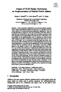
Figure 1. Node structure
channel. For further details on the decoding algorithm the reader can refer to [32]. In a parallel decoder, the decoding operations summarized in previous paragraphs are partitioned among P PEs. When configured in turbo code mode, these PEs operate as concurrent SISOs. On the other hand, they execute (1) to (5) in parallel for P slices of parity check constraints when configured in LDPC code mode. In both cases, messages are exchanged among PEs to propagate λk [u] and λnew [c] k amounts in accordance with the code structure. In the following, we indicate the j-th message received and generated by PE i as λ0i,j and λi,j respectively. III. N O C- BASED D ECODER The goal of this work is to design a highly flexible LDPC and turbo decoder, able to support a very wide set of different communication standards. The proposed multi-mode/multistandard decoder architecture relies on an NoC-based structure, where each node contains a PE and a routing element (RE). Each PE implements the BCJR and layered normalized min-sum algorithms. On the other hand, REs are devoted to deliver λi,j values to the correct destination. The node architecture employed in this work for node i is represented in Fig. 1. Each RE is constituted by a 4×4 crossbar switch with 4 input FIFOs and 4 output registers. The routing algorithm is the one proposed in [19] as Single-ShortestPath-FIFO-Length (SSP-FL). SSP-FL relies on a distributed table-based routing algorithm where each table contains the information for shortest path routing. The routing information is precalculated by running off-line the Floyd-Warshall algorithm. Moreover, in SSP-FL shortest path routing is coupled with an input serving policy based on the current status to the FIFOs, namely in case two messages must be routed to the same output port, priority is given to the message coming from the longer FIFO. It is worth noting that the destination of each λi,j is imposed by the interleaver and the H matrix respectively. As a consequence, the routing is deterministic. The PE includes both LDPC and turbo decoding cores: their architectures are structured to be as independent as
possible of the supported codes. The LDPC decoding core is completely serial and able to decode any LDPC code, provided that enough memory is available. The SISO core for turbo decoding is tailored around 8-state turbo codes, and no other constraints are present: the two cores share the memories where the incoming data λ0i,j are stored and the location memory containing the pre-computed t0i,j values, i.e. the memory addresses to store λ0i,j . Also the interconnection structure depends only on the location memory size, that sets an upper bound to the number of messages each PE can handle. The decoding task is divided uniformly among the different nodes. The process is straightforward in turbo mode, with each node being assigned a portion of the trellis that is processed in a sliding-window fashion [33], [34]. Extrinsic and window-initialization information are carried through the network according to the code interleaving and deinterleaving rules [19]. On the contrary, in LDPC mode the partitioning of the decoding task on the PEs is obtained as follows. Using a proprietary tool based on the METIS graph coloring library [35], the H matrix is partitioned on the chosen network topology. At this point the destination of every message coming out of each decoding core is known. Thus, in both turbo and LDPC modes each outgoing message is made of a payload λi,j and a header containing the destination node. Performance of meshes, toroidal meshes, spidergon, honeycomb, De Bruijn and Kautz graphs were compared, along with a number of other design choices, as routing algorithm and collision management policies. This analysis shows that the Kautz topology yields the best results in terms of area occupation and obtainable throughput. In particular, in [14] a 22-nodes Kautz NoC was used to fully support IEEE 802.16e standard, each node being connected to a decoding PE and to three other nodes via a 4-way router. IV. D ECODER R ECONFIGURATION Flexible decoders available in the literature [9]–[13], [16], [17], [19], [20], though supporting a wide range of codes, do not address the reconfiguration issue. Change of decoding mode, standard or code parameters requires not only hardware support, but also memory initialization and specific controls: since in many standards a code switch can be issued as early as one data frame ahead [5], a time efficient reconfiguration technique must be developed. For the proposed decoder the reconfiguration task consists of i) rewriting the location memory containing t0i,j values; ii) reloading the CN degree (deg) parameters and the window size in the control unit of LDPC decoding cores and SISOs respectively. In the following, the whole set of storage locations to be updated at reconfiguration time will be indicated as “reconfiguration memory”. When possible, the decoder must be reconfigured while the decoding process is still running on the previous data frame. This means that the reconfiguration data can be distributed by means of the NoC interconnections only at the cost of severe performance penalties. Consequently, we suppose that the reconfiguration data are moved directly to the PEs via a set of Nb dedicated buses, each one linked to NPb PEs.
Locations occupied by C1
Free locations
SCC
SCC
EFC RP
RP ECC
ECC
SFC
WP
(a)
111111 000000 000000 111111 000000 111111 000000 111111 000000 111111 000000 111111 000000 111111 111111 000000 000000 111111 000000 111111 000000 111111 000000 111111 000000 111111 000000 111111 000000 111111 000000 111111 000000 111111 000000 111111 (b)
11 00 00Locations uploaded with C2 11 00 11 00 11
ECC
SCC
RP
11111 00000 00000 11111 00000 11111 00000 11111 00000 11111 00000 11111 00000 11111 11111 00000 00000 11111 00000 11111 00000 11111 00000 11111 00000 11111 00000 11111 00000 11111 00000 11111 00000 11111 00000 11111 (c)
Figure 2. Memory reconfiguration process: (a) Decoding of C1 ; (b) Upload of reconfiguration data required for C2 (phases Φ1 to Φ3 and Φ5 ); (c) First iteration of C2 and concurrent upload of reconfiguration data (Φ4 )
In the following we estimate reconfiguration occurrence assuming mobile receivers moving at different speeds and the carrier frequency fc = 2.4 GHz. This frequency is included in most standards’ operation range, and used in a variety of applications. In this scenario the communication channel is affected by fading phenomena, namely slow fading, whose effects have very long time constants, and fast fading. Fast fading can be modeled assuming a change of channel conditions every time the receiver is moved by a distance similar to the wavelength λ of the carrier. Being λ = 0.125 m, at a speed v = 70 km/h the channel changes with a frequency fchng = 155 Hz (WiMAX, WiFi, 3GPP-LTE), whereas, at v = 10 km/h (DVB-RCS, HPAV, CMMB, DTMB) changes occurs at fchng = 22 Hz. These scenarios result in different reconfiguration probabilities, whose impact on BER performance is addressed in Section V. The reconfiguration memory is organized as a circular buffer: two sets of pointers are used to manage reading and writing operations. The Start of Current Configuration (SCC) pointer and the End of Current Configuration (ECC) pointer delimit the memory blocks that are currently being used. A Read Pointer (RP) is used to retrieve the data during the decoding process, as shown in Fig. 2.(a). The Start of Future Configuration (SFC) and End of Future Configuration (EFC) pointers are instead used concurrently with the Write Pointer (WP) to delimit the locations that are going to be used to store the new configuration data. The reconfiguration of the considered decoder to switch from the code currently processed (C1 ) to a new one (C2 ) can be overlapped with the decoding of both current and new code, provided that enough locations are free in the configuration memories. In particular, part of the configuration process can be concurrent with the decoding of one or more frames of C1 ; if necessary, another portion of the configuration can be scheduled during the first iteration of the new code C2 . Finally, in case the overlap with decoding activity is not sufficient to complete the whole configuration, a further option is pausing the decoder by skipping one or more iterations on the last received frame for C1 and using the available time, before starting the decoding of the new frame encoded with C2 .
Let us define B as the size of the location buffer available at each PE to store configuration data, tit1 and tit2 as the duration in clock cycles of a single decoding iteration for codes C1 and C2 . Moreover, lc1 and lc2 express the number of locations required to store configurations of codes C1 and C2 at each PE, and nit1 and nit2 their iteration numbers. In the considered architecture, the duration of one decoding iteration tit expressed in clock cycles is directly proportional to the number of memory locations a PE has to read throughout the decoding process, and consequently to the number of used locations in the reconfiguration memory (lc ). Though the actual relationship between tit and lc is affected by memory scheduling and ratio between PE and NoC clock frequencies, this analysis is carried out with the worst-case assumption that the reconfiguration memory is read at every clock cycle of each iteration, setting lc = tit for both C1 and C2 codes. We define five phases Φi , i = 1, 2, 3, 4, 5 in the configi uration process and for each phase we identify i) tΦ as a the number of clock cycles available during phase Φi , and i ii) laΦi = Nb · tΦ a /P as the number of locations in each i reconfiguration memory that can be written in tΦ a clock cycles. Φ1 In the reconfiguration from code C1 to code C2 , lc1 words must be replaced with lc2 new words. The first part of the configuration can be scheduled during the initial nit1 − 1 decoding iterations on C1 and therefore the available time 1 is tΦ a = (nit1 −1)·tit1 ; in this range of time a maximum Φ1 of la = NPb · (nit1 − 1) · tit1 words can be loaded into each buffer. However, assuming that the buffer size is larger than lc1 , we define B − lc1 as the number of unused memory blocks in current configuration for code C1 . Therefore, the actual number of locations written in Φ1 is the minimum between B − lc1 and laΦ1 . The SFC pointer is thus initialized as ECC (Fig. 2.(b)). Φ2 During the last iteration on C1 , every memory location between SCC and the current position of RP is available for reconfiguration. This means that up to lc1 locations are available for receiving configuration words for C2 . However, this has to be done during a single iteration, 2 and therefore tΦ a = tit1 cycles are available. During these Φ2 cycles, up to la = NPb · tit1 words can be loaded. Φ3 As mentioned before, part of the configuration can be overlapped with the first decoding iteration on C2 code. SCC is initialized as SFC, and RP will take the duration of a full iteration to arrive to ECC (Fig. 2.(c)). The 3 available time is tΦ a = tit2 and the maximum number of words that can be loaded in this phase is laΦ3 = NPb · tit2 . Φ4 In the event that previously listed phases are not sufficient to complete the configuration, an early stopping in the decoding of code C1 can be scheduled to make available additional cycles to be used for loading the remaining part of the configuration words. We indicate the number of 4 cycles available in this phase as tΦ a = tstop . The number of words that can be loaded in Φ4 is laΦ4 = NPb · tstop . As one or more complete iterations are dropped in Φ4 , tstop is a multiple of tit1 , which can be formalized as tstop = nstop · tit1 ,
nstop = 0, 1, 2, 3, · · ·
(12)
Differently from the other four phases, Φ4 affects the
Table I Φ R ECONFIGURATION PHASES Φi : ta i , AVAILABLE CLOCK CYCLES DURING Φi Φ Φi AND la NUMBER OF LOCATIONS THAT CAN BE WRITTEN IN ta i Φ ta i
Φ1 Φ2 Φ3 Φ4 Φ5
Φ5
(nit1 − 1) · tit1 tit1 tit2 tstop nit1 · tit1 · Nf
Nb P
· (nit1 − 1) · tit1 Nb · tit1 P Nb · tit2 P Nb · tstop P Nb · nit1 · tit1 · Nf P
laΦ5
Φ5 1 tΦ a + ta ≤
Nb ·nit1 ·tit1 ·Nf (13) = P
P · (B − lc1 ) Nb
Nb · nit1 · (1 + Nf ) · lc1 P − Nb
(18)
A number Nf of preceding frames can be exploited only if enough locations are unused in the buffers during Φ1 and Φ5 . This condition can be expressed as
The five described phases are reported in Table I, together Φi i with the corresponding tΦ a and la . Thus, B, Nb , nstop and Nf are design parameters, and their values must be decided based on decoder parallelism (P) and supported codes, which determine lc1 and lc2 . Two alternative cases can arise during Φ1 : either this phase is limited by the available time, or it is limited by the number of free locations in the reconfiguration memory: (nit1 − 1) · tit1 R
lc2
0 the number of decoding iterations is reduced for code C1 . Evaluating the actual effect on BER and FER curves is necessary to understand the feasibility of this approach. If necessary, the reconfiguration process can be overlapped with the decoding of a number Nf of data frames encoded with C1 , in addition to the last frame, which was already considered in Φ1 . The available time depends on the chosen Nf : 5 tΦ a = nit1 ·tit1 ·Nf ,
Then, if tit2 = lc2 , we have
(14)
P · (B − lc1 ) Nb
(19)
namely (nit1 − 1) · tit1 + nit1 · tit1 · Nf ≤
P · (B − lc1 ). Nb
(20)
Thus, given that tit1 = lc1 , the maximum useful value of Nf depends on lc1 as Nf (lc1 ) ≤
P Nb
· (B − lc1 ) − (nit1 − 1) · lc1 nit1 · lc1
, N fmax (21)
Thus, (18) can be better written as lc2
70 Mb/s) can be LDP C turbo obtained with fcore = 200 MHz and fcore = 80 MHz. Table II summarizes the results. • IEEE 802.11n: IEEE 802.11n standard [6] requires a higher throughput than WiMAX, demanding for the N = 1944, r = 5/6 code up to 450 Mb/s. The 22–node architecture can guarantee it with fcore = 820 MHz. Taking in account the fcore /fN oC ratio constraint, this would mean fN oC = 1.23 GHz. Both frequencies are over the decoder maximum working frequency, and two alternatives have been devised. By increasing the size of the NoC to 35 nodes, the fcore /fN oC still holds at 2/3,
fcore [MHz] 80 200 200 200 200
•
•
•
r=1/2 r=2/3 r=3/4 r=5/6
@520 MHz 35 nodes 248 364 406 455
T [Mb/s] @350 MHz 35 nodes 167 245 273 306
@200 MHz 22 nodes 60 88 94 110
DVB-RCS: the return channel for DVB satellite communications [1], thought for multimedia applications, employs 12 different payloads and 7 coding rates. The throughput required by this standard is very small, and can go up to 2.05 Mb/s in case of corporate-driven applications. This throughput is easily sustained by the 22-node architecture with fcore = 3 MHz. HomePlug AV: the HPAV standard [2] makes use of a small set of DBTC, with interleaver sizes of 64, 544 and 2080. The throughput requirements of HPAV demand at least 150 Mb/s: on the 22-node architecture, with fcore = 170 MHz, achieved throughput is 156 Mb/s. CMMB and DTMB: the CMMB [3] and DTMB [4] Chinese broadcast standards, though serving the same purposes as DVB, work with smaller LDPC codes. Like in DVB, also in CMMB codes feature double diagonal submatrices, slightly limiting the concurrent number of row nodes that can be instantiated on the proposed decoder. Both CMMB and DTMB codes demand an increased memory capacity with respect to the aforementioned standards, requiring PE memories to be enlarged by 55% to support CMMB, and by 68% for DTMB. A working frequency fcore = 60 MHz is sufficient to guarantee the 20.22 Mb/s throughput required by CMMB standard, while to comply with DTMB 40.6 Mb/s, frequency must be risen to fcore = 200 MHz, as shown in Table V. 3GPP-LTE: the LTE version of 3GPP [7] uses a set of 188 SBTC with coding rate 1/3, thus being characterized by a range of widely spaced block lengths. The required 150 Mb/s throughput can be obtained on the 22-node
Table IV R ECONFIGURATION CASES IN INTRA - AND INTER - STANDARD COMBINATIONS . DARK GRAY: PERCENTAGE OF CODE COMBINATIONS REQUIRING DECODER PAUSING . L IGHT GRAY: PERCENTAGE OF CODE COMBINATIONS REQUIRING 0 < Nf ≤ 2. W HITE : ALL CODE COMBINATIONS RECONFIGURABLE WITH Nf = 0. T HROUGHPUT OBTAINED WITH 10 ITERATIONS FOR LDPC, 8 FOR T URBO
C2 C1 WiMAX LDPC WiMAX turbo WiFi DVB-RCS HPAV CMMB DTMB 3GPP-LTE
WiMAX LDPC
WiMAX turbo
WiFi
DVB-RCS
HPAV
CMMB
DTMB
3GPP-LTE
3.5% 10.1% 8.2% 18.5% 14.4%
8.2% 15.8% 13.2% 0.3% 17.6%
1.8% 4.4% 6.8% 13.5% 11.1%
2.4% 5.9% 4.0% 8.5% 17.8%
14.0% 17.6% 19.4% 22.2% 33.3%
21.0% 47.0% 33.3% 55.9% 33.3%
36.4% 54.9% 44.4% 67.0% 77.7%
5.2% 10.0% 6.8% 13.5% 12.3%
7.9%
10.0%
5.3%
4.2%
12.3%
31.6%
38.0%
6.8%
Table V CMMB AND DTMB STANDARD THROUGHPUT (T ), 10 ITERATIONS CODE CMMB LDPC r=1/2 CMMB LDPC r=3/4 DTMB LDPC r=2/5 DTMB LDPC r=3/5 DTMB LDPC r=4/5
fcore [MHz] 60 60 200 200 200
T [Mb/s] 22 33 42 55 68
architecture with fcore = 330 MHz; however, if we consider the extended 35-node architecture mentioned for the WiFi standard, compliance with the throughput requirement is met at fcore = 200 MHz. This standard requires additional 41% memory capacity w. r. t. WiMAX, WiFi, DVB-RCS and HPAV standards, but can be fully supported by the CMMB and DTMB memory sizing. Table IV summarizes possible switching among the selected standards, taking in account all possible code combinations. The dark gray cells represent the percentages of C1 , C2 combinations between two standards whose reconfiguration requires pausing of the decoder. A few cases arise between DVB-RCS and WiMAX turbo codes and within 3GPP-LTE (due to its wide variety of codes), while when C2 belongs to the CMMB, DTMB and LTE standards, it is more likely to encounter a critical combination. On the contrary, if C1 belongs to CMMB or DTMB standards, any reconfiguration can be completed with Nf = 0: this is also the most common situation among the other standards. The choice of maximum Nf = 2 allows to handle all the other reconfiguration cases: the light gray cells show the percentages of code combinations in which 0 < Nf ≤ 2 is necessary. VIII. I MPLEMENTATION R ESULTS The results presented in Section VII show a broad range of possibilities for implementation, and the designed decoder can be scaled with very low effort. Three different complete decoders have been synthesized with TSMC 90 nm CMOS technology: post-layout results have been obtained for all of them, with accurate functional verification, area and power estimation. Synthesis has been carried on with Synopsys
Design Compiler, functional simulation with Mentor Graphics ModelSIM, and place and route with CADence SoC Encounter [38]. A. Implementation A The first decoder implementation has been devised to fully support WiMAX, HPAV and DVB-RCS standards. The memory sizing and organization described in Section VI-A is able to handle the addressed standards with 22 PEs. To comply with each standard throughput requirements, a single fN oC = 300 MHz is sufficient in both LDPC and turbo mode, consequently turbo LDP C = 170 MHz, = 200 MHz and fcore identifying fcore both under the fcore /fN oC constraint. Obtained throughput is presented in Table VI. Each reconfiguration bus is 18 bits wide: 3 bits are the node identifier, used to address one of the connected decoding cores, 5 bits are assigned to the node degree or window size information, and the remaining 10 bits carry the t0i,j . These design choices have led to an overall area of 2.75 mm2 after place and route, taking in account the reconfiguration additional hardware as well. The logic of the SISO cores occupies 15% of the overall area, while the LDPC cores 11%. Core memories account for another 53%, while the NoC, together with the reconfiguration buses and additional logic, constitute the remaining 21%. This area overhead is due to two specific functionalities that have been introduced in the proposed decoder: (i) full flexibility in terms of supported turbo and LDPC codes, and (ii) dynamic reconfiguration between different standards. Estimated power consumption, based on the switching activity in case of WiMAX LDPC code N = 2304, r = 1/2 (for ease of comparison with the state of the art) is 87.8 mW; for WiMAX turbo code with K = 2400 estimated power is 101.5 mW. A screenshot of the final layout is portrayed in Fig. 14: the irregularity of the placement is due to the large number of memories and their complex interconnections. However, two different areas can be easily identified: a central zone in which most of the logic is found (black contour), and a border area where the majority of memories have been placed, some of which are highlighted with a white line.
Table VI T HROUGHPUT (T ) RESULTS FOR EACH STANDARD , WITH EVERY IMPLEMENTATION
CODE STD, r
Figure 14. Implementation A layout screenshot
B. Implementation B The second implementation presented extends the set of standards supported by implementation A to WiFi LDPC codes and 3GPP-LTE turbo codes. To limit the complexity of off-chip clock generators, also in this case a single NoC working frequency has been chosen, fN oC = 780 MHz, LDP C while fcore = 520 MHz is necessary to provide high turbo can remain set to 200 MHz. The enough throughput, fcore parallelism of the NoC is increased from 22 nodes to 35 nodes, the reconfiguration buses rise from 5 to 8, and the support of LTE requires an increase in the size of 6-bit memories. Throughput results are reported in Table VI. The post place & route estimated area is 4.87 mm2 , with 331.6 mW of power consumption in LDPC mode, and 183.2 mW in turbo mode. C. Implementation C This third implementation extends implementation A’s support to CMMB and DTMB. Neither frequency nor NoC parallelism modification are necessary, but the core and reconfiguration memories must be enlarged. Consequently, an extra bit is added to the reconfiguration bus data width. The new post place & route estimated area is 3.42 mm2 , while power reaches 120 mW for both tested turbo and LDPC codes. This is because the LDPC consumption is calculated on a DTMB code, that makes full use of the extended memories, while the memory usage percentages for DBTC remains low. The enlarged memories allow also LTE codes to be decoded, but the SBTC fcore would need to rise up to 333 MHz to meet the throughput requirements. Throughput results for CMMB and DTMB are shown in the Implementation C column of Table VI. D. Comparisons Table VIII shows the detailed implementation results in comparison with the state of the art flexible turbo/LDPC decoders. Even though A, B and C are the only decoders capable of dynamic switching, area, power and efficiency figures prove the effectiveness of this approach. In order to make a fair comparison, normalized area occupation has been included in the Table, Antot =Atot ·(65/Tp)2 , where Atot is the total area and Tp is the technology process, together with throughput and power consumption. Moreover, two further metrics have been introduced: the energy efficiency
Impl. A fN oC 300 MHz fcore T [MHz] [Mb/s]
T [Mb/s] Impl. B fN oC 780 MHz fcore T [MHz] [Mb/s]
Impl. C fN oC 300 MHz fcore T [MHz] [Mb/s]
DBTC WiMAX HPAV DVB-RCS
170 170 170
156 156 156
200 200 200
292 292 292
170 170 170
156 156 156
SBTC 3GPP-LTE
N/A
N/A
200
150
170
78
LDPC WiMAX 1/2 WiMAX 2/3 WiMAX 3/4 WiMAX 5/6 WiFi 1/2 WiFi 2/3 WiFi 3/4 WiFi 5/6 CMMB 1/2 CMMB 3/4 DTMB 2/5 DTMB 3/5 DTMB 4/5
200
200
70 88 88 110 60 88 94 110
520
520
289 364 364 455 248 364 406 455
200
200
N/A
N/A
N/A
N/A
200
N/A
N/A
N/A
N/A
200
(max)
70 88 88 110 60 88 94 110 73 110 42 55 68
Eef f = P ow/(T · nit ), where Pow is the peak power consumption, expressing the energy spent for decoded bit, and (max) the area efficiency Aef f = (T · nit /fclk ) · (1000/Antot ), reported in Table VII, an efficiency figure that considers both throughput and area occupation. Baghdadhi et al. in [11] propose an ASIP decoder architecture supporting WiMAX and WiFi LDPC codes, and WiMAX, 3GPP-LTE and DVB-RCS turbo codes. The A, B and C implementations are designed such that the minimum throughput is sufficient to comply with the supported standards. On the contrary, worst case throughput in [11] is not high enough for WiMAX. Comparison reveals similar area occupations, but very different frequencies. This leads to a better area efficiency in all three proposed implementations for most of the codes: particularly evident is the difference for DBTC (second last row of Table VII). The work presented in [9] supports convolutional, LDPC and turbo codes, giving results for WiMAX LDPC, WiFi and general binary and double-binary turbo codes. It yields a very small area occupation with low power consumption and good maximum throughput for LDPC decoding. On the contrary, it features less interesting figures in turbo mode. This situation is reflected both on Eef f and Aef f , with Implementation A, B and C having, when comparing the same codes, better efficiencies in turbo mode (last row of Table VII), and worse in LDPC mode. However, under the worst case conditions (N =672, r = 1/2, 20 iterations), A and B outperform [9] also in LDPC mode. The multi-standard decoder designed in [12] supports 3GPP-HSDPA, WiFi, WiMAX and DVB-SH. No specific information on the codes used is given, only minimum guaranteed throughput: for this reason, results in Table VII refer to the minimum throughput of each standard. Implementation A
Table VII A REA EFFICIENCY (Aef f ) FOR DIFFERENT CODES AND IMPLEMENTATIONS . N/A: CODE NOT SUPPORTED . DASH : RESULTS NOT AVAILABLE . Aef f [ mm2bits ] ·kcycles CODE
A
B
C
[11]
[9]
LDPC 2304, 1/2 2304, 5/6 1944, 5/6 7493, 4/5
2447 3846 3846 N/A
2188 3445 3445 N/A
1966 3090 3090 1910
882 4412 3719 N/A
– 9589 10363 N/A
Turbo DB 2400 SB 6144
5134 N/A
4598 2362
4124 2062
1468 1468
750 375
[12]
[13]
(min)
3484 N/A
– 10779 8982 N/A
(min) 2084 N/A
N/A 3233
2013
and B have comparable minimum Aef f when working with WiMAX LDPC codes, and A, B and C yield much better results in turbo mode. When comparing WiFi results [12] guarantees a higher Aef f than A, B and C, even though aiming for a lower throughput than B. All three proposed implementations yield better Eef f , and both A and C have a smaller area occupation. Sun and Cavallaro describe in [13] a decoder working with 3GPP-LTE turbo codes and WiMAX and WiFi LDPC codes. They obtain very high maximum throughput efficiency in both LDPC and turbo mode: the range of supported codes is however quite limited w.r.t. all considered implementations, and the area occupation is larger than A. Since no power analysis is given, comparison based on Eef f is impossible, although the difference in working frequencies would suggest a smaller power consumption for at least A and C. IX. C ONCLUSIONS This work describes a flexible turbo/LDPC decoder architecture able to fully support a wide range of modern communication standards. A complete analysis of the never previously addressed inter- and intra-standard reconfiguration issue is presented, together with a dedicated reconfiguration technique that limits the complexity overhead and performance loss. Three different implementations are proposed to cover different sets of standards. Full layout design has been completed to provide accurate area and power figures. Comparison of the proposed architectures with the state of the art show very good efficiency, competitive area occupation and an unmatched degree of flexibility. R EFERENCES [1] Digital Video Broadcasting (DVB); Interaction channel for Satellite Distribution Systems, ETSI Std. TR 101 790 V1.I., 2005. [2] Homeplug AV Specification, Homeplug Alliance Std. ., 2005. [3] Mobile Multimedia Broadcasting (P. R. China) Part 1: Framing Structure, Channel Coding and Modulation for Broadcasting Channels, Std. [4] Quality Supervision and Quarantine, GB 20600-2006, digital terrestrial television broadcasting transmission system frame structure, channel coding and modulation, Beijing: China Standard Press Std., 2006. [5] IEEE Standard for Local and Metropolitan Area Networks Part 16: Air Interface for Fixed and Mobile Broadband Wireless, IEEE Std 802.16e2005 Std., 2006. [6] IEEE Standard for Information technology–Telecommunications and information exchange between systems–Local and metropolitan area networks, IEEE Std 802.11n-2009 Std., 2009.
[7] Multiplexing and Channel Coding, 3GPP Std. TS36.212, 2012. [8] A. Polydoros, “Algorithmic aspects of radio flexibility,” in IEEE International Symposium on Personal, Indoor and Mobile Communications, 2008, pp. 1–5. [9] M. Alles, T. Vogt, and N. Wehn, “FlexiChaP: A reconfigurable ASIP for convolutional, turbo, and LDPC code decoding,” in Turbo Codes and Related Topics, 2008 5th International Symposium on, 2008, pp. 84 –89. [10] F. Naessens, B. Bougard, S. Bressinck, L. Hollevoet, P. Raghavan, L. V. D. Perre, and F. Catthoor, “A unified instruction set programmable architecture for multi-standard advanced forward error correction,” in IEEE Workshop on Signal Processing Systems, 2008, pp. 31–36. [11] P. Murugappa, R. Al-Khayat, A. Baghdadi, and M. Jezequel, “A flexible high throughput multi-ASIP architecture for LDPC and turbo decoding,” in Design, Automation and Test in Europe Conference and Exhibition, 2011, pp. 1–6. [12] G. Gentile, M. Rovini, and L. Fanucci, “A multi-standard flexible turbo/LDPC decoder via ASIC design,” in International Symposium on Turbo Codes & Iterative Information Processing, 2010, pp. 294–298. [13] Y. Sun and J. R. Cavallaro, “A flexible LDPC/Turbo decoder architecture,” Jour. of Signal Processing Systems, vol. 64, no. 1, pp. 1–16, 2010. [14] C. Condo, M. Martina, and G. Masera, “A network-on-chip-based turbo/LDPC decoder architecture,” in Design, Automation Test in Europe Conference Exhibition (DATE), 2012, march 2012, pp. 1525 –1530. [15] C. Neeb, M. J. Thul, and N. Wehn, “Network-on-chip-centric approach to interleaving in high throughput channel decoders,” in IEEE International Symposium on Circuits and Systems, 2005, pp. 1766–1769. [16] H. Moussa, A. Baghdadi, and M. Jezequel, “Binary de Bruijn interconnection network for a flexible LDPC/turbo decoder,” in IEEE International Symposium on Circuits and Systems, 2008, pp. 97–100. [17] F. Vacca, H. Moussa, A. Baghdadi, and G. Masera, “Flexible architectures for LDPC decoders based on network on chip paradigm,” in Euromicro Conference on Digital System Design, 2009, pp. 582–589. [18] L. Benini, “Application specific NoC design,” in Design, Automation and Test in Europe Conference and Exhibition, 2006, pp. 1330–1335. [19] M. Martina and G. Masera, “Turbo NOC: A framework for the design of network–on–chip–based turbo decoder architectures,” IEEE Trans. on Circuits and Sistems I, vol. 57, no. 10, pp. 2776 – 2789, 2010. [20] M. Martina, G. Masera, H. Moussa, and A. Baghdadi, “On chip interconnects for multiprocessor turbo decoding architectures,” Elsevier Microprocessors and Microsystems, vol. 35, no. 2, pp. 167–181, Mar 2011. [21] H. Moussa, A. Baghdadi, and M. Jezequel, “Binary De Bruijn onchip network for a flexible multiprocessor LDPC decoder,” in ACM/IEEE Design Automation Conference, 2008, pp. 429–434. [22] G. Masera, F. Quaglio, and F. Vacca, “Implementation of a flexible LDPC decoder,” IEEE Trans. on Circuits and Systems II, vol. 54, no. 6, pp. 542 –546, 2007. [23] M. Martina, M. Nicola, and G. Masera, “A flexible UMTS-WiMax Turbo decoder architecture,” Circuits and Systems II, IEEE Transactions on, vol. 55, no. 4, pp. 369 –373, april 2008. [24] M. Mansour and N. Shanbhag, “Memory-efficient turbo decoder architectures for LDPC codes,” in Signal Processing Systems, IEEE Workshop on, oct. 2002, pp. 159 – 164. [25] R. G. Gallager, “Low density parity check codes,” IRE Transactions on Information Theory, vol. IT-8, no. 1, pp. 21–28, Jan 1962. [26] D. Hocevar, “A reduced complexity decoder architecture via layered decoding of LDPC codes,” in Signal Processing Systems, IEEE Workshop on, 2004, pp. 107 – 112. [27] J. Chen, A. Dholakia, E. Eleftheriou, M. Fossorier, and X. Y. Hu, “Reduced-complexity decoding of LDPC codes,” IEEE Trans. on Comm., vol. 53, no. 8, pp. 1288–1299, Aug 2005. [28] C. Berrou, A. Glavieux, and P. Thitimajshima, “Near Shannon limit error correcting coding and decoding: Turbo codes,” in IEEE International Conference on Comm., 1993, pp. 1064–1070. [29] L. R. Bahl, J. Cocke, F. Jelinek, and J. Raviv, “Optimal decoding of linear codes for minimizing symbol error rate,” IEEE Transactions on Information Theory, vol. 20, no. 3, pp. 284–287, Mar 1974. [30] M. Martina, G. Masera, S. Papaharalabos, P. Mathiopoulos, and F. Gioulekas, “On practical implementation and generalizations of max∗ operator for turbo and LDPC decoders,” Instrumentation and Measurement, IEEE Transactions on, vol. 61, no. 4, pp. 888 –895, april 2012. [31] S. Papaharalabos, P. T. Mathiopoulos, G. Masera, and M. Martina, “On optimal and near-optimal turbo decoding using generalized max∗ operator,” IEEE Comm. Letters, vol. 13, no. 7, pp. 522–524, Jul 2009.
Table VIII LDPC/T URBO ARCHITECTURES COMPARISON : D ECODER PARALLELISM P , CMOS TECHNOLOGY PROCESS (TP), PROCESSING AREA OCCUPATION (Acore ), TOTAL AREA OCCUPATION (Atot ) NORMALIZED AREA OCCUPATION FOR 65 NM TECHNOLOGY (A Ntot ), CLOCK FREQUENCY (fclk ), PEAK (max) POWER CONSUMPTION (P OW ), ENERGY EFFICIENCY (Eef f ), DATA WIDTH (DW), MAXIMUM NUMBER OF ITERATIONS (nit ), CODE LENGTH (N ) AND RATE (r), INTERLEAVER SIZE (K) AND THROUGHPUT (T ) 2 A Decoder LDPC P 22 DBTC Tp LDPC 90 [nm] DBTC Acore LDPC 2.19 [mm2 ] DBTC Atot LDPC 2.75 [mm2 ] DBTC Antot LDPC 1.43 [mm2 ] DBTC fclk LDPC 2001 [MHz] DBTC 1701 Pow LDPC 87.8 [mW] DBTC 101.5 Eef f LDPC 0.125 nJ [ bits DBTC 0.081 ] DW LDPC 6-5 [bits] DBTC 6-4 LDPC 10 (max) nit DBTC 8 N, r LDPC 2304, 1/2 K DBTC 2400 T LDPC 70 [Mb/s] DBTC 156 1 f core 2 post–layout results
2
B
2
C
[11]
[9]
[12]
[13]
35
22
8
1
12
12
90
90
90
65
45
90
3.83
2.56
2.44
N/A
N/A
1.18
4.87
3.42
2.6
0.62
0.9
3.20
2.54
1.78
1.36
0.62
1.88
1.67
5201 2001 331.6 183.2 0.073 0.078 6-5 6-4 10 8 1944, 5/6 2400 455 292
2001 1701 118.6 121.6 0.174 0.097 6-5 6-4 10 8 7493, 4/5 2400 68 156
520
400
150
500
N/A
76.8
86.1
N/A
0.032 0.826 7-5 8 10 5 2304, 5/6 2400 237.8 37.2
0.151 0.147 7-5 7-5 8 8 N/A N/A 71.05 73.46
[32] E. Boutillon, C. Douillard, and G. Montorsi, “Iterative decoding of concatenated convolutional codes: Implementation issues,” Proceedings of the IEEE, vol. 95, no. 6, pp. 1201–1227, Jun 2007. [33] S. Benedetto, D. Divsalar, G. Montorsi, and F. Pollara, “Algorithm for continuous decoding of turbo codes,” IET Electronics Letters, vol. 32, no. 4, pp. 314–315, Feb 1996. [34] A. Abbasfar and K. Yao, “An efficient and practical architecture for high speed turbo decoders,” in IEEE Vehicular Technology Conference, 2003, pp. 337–341. [35] Family of graph and hypergraph partitioning software. [Online]. ˜ Available: http://www.cs.umn.edu/metis [36] J. Dielissen, N. Engin, S. Sawitzki, and K. van Berkel, “Multistandard FEC decoders for wireless devices,” Circuits and Systems II, IEEE Transactions on, vol. 55, no. 3, pp. 284 –288, march 2008. [37] J.-H. Kim and I.-C. Park, “A 50Mbps double-binary turbo decoder for WiMAX based on bit-level extrinsic information exchange,” in SolidState Circuits Conference, IEEE Asian, nov. 2008, pp. 305 –308. [38] A. Pulimeno, M. Graziano, and G. Piccinini, “UDSM trends comparison: From technology roadmap to UltraSparc Niagara2,” Very Large Scale Integration (VLSI) Systems, IEEE Transactions on, vol. 20, no. 7, pp. 1341 –1346, july 2012.
N/A 7-5 8-6 10 6 2304, 1/2 2400 62.5 173
N/A 9-6 9-6 15 6 2304, 5/6 SBTC 6144 600 450