Maejo Int. J. Sci. Technol. 2013, 7(01), 16-25
Maejo International Journal of Science and Technology ISSN 1905-7873 Available online at www.mijst.mju.ac.th Full Paper
Voltage controlled resistor using quasi-floating-gate MOSFETs Rockey Gupta and Susheel Sharma* Department of Physics and Electronics, University of Jammu, Jammu-180006, India * Corresponding author, e-mail:
[email protected] Received: 20 January 2012 / Accepted: 7 January 2013 / Published: 9 January 2013 Abstract: A voltage controlled resistor (VCR) using quasi-floating-gate MOSFETs (QFGMOS) suitable for low voltage applications is presented. The performance of the VCR implemented with QFGMOS is compared with its floating-gate MOSFET (FGMOS) version. It was found that QFGMOS offers better performance than FGMOS in terms of frequency response, offsets and chip area. The VCR using QFGMOS offers high bandwidth and low power dissipation and yields high value of resistance as compared to its FGMOS counterpart. The workability of the presented circuits was tested by PSpice simulations using level 3 parameters of 0.5μm CMOS technology with supply voltage of ± 0.75V. The simulations results were found to be in accordance with the theoretical predictions. Keywords: voltage controlled resistor, floating- gate MOSFET, quasi-floating-gate MOSFET _________________________________________________________________________________________ INTRODUCTION
Implementation of active resistors in integrated circuits is desired for minimal chip area and high accuracy. An MOS transistor operating below saturation region can implement a voltage controlled resistor (VCR) but with a limited range. These VCRs are useful in the design of tunable analog circuits such as voltage controlled oscillators, automatic gain controllers, voltage controlled filters, currentmode dividers and trans-resistance amplifiers [1-4]. The design of analog circuits operating with low voltage and dissipating low power is significant for mixed-mode implementation of systems on chip which comprises both digital and analog components. For scaled-down analog circuits, the threshold voltage of the MOS transistor poses a limitation for low voltage design and it is not expected to be too low in sub-micron technologies [5, 6]. A floating-gate MOSFET (FGMOS) is a possible solution to this problem, which offers tunability of threshold voltage with a bias voltage without the need of actually lowering the threshold voltage. However, FGMOS has certain limitations like isolated floating-gate, which may accumulate static charge, give low frequency response and need large chip area [7, 8]. These limitations can be further overcome by quasi-floating-gate MOSFET (QFGMOS). In QFGMOS, the gate is not floating like in FGMOS but is weakly connected to one of the supply rails through a high
17 Maejo Int. J. Sci. Technol. 2013, 7(01), 16-25 value resistor. Besides, lowering the supply voltage requirements, QFGMOS offers better frequency response and needs less chip area [9]. It is therefore expected that the QFGMOS based VCR would exhibit better characteristics as compared to its FGMOS version. In this paper, we have implemented a QFGMOS-based VCR and compared its performance with its FGMOS version. It is observed through both the mathematical equations and PSpice simulations that for a given value of control voltage (VC = 0.3V) QFGMOS-based VCR exhibits a higher value of resistance (Req =1.48 kΩ) and larger bandwidth (3.61 GHz), whereas FGMOS-based VCR simulates a resistance value of 1.30 kΩ with a bandwidth of 490 MHz. METHODS
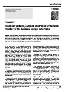
Quasi-Floating-Gate Transistor The equivalent circuit of the n-input N-type QFGMOS is shown in Figure 1. The input terminals are capacitively coupled to the quasi-floating gate (QFG) and its gate voltage (VQFG) is set to VDD through a pull-up resistor which can be implemented by using the large leakage resistance of the reverse biased p-n junction of a PMOS transistor operating in cut-off region.
Figure 1. Equivalent circuit of QFGMOS The quasi-floating gate voltage (VQFG) in Figure 1 can be expressed as sRleak CTotal VQFG Vin 1 sRleak C Total where
(1)
N ' CTotal C i C GS C GD C GB C GD
(2)
i 1
and Vin
1 N C iVi C GSVS C GDVD C GBVB C Total i 1
On substituting Equation (3) in Equation (1), VQFG becomes
(3)
18 Maejo Int. J. Sci. Technol. 2013, 7(01), 16-25 V QFG
1 C Total
N C i V i C GS V S C GD V D C GB V B i 1
sR leak C Total 1 sR leak C Total
(4)
We observe from Equation (4) that input signals encounter a high-pass filter with a cut-off 1 frequency of 2Rleak CTotal , which is very low due to large value of Rleak. Therefore, even for very low frequencies, Equation (4) becomes a weighted average of the AC input voltages determined by capacitance ratios plus some parasitic terms. The pull-up resistor Rleak sets a DC voltage equal to VDD on the quasi-floating gate upon which an AC voltage given in Equation (4) is superimposed. Hence, the gate voltage can become larger than VDD. Similarly for P-type QFGMOS, a pull-down resistor sets the DC gate voltage to VSS, which is implemented by a reverse biased p-n junction of an NMOS transistor in the cut-off region [10-18]. Voltage Controlled Resistor The circuit of a simple MOS-based VCR is shown in Figure 2 where MOSFETs M1 and M2 are biased in the triode region and M2 acts as resistor whose resistance can be controlled by its gate voltage (VC). The N-type current mirror formed by M3-M4 and P-type current mirror formed by M5-M6 ensure the same drain current in both M1 and M2. The transistors M1 and M2 are assumed to be perfectly matched transistors with the same drain currents I1 and I2 in the absence of input current (Iin) and M1 is biased in the ohmic region. This arrangement makes M2 operate in the ohmic region whose conductivity can be further varied by Iin. Thus, M2 acts as a variable resistor whose resistance value is controlled by VC [19]. V
DD
M5
M6
I4 I M4
3
M3
I in I I V
C
2
in
I
(for - ve resistence)
+
M2
V
M1
DS2
_
V SS
Figure 2. MOS-based VCR
1
19 Maejo Int. J. Sci. Technol. 2013, 7(01), 16-25 The equivalent resistance of the MOS-based VCR [3] is given by:
Req
VDS 2 1 I in K nVC
(5)
To ascertain the workability of the circuit shown in Figure 2, PSpice simulation was used by selecting W/L as 10μm/1μm for M1 and M2, 50μm/1μm for M3 and M4, 20μm/0.5μm for M5 and 40μm/1μm for M6 with a supply voltage of ± 0.75V. The simulated resistance (Req) varied with control voltage (VC) in accordance with Equation (5) as shown in Figure 3 where the resistance varies from 2 kΩ to 1.11 kΩ as control voltage varies from 0.3 V to 0.75 V. 300 Vc = 0.3V ; Req = 2 kΩ Vc = 0.45V ; Req = 1.59 kΩ Vc = 0.60V ; Req = 1.3 kΩ Vc = 0.75V ; Req = 1.11kΩ
250 200
VDS2 (mV)
150 100 50 0 -50 -100 -150 -200 -100
-80
-60
-40
-20
0
20
40
60
80
100
Input Current Iin (μA)
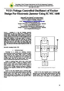
Figure 3. Resistance simulation using MOS-based VCR QFGMOS-based Voltage Controlled Resistor The QFGMOS-based VCR is shown in Figure 4. It differs from the FGMOS-based VCR presented [2] in that the gates of FGMOS are connected to a biased voltage through a large value capacitor (C2 >> C1) whereas the gates of QFGMOS are connected to the supply rails through reverse biased MOSFETs M8-M11. The drain currents of M1 and M2, biased in the ohmic region are given by: C 1 I 1 K n V SS C ' GD V DD C GS V SS C Total C Total C Total
V V Tn 1 DS 1 V DS 1 2
(6)
where Kn
0 C OX W L
and C V C' C I 2 I in I 4 K n 1 VC VSS GD VDD GS VSS VTn 2 DS 2 VDS 2 CTotal CTotal 2 CTotal
(7)
20 Maejo Int. J. Sci. Technol. 2013, 7(01), 16-25
V V
DD
SS
M9
M6
M5 V DD C
I
4
C
M8
V
V I
I
1
DD
in
I M 10
I
2
C
in
M 11
(for - ve resistence) +
M2 V V
3
M3
M4
DD
I
DS2
M1
_
C
C
V SS
Figure 4. QFGMOS-based VCR The current mirror arrangement of transistors M5 and M6 generates a current I3 such that I 3 I 4 I1 . Since transistors M3 and M4 are assumed to be perfectly matched and are biased in saturation region, their drain currents are given by: I3
Kn VGS 3 VTn3 2 2
(8)
I4
Kn VGS 4 VTn 4 2 2
(9)
which gives I in K n K 1VDD K 2VC VDS 2
(10)
From Equation (10), the equivalent resistance (Req) is given by:
Req
VDS 2 1 I in K n K 1VDD K 2VC
(11)
21 Maejo Int. J. Sci. Technol. 2013, 7(01), 16-25 where K 1
C ' GD C & K2 1 CTotal CTotal
(12)
Equation (11) reveals that the circuit in Figure 4 implements a VCR whose resistance value depends on the control voltage (VC). The corresponding equation for Req using FGMOS [2] is given by:
Req
1 K n K1Vb K 2VC
(13)
where K2 is the same as in Equation (11) for VCR using QFGMOS and K1
C2 . Since C2 >> CTotal
C'GD , the resistance value for QFGMOS-based VCR will be larger than FGMOS-based VCR at a given value of control voltage. It also results in a better frequency response of QFGMOS- based VCR than its FGMOS counterpart [8, 9]. RESULTS AND DISCUSSION
The circuit of Figure 4 was simulated using PSpice level 3 parameters with supply voltage of ± 0.75V and by selecting W/L of 10μm/1μm for M1 and M2, 50μm/1μm for M3 and M4, 20μm/0.5μm for M5, 40μm/1μm for M6 and 50μm/0.5μm for M8-M11. The variation of resistance with different control voltages is shown in Figure 5. It is observed that the value of the simulated resistance varies inversely with the control voltage as shown by Equation (11). 50 40 Vc = 0.3V ; Req = 1.48 kΩ Vc = 0.45V ; Req = 1.27 kΩ
30
VDS2 (mV)
20
Vc = 0.75V ; Req = 1.11 kΩ
10 0 -10 -20 -30 -40 -50 -30
-20
-10
0
10
20
30
Input Current Iin (μ A)
Figure 5. Resistance simulation with QFGMOS VCR The circuit of VCR was also implemented using FGMOS and its performance compared with its QFGMOS counterpart. The performance of QFGMOS-based VCR was found to be better than that of its FGMOS version due to the inherent advantages of QFGMOS over FGMOS. The values of the equivalent resistance realised using QFGMOS vis-a-vis FGMOS for different values of VC are given in Table 1. It can be seen that Req decreases from 1.48 kΩ to 1.11 kΩ for QFGMOS-based VCR and from 1.3 kΩ to 1.11 kΩ for FGMOS-based VCR with the increase in VC from 0.3 V to 0.75 V. A large value of the resistance of the order of kΩs or more can be obtained for smaller dimensions of transistors, which may lead to non-linearity.
22 Maejo Int. J. Sci. Technol. 2013, 7(01), 16-25 Table 1. Variation of Req with VC VC (V)
Req with QFGMOS (kΩ)
Req with FGMOS (kΩ)
0.3 0.45 0.6 0.75
1.48 1.27 1.19 1.11
1.30 1.23 1.17 1.11
It was also found that for control voltage (VC) of the order of supply voltage, both QFGMOS and FGMOS topology of VCR yield the same value of resistance. This can be attributed to the fact that Equations (11) and (13) approximately become identical and resemble Equation (5). when VC approaches positive supply voltage. The frequency response of QFGMOS-based VCR at different control voltages is shown in Figure 6. It can be observed that as control voltage increases from 0.3V to 0.75V, the bandwidth of QFGMOS-based VCR increases from 3.61 GHz to 4.9 GHz with the corresponding decrease in the value of simulated resistance. The same trend has also been observed in FGMOS-based VCR [2]. When control voltage in FGMOS-based VCR increases from 0.3V to 0.75V, the bandwidth increases from 490 MHz to 576 MHz and the corresponding value of simulated resistance decreases from 1.30 kΩ to 1.11 kΩ. This is due to the fact that with an increase in control voltage, the drain current of the transistors increases, which results in higher bandwidth and lower resistance. 64 VC = 0.3V
63
Req (dB ohm)
VC = 0.45V
62 VC = 0.6V
61 VC = 0.75V
60 59 58 10
100
1000
10000
Frequency (MHz)
Figure 6. Frequency response of QFGMOS-based VCR The comparative resistance simulation characteristics of VCR based on FGMOS and QFGMOS are shown in Figure 7. For the same value of control voltage (VC = 0.3 V), Req for FGMOS is 1.30 kΩ whereas it is 1.48 kΩ for QFGMOS-based VCR. The power dissipation of QFGMOS-based VCR (0.04 μW) is less than that of its FGMOS version (0.7 μW).
23 Maejo Int. J. Sci. Technol. 2013, 7(01), 16-25
VDS2 (mV)
50 40 30 20
VC = 0.3V FGMOS ; Req = 1.30 kΩ QFGMOS ; Req = 1.48 kΩ
10 0 -10 -20 -30 -40 -50 -30
-20
-10
0
10
20
30
Input Current Iin (μA)
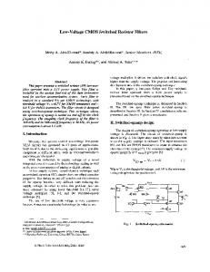
Figure 7. Comparative resistance simulation characteristics The comparative frequency response of QFGMOS- and FGMOS-based VCRs is shown in Figure 8. The bandwidth of QFGMOS-based VCR is found to be 3.61 GHz, which is greater than that of FGMOS based VCR (490 MHz) due to the absence of large capacitance (C2). 65 QFGMOS
Req (dB ohm)
63 FGMOS
61 B.W. of FGMOS = 490 MHz
59
B.W. of QFGMOS = 3.61 GHz
57 55 1
10
100
1000
10000
Frequency (MHz)
Figure 8. Comparative frequency response of QFGMOS- and FGMOS-based VCRs CONCLUSIONS
In this paper, we have briefly described QFGMOS and used it to implement a voltage controlled resistor (VCR). The characteristics of QFGMOS-based VCR were compared with those of its FGMOS counterpart. It was found that for a given value of controlling voltage, the QFGMOS-based VCR simulates a higher value of resistance and offers a larger bandwidth as compared to its FGMOS version due to its inherent advantages and consumption of less power. The PSpice simulation results were found to be in conformity with the theory.
24 Maejo Int. J. Sci. Technol. 2013, 7(01), 16-25 REFERENCES
1. 2. 3. 4. 5. 6. 7. 8. 9.
10.
11.
12. 13.
14.
15.
16.
I. L. S. Han and S. B. Park, “Voltage-controlled linear resistor by two MOS transistors and its application to active RC filter MOS integration”, Proc. IEEE, 1984, 72, 1655-1657. M. Gupta and R. Pandey, “FGMOS based voltage-controlled resistor and its applications”, Microelectron. J., 2010, 41, 25-32. W. Liu and S. I. Liu, “CMOS tunable 1/x circuit and its applications”, IEICE Trans. Fundam. Electron. Commun. Comput. Sci., 2003, E86-A, 1896-1899. W. Liu, S. I. Liu and S. K. Wei, “CMOS current-mode divider and its applications”, IEEE Trans. Circuits Syst. II, Express Briefs, 2005, 52, 145-148. E. Sanchez-Sinencio and A. G. Andreou, “Low Voltage/Low Power Integrated Circuits and Systems: Low-Voltage Mixed-Signal Circuits”, Wiley-IEEE Press, New York, 1999, p. 562. S. Yan and E. Sanchez-Sinencio, “Low voltage analog circuit design techniques: A tutorial”, IEICE Trans. Analog Integr. Circuits Syst., 2000, E00-A, 179-196. J. Ramirez-Angulo, S. C. Choi and G. G. Altamirano, “Low-voltage circuits building blocks using multiple-input floating-gate transistors”, IEEE Trans. Circuits Syst. I, 1995, 42, 971-974. S. Sharma, S. S. Rajput, L. K. Mangotra and S. S. Jamuar, “FGMOS current mirror: Behaviour and bandwidth enhancement”, Analog Integr. Circuits Signal Process., 2006, 46, 281-286. J. Ramirez-Angulo, C. A. Urquidi, R. Gonzalez-Carvajal, A. Torralba and A. Lopez-Martin, “A new family of very low-voltage analog circuits based on quasi-floating-gate transistors”, IEEE Trans. Circuits Syst. II, 2003, 50, 214-220. J. Ramirez-Angulo, A. J. Lopez-Martin, R. G. Carvajal and F. M. Chavero, “Very low-voltage analog signal processing based on quasi-floating-gate transistors”, IEEE J. Solid State Circuits, 2004, 39, 434-442. C. Urquidi, J. Ramirez-Angulo, R Gonzalez-Carvajal and A. Torralba, “A new family of lowvoltage circuits based on quasi-floating-gate transistors”, The 2002 45th Midwest Symposium on Circuits and Systems, 2002, Tulsa, USA, Vol.2, pp.93-96. I. Seo and R. M. Fox, “Comparison of quasi-/ pseudo-floating gate techniques and low-voltage applications”, Analog Integr. Circuits Signal Process., 2006, 47, 183-192. K. A. Townsend, J. W. Haslett and K. Ineiwski, “Design and optimization of low-voltage lowpower quasi-floating gate digital circuits”, Proceedings of 5th International Workshop on Systemon-Chip for Real-Time Applications, 2005, Washington, DC, USA, pp.132-136. L. Ren, Z. Zhu and Y. Yang, “Design of ultra-low voltage op amp based on quasi-floating gate transistors”, Proceedings of 7th International Conference on Solid-State and Integrated Circuits Technology, 2004, Beijing, China, Vol.2, pp.1465-1468. J. Alfredsson and B. Oelmann, “Influence of refresh circuits connected to low power digital quasifloating gate designs”, Proceedings of 13th IEEE International Conference on Electronics, Circuits and Systems, 2006, Nice, France, pp.1296-1299. A. Torralba, J. Galan, C. Lujan-Martinez, R. G. Carvajal, J. Ramirez-Angulo and A. Lopez-Martin, “Comparison of programmable linear resistors based on quasi-floating gate MOSFETs”, Proceedings of IEEE International Symposium on Circuits and Systems, 2008, Washington, USA , pp.1712-1715.
25 Maejo Int. J. Sci. Technol. 2013, 7(01), 16-25 17. A. Torralba, C. Lujan-Martinez, R. G. Carvajal, J. Galan, M. Pennisi, J. Ramirez-Angulo and A. Lopez-Martin, “Tunable linear MOS resistors using quasi-floating-gate techniques”, IEEE Trans. Circuit Syst.-II: Express Briefs, 2009, 56, 41-45. 18. R. Gupta, S. Sharma and S. S. Jamuar, “A low voltage current mirror based on quasi-floating gate MOSFETs”, Proceedings of IEEE Asia Pacific Conference on Circuits and Systems, 2010, Kuala Lumpur, Malaysia, pp.580-583. 19. H. Barthelemy, S. Meillere and E. Kussener, “CMOS sinusoidal oscillator based on currentcontrolled current conveyors”, Electron. Lett., 2002, 38, 1254-1256.
© 2013 by Maejo University, San Sai, Chiang Mai, 50290 Thailand. Reproduction is permitted for noncommercial purposes.