con icts, and it may be di cult to convey to the users ... ning e ect is used in the tug of war e ect to supply ... Objects can be either pulled (as in Figure 3) or.
Warping Distributed System Con gurations � Bruce Thomas David Stotts and Lalit Kumar School of Computer and Information Science Computer Science Dept. Univ. of South Australia Univ. of North Carolina, Chapel Hill
Abstract
single user system.1 Consequently, techniques for conveying these subtle interface cues are largely absent from the literature. Our current approach to conveying subtle user interaction cues is to visibly animate the 3D objects in di�erent ways as the users a�ect them. The animation method we are currently studying is real-time shape warping [18, 17]. We have built a prototype system called MUVEE (multi-user virtual environment editor) to embody these warping operations for experimentation. MUVEE is a multi-user distributed system that allows several di�erent people to create and modify 3D objects in a shared virtual space. The objects are warped as users grasp, move, scale, and rotate them. In the following sections we rst report on related work. After that, we explain the structure of MUVEE and the warping operations we have created in it. Following that we describe an application using MUVEE and object warping: a 3D visualization environment for examining and "tweaking" the con guration of a distributed system.
We have developed interface animation techniques for distributed collaborative 3D virtual environments. Our methods communicate information about group interactions to the various individual users in the system; this information is traditionally absent (i.e., not needed) from single user systems and is di�cult to convey with static interfaces. Interface animation is primarily accomplished by dynamically warping the shape of the objects in the virtual space. We describe our warping methods and a system call MUVEE in which we have embedded them. We also describe an application of these ideas for con guring distributed systems in general: visualizing the con guration and performance of a distributed system as a warpable virtual environment. We have implemented our experimental prototypes with the Polylith toolbus [12].
1 The problem and the approach
2 Related Work
Collaborative virtual environments are multi-user distributed systems in which several users share a 3D virtual space. The interactions among users may cause con icts, and it may be di�cult to convey to the users involved exactly what the con icts are. For example, in a 3D environment where users can grasp and move objects, if two users grasp the same object simultaneously the system must decide what should happen. Should one user be given the object and the other denied? Should both be denied and the object frozen until one lets go? If the object is frozen in place, how will the users know that the system has not simply failed? This kind of information arises from subtle interactions, so does not have to be communicated in a
Projects directly related to our work are scarce. Some work has been done on visualization of process networks, but our 3D VE approach is unique as far as we can determine. In addition to Polylith [12], on which we have built MUVEE, there are numerous other projects that have investigated speci cation languages and support systems for constructing distributed networks of processes [1, 7, 6, 8, 10, 11, 14, 3]. 1 We should note that these problems arise whether or not the VE users have avatars (visible representations; in most current VEs, avatars are very simple, unarticulated forms, so a user may see in a gross way the presence of another user near an object, but will not see a moving or pinching hand to indicate grasping.
� This work is supported in part by grants from the O�ce of Naval Research and DARPA.
1
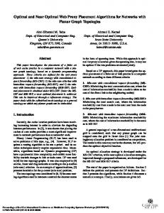
Figure 1. 3D space rendered in MUVEE
The process migration and dynamic recon guration we plan to experiment with, once the full Polylith/MUVEE interface is complete, will be based on Purtilo's more recent packager research. Several projects have explored distributed (and collaborative) virtual environments in general [9, 19, 13, 2, 4, 5], but none have applied VE modeling and manipulations to the con gurability of distributed systems themselves. These projects are mostly stand-alone systems that have explored basic DVE concepts of object model interchange, networking performance, and underlying application-level protocols.
ously grasp an object, leading to the need for communicating information about con icting interactions. We approach this and other problems by warping the 3D objects in di�erent ways. The 3D warping e�ects have been implemented as a new warping Inventor shape node [16]. This section presents window-based animation effects of four direct manipulation operations: translation, scaling, rotation, and pinning. Finally, the pinning e�ect is used in the tug of war e�ect to supply additional information for two users interacting with the same object.2 Figure 1 show the MUVEE viewing screen, with 4 cubes displayed. This is the view one user would have. Other users would have di�erent views of the space, depending on eyepoint and direction of view.
3 Object warping in MUVEE MUVEE is a multi-user distributed virtual environment, built with the Inventor [15] graphics toolkit. It is functionally quite simple, having been constructed to experiment with the user-interface concept of object warping for conveying subtle interaction information. Users of MUVEE are able to instantiate several basic shapes (sphere, cone, square), move them around in 3-space, scale and rotate objects, and delete objects. The space is shared, meaning several users are able to do this concurrently. Two users are able to simultane-
3.1
Translation
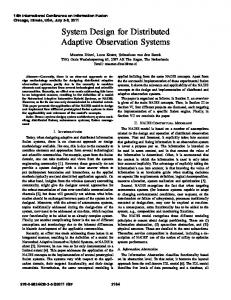
Figure 2 shows a 3D direct manipulation move operation on a cube. The gure shows the move operation with animation, where the one vertex of the cube stays attached to the mouse point while the bulk of 2 While our discussion here in in the context of a 3D application, our warping concepts are useful in 2D worlds as well.
2
Figure 2. Animating a move operation with 3D graphical objects Figure 4. Pushed In Center
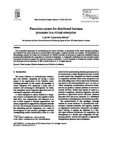
Figure 3. Pulled Out Center
the object lags slightly behind. This animation gives the e�ect of manipulating a heavy \rubbery" object that distorts as it is pushed and pulled. Although the e�ect does not correspond exactly to a physical model, this simple algorithm gives the impression that the shape is made of elastic material, with weights attached to the vertices, causing them to lag behind the movement. The gures used in this paper for depicting the 3D animation e�ects have a wire frame drawing of the e�ect in their left diagram and a solid rendered drawing in their right diagram. The two diagrams in the gures are identical graphical models; they have just been rendered with two di�erent techniques. The grasped point, however, need not be a vertex, but in fact may be any point on the surface of the object. Objects can be either pulled (as in Figure 3) or pushed (as in Figure 4); when mouse movement stops, the lagging portions of the moving object "catch up" with the grasped point and the object "snaps back" to its unwarped shape. 3.2
Scaling and Rotating
The animation e�ects described above for translation are also e�ective when used in conjunction with other common direct manipulation operations. For example, Figure 5 illustrates a 3D operation to make an object smaller by scaling. As in the translation exam-
Figure 5. Animated 3D Scale Down Effect
3
shown in Figure 7. This gure shows an animation effect that avoids both problems. As the user attempts to drag the pinned object, the grasped point stays attached to the mouse but the bulk of the object stays xed. The e�ect is as if the user is pulling on a corner of an object that is anchored in place. The feedback provides extra information: it makes it clear that the user is attempting to move the object, but that the attempt is not succeeding. When the grasped point is released, the object springs back to its original shape.
Figure 6. Animating a 3D Rotate Effect
3.4
Collaborative systems are required to provide visual cues when multiple users are simultaneously manipulating a particular data object. The tug-of-war e�ect shown in Figure 8 depicts a form of visual feedback when two users are attempting to move an object simultaneously. The object is rst moved by one user. Once the object has been grasped by a second user, the object stops moving. While the two users attempt to move the object, the grasped corners of the object are stretched out demonstrating that no one user has full control of the object.
Figure 7. 3D Pin Effect
ple, during the animated version of the scale operation the part of the object that is \grasped" is controlled by the user, while the bulk of the object lags behind. An animation e�ect pulls out the ungrasped vertices of the cube (or, really, pulls in the sides while the vertices lag). A complementary animation e�ect is used in 3D scaling to make an object larger. Figure 6 shows a 3D operation to rotate an object about its center. Once again the animation e�ect is to have the object lag behind so as to give the illusion that the object has inertia. 3.3
Tug of War
4 The MUVEE multi-user interaction protocol Each user in MUVEE is running a copy of the program, so all users are executing identical code. The world is virtually shared by having each user maintain a local copy of the world. Messages are exchanged to allow each user to keep current on the locations and activities of the others. Our primary concern in this protocol is to ensure consistency across users in the state of each local world. To better delineate the messages that need to be exchanged, we will subdivide the transformations (move,rotate, and scale) into three distinct phases:
Pinning
The pinning animation is used to supply simple visual constraining e�ects which can convey extra information for direct manipulation operations. Consider an attempt to move an object that is xed in place { i.e. pinned. One response to this attempt might simply be to prevent the object from following the mouse. However, this lack of visible feedback might be misinterpreted as the result of a failure to \grasp" the object correctly. A user might make several attempts at the operation before realising the true cause of the lack of response. Another strategy might be to allow the object to follow the mouse, but then to snap it back to its original place when released. This approach avoids the problem with lack of feedback, but can lead to surprises when a carefully placed object suddenly jumps back to a previous position. A single frame of a 3D pinning animation e�ect is
� � �
grasp (mouse down) transformation (mouse move) release (mouse up)
This division is needed due to the possibility of multiple users trying to move one object concurrently. The "grasp" operation will sometimes cause the object to be pinned (if another user has earlier grasped it), and at other times will not. Grasp Operation
4
Figure 8. Tug of War Effect
the mouse.
The grasp operation allows users to gain control of a graphical object in the application. This operation also signals to the other users the object is under the control of this users. As previously mentioned, the application may use a pinning visual e�ect to indicate more than one user has grasped the object.
Create Operation The create operation allows users to add a new
graphical object to the application. This operation is an atomic operation in the current system. The user issues a create command and the new graphical object is instantiated on all the distributed applications. This graphical object is placed at some known position, for example the origin of the drawing space. If two users create a graphical object at the same time, two graphical objects of the same type would be created. A second approach to this operation is once the object is created, the system goes into a grasp phase. Once in the grasped phase, other users can simultaneously interact with the object.
Release Operation The release operation informs all other users that
this user an relinquished control of a graphical object in the application. The application, once receiving a release command, may alter the visual feedback of an operation. For example, the graphical object may no longer be pinned. Move Operation The move operation allows users to translate a
graphical object in the application. The amount of movement is determined from the user's movement of the mouse.
�
create (mouse down) grasp (after object is created)
�
translate (mouse move)
�
release (mouse up)
�
Rotate Operation The rotate operation allows the user to change the
orientation of a graphical object by movement of the mouse.
Delete Operation The delete operation allows users to remove an exist-
Scale Operation
ing graphical object to the application. This operation has the three distinct phases:
Similarly, the scale operation allows the user to change the size of a graphical object by movement of 5
�
grasp (mouse down)
�
delete (mouse continues to be down)
�
release (mouse up)
5.1
Performance control via warping
MUVEE presents a snapshot to a user of the con guration and performance of an executing distributed system. However, we can use the same tool to inject con guration and performance control information back into a system, again via warping. Rather than simply viewing the objects in the MUVEE world, we allow the user to manipulate them as well. Consider an object in the MUVEE world that is warped; the warped shape will be pointing in the direction of the process that is generating the tra�c. One object may even be warped in several directions (like in the tug-of-war operation above), indicating that it is receiving surplus tra�c from several di�erent processes. Let's call the warped object (representing the slow process) S, and call the tra�c-generating object T. The user can grasp the T object and drag it back towards the S object. This will visually warp T somewhat, and it will also send a message to the T process to slow down. The resulting drop in tra�c to the S process will cause the S object to lose some warp as it catches up. The more the user warps T, the more it will slow down. Releasing the T object will cause the T process to resume normal performance. One observes this interesting visual phenomenon: In a certain con guration, the performance of a system of processes causes a rather distorted overall picture, with several warped objects. By further warping some of the normal objects manually, the warped ones will "settle down" and return to a less stressed form. Di�erent warping operations are used for di�erent performance adjustments to the processes. We have already indicated that the pinned warp is used to selectively cut the message transmission rate to one speci c process (the one in the direction of the warp). The scaling warp is more general; it will speed up or slow down a process uniformly (i.e., cut the message transmission rate to all other processes).
This enables the system to provide visual feedback if more than one user has grasped an object, and the result of this delete operation. An application can then provide visual cues as to its deletion policy. For example if an object can not be deleted if it is grasped by more than one user, the application may animate it shrinking and leave a transparent copy for the other users to manipulate.
5 Application: Warp-based visualization of con gurations In this section we describe a novel application for visualizing and "tweaking" the con guration of a distributed system, using the warping e�ects we have embodied in MUVEE.3 When a distributed system is generated from our modi ed Polylith system, we create a MUVEE world (VE) representing several physical aspects of the system con guration. The objects in the VE have different shapes and colors to indicate di�erent process properties, and they are arranged spatially to show the network connections set up among the processes. As the process network executes, as tra�c patterns change, as the processes become "loaded", performance will change. As a process is loaded to the point where it is "falling behind" its collaborators, MUVEE starts to warp its corresponding object in the shared VE space. The more warped an object becomes, the more extreme is its execution status with respect to "normal." This loading might come from a slow host being unable to
ush a message bu�er as fast as the senders ll it, for example. The 3D interactive VE gives users a quick, holistic picture of the entire system. A nicely behaving system will look mostly unwarped. Temporary performance variability will be expressed by minor warping that appears and disappears over time. When a system develops more serious trouble the warping will become more pronounced, more long-lived, perhaps even more widespread, a�ecting more objects as trouble in some processes begin to create chain-reaction problems in other processes.
5.2
Other interpretations for warp operations
As our experiments progress, we will explore numerous ways to map warp operations onto con gurations and performance characteristics. Here are some other possibilities. One source of the loading we seek to visualize and control is a shortage of resources on the host platform for a process. For example, a shortage of CPU, memory, or disk I/O could all be possible sources of performance problems. The users on the other systems are not concerned with why there is a slow down, but only
3 Our implementation is still progressing but should be complete in time for the conference.
6
that there is a slow down. A warping visual e�ect by rotation or scaling may be employed to highlight this fact. A rotation e�ect could show the following: �
�
�
back. The instrumented bus keeps track of state information such as message queue length, relative speeds, etc., and communicates this to MUVEE for rendering via the appropriate object warps. Information also ows from MUVEE back to the bus. Messages to slow down or speed up a process will cause the bus to alter the governor settings on the message queues.
A graphical object representing a process which has no shortage of resources would be displayed without rotation. A graphical object representing a process which has a shortage of resources greater than a prede ned value would be displayed 45 degree in a clockwise rotation. A graphical object representing a process which has a shortage of resources less than a prede ned value would be displayed as that fraction of 45 degrees in a clockwise rotation.
5.4
One other warping feature of MUVEE is intriguing for applying to dynamic recon guration (rather than performance). In MUVEE, when an object is pinned by one user, if another grasps it and moves it the tug-of-war stretching happens. If one of the users is persistent in this tug-ofwar and warps the object sharply it will "snap in two", essentially causing an object copy. The motion that causes this split is either a fast, snapping mouse motion, or a long stretch past a virtual "breaking point." These snap-warps seem appropriate as a manual way to signal system recon gurations of di�erent kinds. Pulling an object into two could be a signal for process replication. Manual movement of the new object copy could be used to designate the new host. A host that is already overloaded could signal the inappropriateness of a suggested migration by "pushing back" on the object, visually warping it as the user moved it close.
Scaling operations could show the following: �
�
�
A graphical object representing a process which has no shortage of resources would be displayed without scaling. A graphical object representing a process which has a shortage of resources greater than a prede ned value would be displayed scaled by 50%. A graphical object representing a process which has a shortage of resources less than a prede ned value would be displayed as that fraction of a 50% scaling.
6 Conclusion
The previous Figure 6 shows a 3D version of the rotation e�ect on an object representing a process in a CDS. Previous Figure 5 shows a 3D scaling e�ect on a process object. In each case, the inertia and the "rubbery" appearance of the object convey the impression that the process is under some strain. 5.3
Reconfiguration via warping
The paper presented the results, to date, in our investigation of the use of warping animation e�ects to depict and a�ect system con guration information. Four warping e�ects were presented: translation, rotation, scaling, and pinning. The pinning e�ect was extended to produce a "tug of war" e�ect to highlight multiple users simultaneously manipulatinga single object. A multi-user distributed system (MUVEE) has been developed to experiment with these e�ects; MUVEE allows several di�erent people to operate a 3D graphical editor in a shared virtual space. Finally, a set of warp-based visualizations of con guration information was presented. A second application area that we are exploring is somewhat di�erent from the visualization methods we have outlined. Again using Polylith, we are generating distributed VEs that allow warping of objects as an interface option. We have modi ed the Polylith specs format to allow a process to be designated as a warper, a nonwarper, or a selective warper.
Mechanisms
Visualization and performance control of a CDS through MUVEE warping is accomplished by instrumenting the Polylith toolbus. When a CDS is generated by the bus, the normal message queues are generated with extra instrumentation allowing measurement and communication of performance information between the bus and the processes. We also have to add a speed control capability to the message queues generated and maintained by the Polylith bus. MUVEE becomes one more process in the network, and information ows from the bus to MUVEE and 7
In selective warping, when appropriate (based on system/network performance) a process will do warping operations in its interface. However, a slower process that is doing selective warping may opt to stop and use static object representations if its performance relative to the remainder of the network is lagging, or if its host is computationally unable to provide such complex graphics in real-time. Our reasoning is that one machine should not slow the whole team down just for the luxury of having an animated interface.
[10] J. Magee, J. Kramer, and M. Sloman. Constructing distributed systems in conic. IEEE Transactions on Software Engineering, 15:663{675, June 1989. [11] D. Notkin, A. Black, and E. Lazowska et al. Interconnecting heterogeneous computer systems. Comm. of the ACM, 31:258{273, 1988. [12] J. Purtilo. The polylith software bus. ACM Trans. of Programming Languages ansd Systems, pages 151{174, January 1994. [13] G. Singh, L. Serra, W. Png, A. Wong, and H. Ng. Bricknet: Sharing object behaviors on the net. In Proc. of VRAIS '95, pages 19{25, 1995. [14] R. Snodgrass. The Interface Description Language: De nition and Use. Computer Science Press, 1989. [15] P. S. Strauss. Iris inventor, a 3d graphics toolkit. In OOPSLA '93, pages 192{200, Washington D.C., October 1993. ACM, ACM Press. [16] B. H. Thomas. 3d warping transformation. Technical report, School of Computer and Information Science, University of South Australia, 1997. [17] B. H. Thomas. 3d warping visual feedback for multimedia and virtual reality. In Proc. of the Int'l.
References [1] M. Barbacci, D. Doubleday, C. Weinstock, and J. Wing. Developing applications for heterogeneous machine networks: The durra environment. Computing Systems, 2:7{35, 1989. [2] C. Carlsson and O. Hagsand. Dive { a platform for multi-user virtual environments. Computers and Graphics, pages 663{669, 1993. [3] J. Wileden et al. Speci cation-level interoperability. Comm. of the ACM, 34:72{87, May 1991. [4] T. A. Funkhouser. Ring: A client-server system for multi-user virtual environments. In Computer Graphics (1995 SIGGRAPH Symposium on Interactive 3D Graphics), pages 85{92, April 1995.
Conf. on Computational Intelligence and Multimedia Applications, page in press, Feb. 9-11 1998.
[5] T. A. Funkhouser. Network topologies for scalable multi-user virtual environments. In Proc. of IEEE VRAIS '96. IEEE, April 1996. [6] N. Habermann and D. Notkin. Gandalf: Software development environments. IEEE Transactions on Software Engineering, 12(12):1117{1127, December 1986. [7] R. Hayes, S. Manweiler, and R. Schlichting. A simple system for constructing distributed, mixedlanguage programs. Software Practice and Experience, 18:641{600, July 1988. [8] M. Jones, R. Rashid, and M. Thompson. Matchmaker: An interface speci cation language for distributed processing. In Proc. of the 12th POPL Conference, 1985. [9] M. R. Macedonia, M. J. Zyda, D. R. Pratt, D. P. Brutzman, and P. T. Barham. Exploiting reality with multicast groups: A network architecture for large-scale virtual environments. In Proc. of VRAIS '95, pages 2{10, 1995.
[18] B. H. Thomas and P. R. Calder. Animating direct manipulation interfaces. In Proceedings of UIST'95: ACM, pages 3{12, Pittsburgh, November 1995. [19] Q. Wang, M. Green, and C. Shaw. EM{an environment manager for building networked virtual environments. In Proc. of VRAIS '95, pages 11{ 18, 1995.
8