Dec 6, 1986 - Abstract-This paper introduces a new adaptive microphone-array system for noise reduction (AMNOR system). It is first shown that there.
IEEE TRANSACTIONS ON ACOUSTICS, SPEECH,
AND SIGNAL
PROCESSING, VOL. ASSP-34, NO.
6 , DECEMBER 1986
1391
Adaptive Microphone-Array System for Noise Reduction Abstract-This paper introduces a new adaptive microphone-array and applied in other fields such as antenna, sonar, and system for noise reduction(AMNOR system). It isfirst shown that there seismic focus searching. These techniques, called ‘ ‘adapexists a tradeoff relationship between reducing the output noise power tive arrays,” achieve effective rejection of unwanted sigand reducing the frequency response degradation of a microphone-array to a desired signal. It is then shown that this tradeoff can be con- nals with asmall number of sensorelements. Various methods [3]-[6] have been presented, eachbased on some trolled by the introduction of a fictitious desired signal. A new optimization criterion is presented which minimizes the output noise power optimization criterion, such as maximizing the SNR or while maintaining the frequency response degradation below some preminimizing the mean-square error. Although the majority determined value(AMNOR criterion). AMNOR determines an optimal of these conventional applications have focused on a narnoise reductionfilter based on this criterionby controlling thetradeoff utilizing the fictitious desired signal. Experiments on noise reduction row frequency range [7], an adaptivearraytechnique processing were carried out in a room with 0.4-s a reverberation time. based on the LMS criterion proposed by Widrow et al. The superiority of the AMNOR criterion over conventional LMS and, [3], and a technique based on the constrained LMS criconstrained LMS criteria for reducing noise in speech signals was con- terion proposed by Frost [6], have been proposed for wide firmed in subjective preference tests. The AMNOR system improved frequency range signals. However, there exist some difthe SNR by more than 15 dB in the 300-3200 Hz range.
I. INTRODUCTION NEW smallsize microphone-array system called “AMNOR”(adaptive microphone-array for noise reduction) is presented. The AMNOR system uses a new optimization criterion to realize an effective noise reduction system for a wide audiofrequency .range. When a microphone is used to receive a desired audio signal (such as human speech), ambient noise from other sources often interferes with the desired signal. Two conventional approaches have been used to solve this problem. One is a “speech enhancement” signal processing technique, which utilizes differences in the statistical characteristics of speech andnoise. Although various methods based on this approach have been tried [ 11, they sometimes result in nonlinear distortion of the speech signal. The other approach utilizes differences in the arrival directions of the .desired signal and the noise. The wellknown “directional microphone” is a familiar example. However, the mainlobe of the directional pattern is not satisfactorily sharp. To sharpen this lobe, delay-and-sumtype microphone-arrays have been employed [2]. However, an array as long as l m or more is needed to realize a sharp lobe in the low-frequency range. On the other hand, techniques which utilize arrays in conjunction with signal processing have been developed
A
Manuscript received April 22, 1985; revised April 30, 1986. Y.Kaneda is with the Electrica.1 Communication Laboratories, Nippon Telegraph and Telephone Corporation, 3-9-11 Midori-cho, Musashino-shi, Tokyo, 180 Japan. J. Ohga is with the Customer Premises Equipment Division, Fujitsu Limited, 629, Shimokodanaka, Nakahara-ku, Kawasaki, 211 Japan. IEEE Log Number 8610393.
ficulties, stated in the following section, which become apparent when these conventional techniques are applied to the noise reduction problem in speech signals. In this paper, a new adaptive array signal processing technique is proposed for a wide frequency range audio signal based on a new optimization criterion (AMNOR criterion).Theconcept of the AMNOR criterionis to minimize the output noise power, while maintaining the degradation in the frequency response to the desired signal below some permissible value. In Section 11, the noise reduction problem is formulated using amicrophone-array, and theconventionaltechniques are discussed. In Section 111, the AMNOR criterion is introduced, and a new algorithm for deriving the optimal noise reduction filter based on the criterionis presented. In Section IV, the superiority of the AMNOR criterion over the conventional criteria for thespeech signal noise reduction problem is demonstrated experimentally. Results of noise reduction experiments conducted in a conventional room are also presented in this section. 11. PROBLEM FORMULATION AND CONVENTIONAL OPTIMIZATION CRITERIA The noise reduction problem is first formulated using a microphone-array . The microphone-array and noise reduction filtering scheme is shown in Fig. 1. In this paper, all acoustical and electrical signals are regarded as discrete signals; therefore, z-transforms are used for the frequency domain expressions. In Fig. 1 , Gi(z), i = 1, 2, . . . , M (where M is the number of microphone-array elements), represent acoustical transfer functions from the desired sigrial sourceto each microphone element. All noise sounds are assumed to be stationary and ergodic.
0096-3518/86/1200-1391$01.00 O 1986 IEEE
1392
IEEE TRANSACTIONS
I I
5-JMicrophone-
Noise reduction
array
filtering
Fig. 1. Microphone-array and noise reduction filtering.
Hl represents an M-input single-output noise reduction filter. H1includes M number of single-input single-output FIR filters Hi’ (z), i = 1, 2, * - , M . Received signals, ui(n>’s,i = 1, 2 , * , M , are filtered by H; (z)’s and are summed up in H , to produce an output signal y (n).Noise components in the received signals are reduced in the filter Hl . The determination of the filter coefficients is therefore critical and is the major areaof concern in this paper. In conventional adaptive array techniques for wide frequency range signals, two kinds of optimization criteria are used for the determinationof the noise reduction filter coefficients. One is the least-mean-square (LMS) criterion [3] and the otheris Frost’s constrained LMS criterion 161. An optimal filter based on the LMS criterion minimizes the mean-square error between a reference signal which is highly correlated to the desired signal and an output signal. However, in practice,it is difficult to generate such a reference signal. According tothemodel in Fig. 1, the frequency response F ( z ) of this microphone-array system to the desired signal can be expressed as M
F(z) =
i= 1
Hi (z) Gj(2).
VOL. ASSP-34, NO. 6, DECEMBER 1986
ON ACOUSTICS, SPEECH, AND SIGNAL PROCESSING,
response characteristics of the human auditory system must be taken into account in formulating the optimization criterion for AMNOR processing. Significant degradation in the desired signal is unacceptable, although the noise level may be greatly reduced. This occurs when the unconstrained LMS criterion is used. However, some degradation can be tolerated by the human auditory system [8]. This implies that Frost’s constraint is too rigid. Consequently, a new optimization criterion is proposed in which it isdesirable to attain maximum noise reduction while allowing a small degree of degradation in the frequency response to the desired signal. Based on the new criterion, AMNOR performs a kind of constraint minimization. In contrast with Frost’s constraint which permits only one specified F ( z ) , AMNOR adopts a soft constraint which permits a class of F(z)’s whose degradation is less than some permissible value. This difference in constraint allows for more freedom in the choice of the filter coefficients of Hi (z)’s, and hence, offers promise of further noise reduction performance. In Section 111-B which follows,a measure Dl which reflects the amount of degradation in F ( z ) is first proposed. Then a signal called a fictitious desired signal (FD signal) is introduced and thecharacteristics of unconstrained adaptive filtering are studied. It will be shown that there exists a tradeoff relationship between reducing the degradation in F ( z ) and reducing noise power, and this relationship can be controlled by the FD signal level. In Section 111-C, the FD signal level adaptation method for deriving the optimal filter based on the AMNOR criterion is presented. In Section 111-D, the overall signal processing scheme for realizing the adaptive process stated in Section 111-C is presented.
B. Controllability of the Tradeoff Relationship Between (1) Response Degradation and Output Noise Power
When the LMS criterion is used, it sometimes happens that the frequency response F ( z ) is greatly degraded resulting in severe distortion of the desired signal. This degradation is a function of the SNR of the received signal. An optimal filter based on Frost’s constrained LMS criterion minimizes the output noise power while constraining the response F ( z ) to be a,uniquely predetermined desired frequency response. A typical constraint is one that forces the array to have a flat response over the entire frequency range ( I F(ejwT”) I = 1, for all w , where To is the sampling period). In this paper, this is referred to as a distortionless constraint. However, due to the rigidity of this constraint for the frequency response, the improvement in the SNR is generally not satisfactory.
The quantity Dl is first defined in the following equation:
-
rdTo
where
To : sampling period, 7 : constant.
This quantity D , is the frequency average for the squared deviation of F ( z ) ( z = e j w T , from the nondegraded response of the unit gain magnitude and linear phase shift. Therefore, this quantity Dl represents the degree of degradation of the frequency response to the desired signal F ( z ) . Hereafter, D l will be referred to as “response degrada111. AMNOR SIGNALPROCESSING tion.” A. Concept of AMNOR Optimization Criterion Two requirements are then introduced for AMNOR sigThe objective in this paper is to develop a noise reduc- nal processing. Requirement I : Transfer functions Gi(z), i = 1 , 2 , * * , tion array system for speech signals, the output of which is acceptable to the human ear. Therefore, the nature and. M , are known.
-
KANEDAANDOHGA:ADAPTIVE
1393
MICROPHONE-ARRAY SYSTEM
If the desired signal is regarded as aplane wave, transfer functions Gj(2)’s are then pure delays. By disregarding the common puredelay component in each function, Gi( z ) can then be calculated from the array geometry and the arrival direction of the desired signal. In this case, requirement 1 can be rewritten as follows. Requirement 1: The arrival direction of the desired signal is known. Requirement 2: Signals uNi(n), i = 1, 2, * * , M , which do not contain the desired signal but only noise to be suppressed, can be received at certain time intervals. An example of such a time is the period immediately before the onset of the desired speech signal. Requirement 2 is discussed in more detail in Section V-C. Now, consider the block diagram shown in Fig. 2. First, it is necessary to introduce a signal called a fictitious desired signal (FD signal). This is expressed as A * s’ (n), where A represents a positive constant value, hereafter referred to as the FD signal level. s’ (n) is white noise with a power of 1, that is, 1 s’(n)l2 = 1, where the overbar denotes the time averaging. The FD signal is applied to M filters, which have transfer functions G I(2) to GM(z). Only noise signals are assumed to be received by the microphone elements at this time. The received noise signals, uNi(n), i =: 1, 2, * , M , are added to the filtered FD signals, and M signals uf(n), i = 1 , 2, , M ,are derived. Next, each ui(n) is filtered by H:(z); and the outputs are summed to generate signal y’(n). Then, y ‘ ( n ) is subtracted from the delayed FD signal A s‘ (n - 7,) ,and an error signal e ( n ) is derived. Here, r, is a delay time which makes it possible to seek an optimal filter from among the filters which are noncausal when the delay 7, is not used. Assuming that there is no correlalion between the, FD signal and the received noise signals, the mean-square of error signal e ( n ) can be given by
I
-
-
I
F D signal generator
-
--
9
I
Fig. 2. Introduction of fictitious desired (FD) signal. M
A2
/s‘(n -
.
7,)
-
c hi(n) 0 g ( n ) 0 s’(n)
i=l
1
2
M e-jw7~
-
2 H!(ej& I
i= 1
) Gi(ejw“) dw,
(4)
where 1 S’ (ejwT”) l2 is the power spectrum of s‘(n), which is “ 1 . ” According to (1) and (2), (4)represents the form of the response degradation of (2). Also, the output noise power denoted as D2 can be calculated by the.fol1owing equation: D2 =
I cM
hi(n) 0 U N j ( r l )
I .
(5) Then, using (2), (4),and ( 5 ) , the mean-square error (3) can be expressed as a linear combination of response degradation D l and output noise power D2. i=l
+D~. (6) Here, a K-dimensional (where K = M - (L + 1)) filter
I2
(e(n) =
*
coefficient vector h is defined as
where
2, * , L): filter coefficients (or impulse response) of the Lth-order FIR filter
hi(n)( n
= 0, 1,
Hi (4, gi.(n):impulse response of G i ( z ) ,and 0: convolution.
Hereafter, the filter coefficient vector h will be referred to simply as “FCV.” This FCV completely specifies the Applying the Wiener-Khintchine theorem, thefirst term characteristics of the noise reduction filter and therefore of (3) can be expressed as those of the entire microphone-array system.
1394
VOL. ASSP-34, NO. 6, DECEMBER 1986
ON ACOUSTICS, SPEECH, AND SIGNAL PROCESSING,
IEEE TRANSACTIONS
TheFCV which minimizes this mean-square error is a function of the FD signal level A . Therefore, this FCV is denoted as h ( A ) . h ( A ) can be calculated by the following equation as shown in [ 3 ] .
Initialvalue of FD signal level A
I e(n),1
h(A)
=
R-’
A
*
s’(n -
7,)
ur(n),
(8)
where
u’(n) = [u;(n),u;(n- l j , u,Xn -
-
*
*
,u;(n - L),u;(n), * . * ,
R = u’(n) u r ( n l T . When the FCV h (A) is used for the noise reduction filter in the microphone-array system, the response degradation for the system at that time is expressed as Dl(A) and the output noise power of the system is expressed as D,(A) [actually both Dl(A) and D,(A) are functions of h ( 4 1* The following relationships can then be proved as shown in Appendixes A and B. I) Monotonicity: D,(A) is the monotonically decreasing function of A between 0 and 1 (0 s D l ( A ) s 1) and D,(A) is the monotonically increasing function of A . 2) Optimality: h ( A ) gives the least output noise power among all theFCV that yield response degradation Dl below Dl ( 4 . Assume that h (A,) of some FD signal level A , is used, and that the response degradation of the resultant system must be further reduced. In this case, it follows from the above relationships that selecting an FD signal level A,, which is larger than A I , and calculating h (A,), can reduce the degradation, However? from the above relationships, the output noise power is shown to increase. Thus, it can be seen that there exists a tradeoff between reducing the response degradation Dl and reducing theoutput noise power D,, and that this tradeoff relationship can be controlled by the FD signal level A . It follows from this that the output noise power can be further reduced when some degree of response degradation is permitted rather than maintaining the distortionless constraint. Accordingly, the AMNOR criterion can now be explicitly defined as follows. AMNOR Criterion: The output noise power 0, should be minimized, while maintaining the degradation in the frequency response to the desiredAsignal D, below some predetermined permissible value Dl. +
l””,
4
1 Y v1
end; optimal filter
coefficlents
Fig. 3. Decisionalgorithm for theoptimalnoisereduction cients in AMNOR.
filter coeffi-
viation 6D1is compared to the predetermined permissible deviation AD1.If theabsolute value of the deviation 1 6D, I is less than A D l , then the FCV h (A) of that value of A can be regarded as the optimal FCV with permissible deviation in D l , and the algorithm is terminated. If I 6D1I > A D l , the FD signal level A is renewed and then the same process is repeated. A is reduced by AA when 6D, > 0, and increased when Dl < 0. In the event that the sign of AD, changes, the increment A A is reduced by some small predetermined value AAA. Since Dl(A)is a monotonically decreasing function of A in the range of 0 s D l @ ) 5 1 , this algorithm will converge for any small value of AD,. D. Construction of the AMNOR System Direct calculation of (8) and (2) to derive h ( A ) and Dl(A) requires a significant amount of computation time and memory. Toachievea practical AMNOR system, therefore, the well-known LMS algorithm [3] of (9) is used to calculate h (A).
h , + , = h,
-
2 k u r ( n )e ( n ) / u r ( n ) T u r ( n )
(9)
where the subscripts of h indicate the time index,and parameter k is the factor that controls convergence rate. Also, using the relationship in (4),D1(A)was calcuThe optimal FCV based on the AMNOR criterion can lated according to the following equation: be obtained using the decision algorithm shown in Fig. 3 . According to the optimality relationship, if the FD sigM nal level that fulfills Dl(& = Bl can be found, h ( 2 ) of Dl(A) = s r ( n - 7,) hi(n) 0 gi(n) 0 s’(n) . i=l that FD signal level gives the optimal FCV. Therefore, the algorithm in Fig. 3 seeks such an FD signal level A^. (10) In Fig. 3 , first the initial value of A is set. Then, FCV The block diagram of theentire AMNOR system is h ( A ) and the response degradation Dl(Aj resulting from the h ( A ) are calculated. Next, thecalculated D,(A) is sub- shown in Fig. 4. AMNOR has three M-input single-outtracted from the threshold value Bl. Following that, de- put variable FIR filters H , , H,, and H 3 . These three filters
C. Decision Algorithmfor Optimal Filter
A
a
12
KANEDA AND OHGA: ADAPTIVEMICROPHONE-ARRAY
1395
SYSTEM
M-input single-output variable F I R filters 0
hudspeaker-1 (noise source) (desired sound
output y (n)
Loudspeaker-2 source) Loudspeaker-l
> 0
Ilicrophone-array
Elicrophone element Loudspeaker-2
(b)
Fig. 5. Experimental environment. (a) Overview. (b) Arrangement of microphone elementsand loudspeakers.
FD signal amplifier
s7 n )
Fig. 4. Block diagram of the AMNOR system.
have identical structures and filter coefficients. Each of them has the signal flow shown in Fig. 1. Thesecond filter, H2, is the so-called adaptive filter [9]. When the received signals contain only noise, the filter adjusts its own coefficients to minimize the errorsignal e (n),which is the difference between As’ (n - 7,) and the output y’ (n) of H2 according to (9). For a fixed value of A , the adaptive process of H2 converges its coefficients sufficiently close to h (A) by choosing a sufficiently small value of k in (9). The third filter H3 yields output signal ys ( n ) , from which responsedegradation Dl is calculated. TheFDsignal, which is passed through the filters of transfer functions Gl(z) to GM(z)and filter H 3 , is subtracted from the delayed FD signal As‘ (n - 7J. The result is denotedas e, (n). According to (lo), the squared time average of e, (n) after normalization by A gives the response degradation Dl. At this moment, if the filter coefficients can be regarded as h ( A ) in the averaging interval of e, (n),the response degradation is D , ( A ) . Then, the calculated D l ( A ) is compared to threshold value B1and FD signal A is renewed according to the result of the comparison, as shown in the flowchart in Fig. 3. This FD signal level renewal process is repeated until D1(A)becomes sufficiently close toBl, and the FCV h (A) of final FD signal level A is fixed in the first filter H1. Then, H1produces the noise-reducedoutput signal of this system based on the AMNOR criterion,
placed at distances rl and r2 from the centerof the microphone-array; 300-3200 Hz band-limited white noise was generated from loudspeaker 1, and the desired signal was generated from loudspeaker2. All experiments were conducted in a room with a reverberation time of 0.4 s and with a volume of 100 m3. Assuming the desired signal to be a plane wave, the transfer functions Gi(z), i = 1 , 2, * , M , were calculated using the knowledge of the direction 8, for loudspeaker 2. Then Gi(z)’s were preset in AMNOR. Next, band-limited white noise was emitted from loudspeaker 1 to allow the microphone-array to receive naise_only signals. The received signals were digitized at a sampling frequency of 8 kHz. Four 16th-order FIR filters were used for the noise reduction filter in each channel. Whitenoise of 300-3200 Hz was used for the FD signal,
-
B. Experiment 1: Monotonic Relationship Between A and Dl {A)
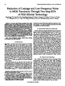
First,the monotonic relationship between FD signal level A and response degradation &(A) was experimentally confirmed. In this experiment, h ( A ) ’ s were calculated by (9) with fixed FD signal levels A of +20 dB to -40 dB, where the FD signal levelswere represented relative to the received noise level. Then, the response degradation D1(A)’s were measured for h ( A ) ’ s at each FD signal level A . This experiment was conducted under the four environmental conditions shown in Table I. Fig. 6 showsthemeasured relationship between FD signal level A and response degradationD1(A). Individual curves correspond to the conditions in TaIV.EXPERIMENTALRESULTS ble I. The monotonic relationship between A and &(A) A. ExperimentalConditions can be seen in these curves. Also, these relationships can Several experiments were conducted to confirm the ef- be seen to depend upon the experimentalconditions. Fig. 7 shows the frequency response to thedesired sigficiency of theAMNOR criterion and to evaluate the performance o f the AMNOR system. The experimental en- nal of each noise reduction filter derived at the fixed FD vironment is shown in Fig. 5(a) and (b). The microphone-signal levels of +20 dB, - 10 dB, -20 dB, and - 30 dB in Table I. The response degradation array consisted of four omnidirectional microphone ele-, under condition ments embedded in a plane baffle, as shown in Fig. 5(a). value Dl for each curve was 0.0, 0.1, 0.3, and 0.53. Fig. 8 shows the relationship between FD signal level Three of them were positioned on the circumference of a circle whoseradius was 8.5 cm and one was placedat the A and the improvement in SNR attained by FCV h (A) for each FD signal level. SNR was derived from the ratio of center,asshown in Fig. 5(b). Twoloudspeakerswere
@-a
@-a
0
A S P - 3 4 . NO. 6. DECEMBER 1986
IEEETRANSACTIONSONACOUSTICS.SPEECH,ANDSIGNALPROCESSING,VOL.
1396
TABLE I ENVIRONMENTAL CONDITIONS
Noise Source NoiseDistance Desired Signal from Source Direction Source Direction 0,
Condition -60"
0 0 0 0
45" 45 45 45
Microphone-Array" rl
OS
0.5 m
- 60" - 60" 40"
. I m
2m Im
"Desired signal source distance from microphone-array r, = 0.5 m.
tio of SNR obtained with the noise reduction filtering and SNR obtained without noise reduction filtering. The experimental conditions for curves @-@ are shown in Table I. From the results in Fig. 8, it can be seen that the SNR tended to improve as FD signal level A decreased. OJ VI
c
0
c VI
0
C Y
FD s i g n a l level A
(dB)
Fig, 6 . Relationship between FD signal level A and response degradation DIM).
Frequency
[kHz 1
Fig. 7. Frequency response to the desired signal under condition 0: @ FD signal level A = +20 dB, response degradation D, = 0.0. @ A = -lOdB,D~=0.1.@A=-20dB,D~=0.3.@A=-30dB,D~= 0.53.
FD signal level A
(dB)
Fig. 8. Relationship between FD signal level A and the improvement of SNR.
the microphone-array system outputpower when 3003000 Hz band-limited white noise was emittedfrom loudspeaker 2 (desired source), and output power when the same white noise was emitted from loudspeaker 1 (noise source). The improvement in SNR was defined as the ra-
C. Experiment 2: Propriety of AMNOR Criterion for Speech Signal Processing In this section, experimental results are presented which demonstrate propriety of the AMNOR criterion in comparison to that of conventional criteria for speech signal noise reduction. The received speech signal was simulated on a computer and added to the actually received noise signalswith various SNR values. Signal conditions for this experiment are given in Table 11. Noise-added-speech-signals were processed using the h(A)'s derived in experiment 1 for each corresponding environment condition and for fixed FD signal levels. Then, subjective pair-comparison tests were carried out using 16 listeners. The tests' results were transformed into psychological scale values according to Thurstone's case5 [lo] and normalized by subtracting the most preferable signal's value from the resulting scale values for each signal condition. The vertical axis in Fig. 9 shows the relative preference scale value; the higher the value, the more preferable. The horizontal axis shows FD signal level A . Solid lines indicate that the differences betweenadjacentpreference scale values (data points) are significant at the 90 percent confidence level. The dotted lines indicate that such a difference is not significant. The most preferable signal, in the experimental conditions (la) and (lb), was obtained at an FD signal level of A = -20 dB, and at A = - 10 dB in the experimental condition (4). This result indicates that the most preferable FD signal levels did not depend on the S/N ratios of the received signals but rather on the environmental conditions. Then, the optimal FD signal level A^ based on the AMNOR criterion with B, = 0.3 is determined according to Fig. 6. This is done by finding the FD signal level A at which the curve of D,(A) takes the value of 0.3. The derived is -20 dB for environmental condition@ and -3 dB for@. These results closely match the most preferable
a
KANEDA AND OHGA:ADAPTIVE
1397
MICROPHONE-ARRAY SYSTEM E=0.5 f o r l a E=0.1 f o r lb
TABLE 11 SIGNAL CONDITIONS FOR EXPERIMENT 2 Environmental SNR
of Speech Signal
Condition Condition 0 dB f 2 0 dB
0 dB FD signal level A
[dB)
Fig. 10. Relationship between FD signal level A and mean-square error in processed speech signals.
B
-2.01
20
rD
0
-20 s i y n o l level A (dB!
I
Fig. 9. Results of pair-comparison tests which were carried out to find the most preferable FD signal levels.
FD signal levels on the subjective test derived from Fig. 9. Next, suppose a distortionless constrained LMS criterion is adopted. Then an FDsignal level higher than +20 dB or more must be chosen because distortionless means Dl = 0 and Dl@) is the monotonically decreasing function between 0 and 1. In this case, however,it can be seen from Fig. 8 that the improvements in SNR are not so large, and from Fig. 9 that the preference values are very low. These results indicate that high SNR speech with some degradation .is preferred to low SNR distortionless speech, therefore indicating the propriety of the AMNOR criterion in comparison to the distortionless constrained LMS criterion. Themean-square errors of the noise reducedspeech signals from the original speech signal are now calculated in signal conditions (la) and (lb). The vertical axis in Fig. 10 shows the mean-square error, and the horizontal axis shows the FD signal level A . It can be seen that the minimummean-squareerror in these processedspeech signals can be attained at an FD signal level of A = - 30 dB for experimental condition (la) and at A = + 10 dB for condition (lb). The mean-square errors greatly depend on the SNR of received signals, and a high FDsignal level must be chosen when the SNR is high and vice versa to minimize mean-square error. This is because,in the high SNR case, maintaining a small degradation in the high level desired signal is more effective in improving the mean-square error than reducing the low level noise component. However, the subjective test results show that the most preferable FD signal levels do not depend on the SNR of the received signal. These results also indicate the propriety of theAMNORcriterion. , Of course, it is impossible to state from the fewexperimental results mentioned above that the optimal thresh-
old value dl for AMNOR signal processing is 0.3. However, itcan be concluded that the AMNORcriterion given above can produce a more suitable noise reduction filter for the human auditory system thanconventional filter criteria can.
D. Experiment 3: AMNOR System Performance In this section, the extent of the AMNOR system’sability to reduce noise will be demonstrated under the environmental conditions shown in Fig. 5 where rl = 0.5 m, r2 = 0.5 m, %N = 45”,and BS = -60”. The FD signal level, initially set at 0 dB relative to the input noise level, was updated after every 32 input samples by a fixed increment AA of 0.5 dB. Convergence parameter k in (9) was set at 0.1. Fig. ll(a) and (b) showsthe learning curve: for the algorithm presented above when f i l = 0.1 and Dl = 0.3. The horizontal axis shows time in terms of the number of adaptation steps and the vertical axis shows response degradation D l and output noise power D2 relative to the input noise power. It can be seen that the fluctuation in Dl for f i l = 0.3 is larger than that for f i l = 0.1. This is thought to occur because the deviation in D , ( A ) , caused by the deviation in A , is larger at A ”, where D , ( A”) = 0.3, than at A ’ , where Dl@’) = 0.1, as can be seen in Fig. 6. Fig. 12 shows the frequency response of the AMNOR system for 6 , = 0.1. The response to noise [curve (a)] is lower than the response to the desired signal [curve (b)] by more than 15 dB at almost all frequencies. Fig. 13(a) shows the horizontal directivity pattern for the AMNOR system, which was linearly averaged over the frequency range of 300-3200 Hz. The system’s response to noise is low bothin the direct and reflected noise directions and high in the desired signal direction. Fig. 13(b) shows the vertical directivity pattern in the a-0 and p-0 planes. The subjective improvement in the SNR was measured. Human speech and noise were emitted at the same signal level (SNR = 0 dB) from loudspeaker 2 and loudspeaker 1, respectively. Then,the received signals were processed by the AMNOR system with f i l = 0.1. The processed speech was subjectively tested in pair-comparison ,tests, with nonprocessed speech (reference signal) at various SNR values: 10 dB, 15 dB, and 20 dB. The results
1398
IEEETRANSACTIONS
ON ACOUSTICS,SPEECH,ANDSIGNALPROCESSING,
VOL. ASSP-34, NO. 6, DECEMBER 1986
Dl
-5 0.6
-10
L r n
-15 1 .o
-20
L
2000
0
4000
5 10 15 20 25 Reference signal SNR (dB)
I
Nuirber uf o d o p t a t i o n S t e m
Fig. 14. Subjective improvement in SNR using the AMNOR system.
(a) D,
D"
0.4
-5
0.6
-10
0 dB
sult was in good agreement with the results of the objective measurements shown in Fig. 12.
V. DISCUSSION A. Array Geometry and Filter Tap Length 0.8 -1 5 1.0 -20 The method proposed in this paper can be applied to any arrangement of microphone elements. However, its Plumber of cdoptation stem noise reduction characteristics are related to the array ge(b) ometry and filter tap length. Although a theoretical invesFig. 11. Learning curves for the AMNOR system. (a) 8,= 0.1 (b) 8,= tigation of these relationships remains to be made, some qualitative features are discussed here. 0.3. In auniform linear array, it is well known that the space between microphone elements is related to the upper limit of the objective frequency range, and the array length is related to the directional resolution of its directivity pattern. Similar relationships might also hold for array geometry and array characteristics on multidimensional arrays.Therefore,increasingthenumber of microphone elements and array length improves the noise reduction characteristics, in general, although it also causes the enlargement of the whole processing system. 0 1 2 3 Determining the optimal arrangement of a given numFi-equency (kHz! ber of microphone elements is -an important problem. Fig, 12. Frequency response of the AMNOR system. (a) To loudspeaker 1 (noise source).(b) To loudspeaker2(desiredsignalsource). However, very few experimental studies have dealt with this problem. The microphone arrangement adopted in this paper (Fig. 5 ) is based on those results. REFLECTIVE The length filter tap relates the frequency resolution of the directivity pattern; in other words, thefilter tap length relates the number of independent frequency directivity patterns which are formed by the system. Therefore, the longer the tap length is, the better the performance is. e= 0" However, the incremental improvement in performance Oa 0 @ caused by the tap length enlargement, depends on the frequency characteristics of noise.
Ab
5P
Algorithm B. Adaptation In Section 111-D, it was described that the FD signal (a) (b) A was renewed after FCV h converges to h(A), and level Fig. 13. Directivity pattern of the AMNOR system. (a) Horizontal plane. this is a sufficient condition for algorithm convergence. (b) Vertical plane. However, it was determined experimentally that the algorithm was able to converge even when h and A were are shown in Fig. 14. The horizontal axis shows the SNR adapted simultaneously if their incremental parameter k for the reference signal and the vertical axis shows the in (9) and AA were chosen properly. Actually, in experiment 3 in Section IV-D, the value of A was adapted bepreference rate for the processed signal. The circles are experimental results and aleast-square fitted curve is fore h converged satisfactorily to h(A). The theoretical drawn according to the method in [l11. The subjective investigation of the necessary and sufficient condition for improvement in SNR was approximately 16 dB. This re- algorithm convergence, and the investigation of the con-
KANEDAMIFROPHONE-ARRAY AND OHGA: ADAPTIVE
1399
SYSTEM
vergence characteristics which depend on parameters k and AA, remain for future study. As for actual convergencetime, considering that experiments were conducted at an 8 kHz sampling rate, it can be seen from Fig. ll(a) and (b) that the algorithm almost converges within 500 ms. In the event that faster convergenceisrequired,the most promising solution would be to adopt a faster algorithm forcalculating h(A), e.g., the lattice based adaptive algorithm [12].
An algorithm forderivinganoptimal filter has been proposed. This algorithm utilizes preset data concerning the desired signal source direction andnoise data inwhich the desired ,signal is absent. The FD signal not only controls the tradeoff relationship, but also enables the system to utilize a recursive algorithm for calculating noise reduction filter coefficients and to estimate the frequency response degradation. It has been shown that an optimal noise reduction filter can be obtained by selecting an appropriate FD signal level. C. Comments on “Requirement 2 ” The superiority of the AMNOR criterion over convenIf “requirement l "(R-1) in Section III-B is strictly ful- tional LMS and constrained LMS criteria was then demfilled, then’ AMNOR performs effectively without “re- onstrated in subjective hearing tests. A subjective SNR quirement 2”(R-2). However, the desired signal source improvement of 16 dB was obtained for a noise source is usually ahumanbeing, who is never stationary but placed at a distance of 0.5 m from the microphone-array rather moves in a restricted area while talking. Therefore,which consisted of 4 microphone elements on an 8.5 cm it sometimes happens that the actual desired signal direc- radius circle. tion is slightly different from the direction where thearray system assumes the desired signal to be coming from (i.e., (R-1) is not strictly fulfilled). In this case, if the adaptaAPPENDIX A tion algorithm acts on the received signals which contain PROOFOF MONOTONICITY the desired signal,the algorithm will regard the actual deAs stated in Section III-B,themean-squareerror sired signal as the undesired signal due to the difference le(n)(2can be expressed as in arrival direction, thus forming a filter that cancels the desired signal. This is also a shortcoming in conventional Ie(n)I2 = D~ D ~ . (A-1) array techniques. Assume that A l and A2 are two different FD signal levels Some other solutioncould be applied to solve thisprobwith the relationship A l > A 2 . The filter coefficient vector lem, but requirement 2 is applied in this paper. If (R-2) is fulfilled, and no noise source exists closeto the desired (FCV) which minimizes the mean-square error le(n) l2 signal direction, then AMNOR forms a relatively broad when the FD signal level A = A , is expressed as h ( A l ) , directional beam toward the desired direction. Therefore, and as h(&) , when A = A2. Also, the response degradation is denoted as Dl(Aljand slight movement of the desired source does not seriously the output noise power as D2(A1)when FCV h(A,)is used, affect the processed results. and similarly, as Dl(A2) and D2(A2)when FCV h(A2) is To fulfill (R-2), it is desirable to detect the existenceof used. the desired signal. However, at present, the only reliable Since h(Al)minimizes the mean-square error expressed methods of fulfilling (R-2) are that the talker informs AMby (A-lj when the FD signal level isA I , the mean-square NOR manually, or that AMNOR instructs the talkerwhen error for the FCV h(A2)is greater than the minimum ernot to speak. The development of a sophisticated and roror, that is, bust method of detecting the presence of the desired signal will be the subject of future work. ’
-
+-
VI. CONCLUSIONS Similarly, In this paper, a new adaptive microphone-array system for noise reduction, the AMNOR system, was proposed. This system employs a new optimization,criterion called an AMNOR criterion. The system affords effective noise reduction over a satisfactorily widefrequency range using a small size microphone-array with a few elements. It has been shown that a tradeoff relationship exists in adaptive array processing between.the degradation D l ‘of the frequency response to the desired signal and the output noise power D,. A fictitious desired (FD) signal has been introduced to control this tradeoff. The basic idea of the AMNOR criterion is to minimize the output noise powerD2 while maintaining the response degradation Dl below apredetermined threshold value Since A: > 0, A ; > , 0, A l > A2, the following inequality 8,.The noise reduction filter in the AMNOR system is can be derived: Dl(A2) - Dl(A1) 2 0. (-4-7) criterion. derived this based on
1400
ON ACOUSTICS, SPEECH, AND SIGNAL PROCESSING,
IEEE TRANSACTIONS
Therefore, Dl(A2)
2
(A-8)
DI(A1).
Also, from A; > 0, and (A-7), the right-hand term in (A5 ) is positive, that is, DZ(A1) -
D2(A2)
(A-9)
1 0.
Therefore,
D2(A1) 2 D 2 V 2 ) . (A-10) Thus, if A I > A 2 , then D , ( A l ) 5 Dl(A2)and D2(A1)2 D2(A2).The monotonic relationships have been proved. Here, suppose &(Al) = D1(A2),then from (A-4) and (A-lo), D2(A1)= D2(A2).Because both Dl and D2 are quadratic functions of h, it is easily proved that both equality relationships hold if and only if there exists a FCV h, which minimizes both Dl and D2, i.e., D,(h,) = 0 and D2(h,) = 0. In other words, equality relationships in (A-8) and (A-10) can hold only when there exists an FCV h, which completely cancels out noise component without degradation in frequency response. APPENDIXB
PROOFOF OPTIMALITY Consider an FCVh’, using which response degradation 0;is smaller than D,(A). Also, assume that the output noise power Di when h’ is used, is smaller than or equal to D2(A). Then the following inequality can be written: A’
+- D l @ ) - D2(A) > A 2
*
0;
+ 0;. (A-11)
by the definition Of h(A)7h(A) the imum mean-square error, that is, A 2 D1(A) D2(A). This is a contradiction. Thus, Di is greater than &(A).
-
+
ACKNOWLEDGMENT, The authors would like to acknowledge Dr. F. Itakura, former Chief of the Speech and Acoustics Research Section, Electrical CommunicationLaboratories,NTT,for his thoughtful comments and encouragement during the course of this work; also K. Kakehi, Chief of the Audio Visual Perception and Cognition Research Group, ECL, NTT, for his diligent reading and comments on the paper.
REFERENCES [I]J. S. Lim and A. V. Oppenheim,“Enhancement and bandwidth compression of noisy speech,” Proc. IEEE, vol. 67, pp. 1586-1604, Dec. 1979.
VOL. ASSP-34, NO. 6, DECEMBER 1986
[2] F. Pirz, “Design of a wideband, constant beamwidth, array microphone for use in the near field,” Bell Syst.Tech. J . , vol. 58, pp. 1839-1850, OCt. 1979. [3] B. Widrow, P. E. Mantey, L. J. Griffiths, and B. B. Goode, “Adaptive antenna systems,” Proc. IEEE, vol. 55, pp. 2143-2159, Dec. 1967. [4] S. P. Applebaum, “Adaptive arrays,” IEEE Trans. Antennas Propagar., vol. AP-24, pp. 585-598, Sept. 1976. [5] L. J. Griffiths, “A simple adaptive algorithm for real-time processing in antenna arrays,” Proc. IEEE, vol. 57, pp. 1696-1704, Oct. 1969. [6] 0.L. Frost, 111, “An algorithm for linearly constrained adaptive array processing,” Proc. IEEE, vol. 60, pp. 926-935, Aug. 1972. [7] R. A. Monzingo and T. W. Miller, Introduction to Adaptive Arrays. New York: Wiley, 1980. [8] C. Y. Suen and R. D. Mori, ComputerAnalysisandPerception. ’ Boca Raton,FL:CRC Press, 1982. 191 B. Widrow et al., “Adaptive noise cancelling: Principles and applications,” Proc. IEEE, vol. 63, pp. 1692-1716, Dec. 1975. [lo] J. P. Gilford, PsychometricMethods. New York: McGraw-Hill, 1954. 1111 M. Nakatsui and P. Mermelstein, “Subjective speech-to-noise ratio asa measure of speech quality for digital waveform coders,” J . Acoust. Soc. Amer., vol. 72, pp. 1136-1144, Oct. 1982. 1121 L.J. Griffiths, “Adaptive structures for multiple-input noise cancelling applications,” in Proc. ICASSP, 1979, pp. 925-928.
Yutaka Kaneda (”80) was born in Osaka, Japan, on February20, 1951. He received the B.E.E. and M.E.E.degreesfrom Nagoya University, Nagoya, Japan, in 1975 and 1977, respectively. Since joining the Electrical Communication Laboratories, Nippon Telegraph and Telephone Corporation, Musashino, Tokyo, Japan, in 1977, he has been engaged in research on acoustic signal processing. He is now a Research Engineer of the Speech and Acoustics Research Section of ECL, NTT. Mr. Kaneda is a member of the Acoustical Society of Japan and the Institute of Electronics and Communication Engineers of Japan.
Juro Ohga was born in Tokyo, Japan, on August 10, 1941. Hereceived the B.E.E. degreefrom the University of Electro-Communications, Tokyo, in 1964, and the Dr. Eng. degree from Nagoya University, Nagoya, Japan, in 1985. He was at the Electrical Communication Laboratories, Nippon Telegraph and Telephone Corporation,Tokyo,Japan, from 1964 to 1985, working on electroacoustic apparatus, transducer material, and acoustic signal processing. He is presently the Assistant to the General Manager of the Customer Premises Equipment Division at Fujitsu Limited, Kawasaki, Japan. His current work involves acoustics for telephone systems. Dr. Ohga is a member of the Acoustical Society of Japan and the Institute of Electronics and Communication Engineers of Japan.