2454
IEEE TRANSACTIONS ON MAGNETICS, VOL. 46, NO. 6, JUNE 2010
Reduction Design of Vibration and Noise in IPMSM Type Integrated Starter and Generator for HEV Jae-Woo Jung1 , Sang-Ho Lee1 , Geun-Ho Lee1 , Jung-Pyo Hong1 , Dong-Hoon Lee2 , and Ki-Nam Kim3 Department of Automotive Engineering, Hanyang University, Seoul, Korea Motor R&D Center, S&T Daewoo Co., Ltd., Busan, Korea HEV System Engineering Team, Hyundai Kia Motors, Hwaseong, Korea Integrated starter and generator (ISG) is working as starter after vehicle idle stopping and generator during vehicle driving. When ISG works as starter to operate engine, ISG produces maximum power at the operating speed 4000 rpm to remove vibration of initial starting of the engine. In that time ISG produces whine noise which can be detected inside a vehicle. There are two methods to reduce the vibration and noise. One is improving the stiffness of stator and the other is reduction of electromagnetic exciting force. Although improvement of stiffness using mechanical design is utilized effectively to reduce whine noise, the electromagnetic design using the reduction of exciting forces is more reasonable in the same motor size. Because ISG produces torque ripple, radial force and tangential force on operating condition, this paper deals with the reduction design of electromagnetic exciting forces which affect the noise and vibration. Two design variables are selected to optimize the rotor shape especially geometry of flux barrier, and response surface methodology (RSM) is applied as an optimization method. Finally, quantity of the vibration and noise of optimized model are compared with prototype model, and the noise measured in the vehicle engine bay was reduced from 27 dB(A) to 25 dB(A). Index Terms—Integrated starter and generator (ISG) , interior permanent magnet synchronous motor (IPMSM), noise, radial force, tangential force, torque ripple, vibration.
TABLE I SPECIFICATIONS OF PROTOTYPE
I. INTRODUCTION
I
DLE STOP IS ONE of the most important functions in hybrid electric vehicle (HEV) driving in the downtown especially. Idle stop ceases the engine operation in order to eliminate emission when vehicle is temporally stopped. After the idle stop, engine is started automatically by electric motor which is called by integrated starter and generator (ISG) [1]. The operating speed is different between conventional engine starter and ISG which is rotating about 4000 rpm with maximum power because it operates engine to reach over the idle speed to avoid a vibration of initial starting of engine. In that time, whine noise can be detected inside a vehicle. This electric noise should be removed by the enhanced electromagnetic design and optimization [2]. There are two methods to reduce the vibration and noise. One is improving the stiffness of stator and the other is reduction of electromagnetic exciting force [3]–[6]. Improvement of stiffness is utilized effectively to reduce whine noise. However, this mechanical solution brings an increase in motor size. Therefore, reduction of electromagnetic exciting force is considered in this paper. Two types of exciting force are produced during operation of ISG which are global force such as torque ripple and local force that is including radial force and tangential force [7]. This paper deals with reduction design of vibration and noise of ISG by decreasing both global force and local force. Before improving design of ISG, we had an experiment with prototype to find source of vibration and noise. After analyzing the vibration and noise of prototype, we found that 36th harmonic component of exciting force was the source of vibration
Manuscript received November 01, 2009; accepted January 11, 2010. Current version published May 19, 2010. Corresponding author: J.-P. Hong (e-mail:
[email protected]). Color versions of one or more of the figures in this paper are available online at http://ieeexplore.ieee.org. Digital Object Identifier 10.1109/TMAG.2010.2041434
Fig. 1. Configuration of prototype.
and noise. Therefore, reduction of 36th harmonic component of exciting force is selected as an objective function of optimum design. Only two variables are selected to simplify the optimization, and response surface methodology (RSM) is applied as an optimization method [8]. After the optimization, experimental results of vibration and noise of designed model are compared with prototype to verify the design method. II. VIBRATION AND NOISE CHARACTERISTICS OF PROTOTYPE 1) Specifications of Prototype: The specifications of prototype, interior permanent magnet synchronous motor (IPMSM), are shown in Table I. Prototype consists of 6-pole and 36-slots, and is wound by distributed winding as shown in Fig. 1. Slot pitch of armature winding is set to 5 to obtain sinusoidal back electromotive force (EMF) [9]. In order to increase power density, permanent magnet of Nd-Fe-B type is inserted in the rotor. The rotor core below the permanent magnet is punched to reduce total weight of the rotor.
0018-9464/$26.00 © 2010 IEEE
JUNG et al.: REDUCTION DESIGN OF VIBRATION AND NOISE IN IPMSM TYPE INTEGRATED STARTER
2455
Fig. 3. Magnetizing current between the two materials.
torque, 2nd harmonic component of torque ripple and 6th harmonic component of radial, tangential force are matched with 36th harmonic component of the measured vibration and noise. III. OPTIMIZATION OF ROTOR SHAPE 1) Calculation of Local Force: Fig. 3 shows the magnetizing current between the two materials. As one of the method of magnetic force calculation, magnetizing current which exists on element boundary is used by equivalent magnetizing current (EMC) method, and it can directly calculate the electromagnetic on force which affects the surface of structure. The current the line forming element and can be written as (1) Fig. 2. Experimental result of prototype. (a) Position of accelerometer; (b) experimental result of vibration and noise. TABLE II HARMONIC ORDERS OF ELECTROMAGNETIC EXCITING FORCES
(1) and are the tangential components of magnetiwhere is the distance on element zation on element boundary and boundary (2)
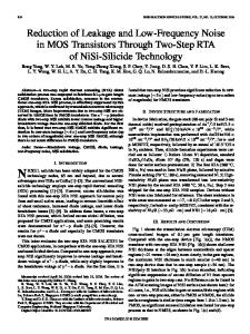
LCM : Least common multiple of number of pole and slot, pp: Pole pair N : Rotational speed of ISG, h: Harmonic order 2) Experimental Result of Prototype: The prototype mounted beside the engine is connected with shaft of engine by pulley, and experimental conditions and results are shown in Fig. 2. In order to measure vibration of prototype, 3 axis accelerometers are attached on the housing nearby cooling nipple in the radial direction and it is shown in Fig. 2(a). In addition, noise is measured 1 m away from the prototype in the direction of z axis using microphone. Fig. 2(b) shows color map of the measured vibration and noise of prototype. The vibration and noise are measured in the direction of x, y, and z-axis, and the trend of two results is almost similar in all directions. Because maximum torque is produced in the prototype rotation speed range from 1600 to 3000 rpm, the vibration and noise mainly occurred in this speed range. In addition, noise around 1.2 kHz after 2000 rpm in the direction of x axis is generated by resonance of engine assembly. Source of the vibration and noise is 36th harmonic component of electromagnetic exciting force. Therefore, the source should be removed by electromagnetic design and optimization of motor shape. Harmonic orders of electromagnetic exciting forces are shown in Table II. The fundamental component of cogging
The relationship in (2) holds for all materials whether they are linear or not [10]. Substituting (2) into (1) yields (3) shown below. (3) and are the tangential component of flux density where in each material. The electromagnetic force on the element boundary is written as (4) Flux density value of is given as the average value for each element. 2) Objective Function and Design Variables: Objective function and constraint condition of optimization using RSM based on analysis of experimental results of prototype are determined as followings: — Objective function 1) The reduction of 2nd harmonic component of torque ripple 2) The reduction of 6th harmonic component of radial and tangential force — Constraint condition (For power), (For control) Because peak to peak value of cogging torque is relatively smaller than peak to peak value of torque wave, the fundamental
2456
IEEE TRANSACTIONS ON MAGNETICS, VOL. 46, NO. 6, JUNE 2010
Fig. 4. Design variables for optimization.
TABLE III DESIGN AREA FOR OPTIMIZATION
Fig. 5. Comparison of rotor shape. (a) Prototype; (b) optimized model. Fig. 7. Comparison of electromagnetic exciting force. (a) Tangential force; (b) radial force; (c) torque ripple at maximum torque.
Fig. 6. Result of RSM (Optimal point calculated at 1000 rpm of motor).
component of cogging torque is excluded from the objective function. In order to reduce time consumption for the optimization, only two design variables, and , are selected as shown in Fig. 4. Design variable and are related with the pole angle and shape of flux barrier and their design area are shown in Table III. 3) Result of Optimization: In order to find optimal value of two design variables, the optimization using RSM is performed with using finite element analysis (FEA) [3]. The comparison result of rotor shape is shown in Fig. 5. The optimal values of design variables, and , are determined as 40.5 and 65.8 , respectively as shown in Fig. 6. The design variable is limited to 40.5 due to total harmonic distortion (THD) of back EMF, which is the constraint condition of optimization. In addition, although design area of for optimization is 55–64 , such a range of variable is automatically expanded by algorithm of
RSM leading to [8]. Finally, the shape of flux barrier which affects magnetic pole angle and leakage flux path is modified after the optimization. 4) Comparison of Electromagnetic Exciting Force: Torque versus operating speed is changed to meet constant power characteristics of prototype. Therefore, radial force and tangential force are calculated with several operating speed. The 6th harmonic component of radial force and tangential force which are expected as electromagnetic exciting forces of the vibration and noise are reduced as shown in Fig. 7(a) and (b). In addition, torque ripple of the optimized model is reduced to the half value of prototype as Fig. 7(c). IV. EXPERIMENTAL RESULT In order to verify the validity of design method studied in this paper, the vibration and noise experiment is performed. Firstly, motor’s ‘product-level’ experiment is performed. Secondly, ‘vehicle-level’ experiment is conducted to verify ultimate effect of motor on vehicle in reality. Fig. 8 shows the ‘product-level’ experimental setup with the optimized model. The prototype is connected with dynamometer by pulley. Two of G sensors (accelerometer) are attached on ISG which is shown in Fig. 2(a). The experiment is performed at the ISG speed of 1000 rpm and 3000 rpm because the vibration and noise is maximized in the range from 1000 rpm to 3000 rpm. In the vehicle driving, maximum torque and power are produced at 1000 rpm and 3000 rpm, respectively.
JUNG et al.: REDUCTION DESIGN OF VIBRATION AND NOISE IN IPMSM TYPE INTEGRATED STARTER
2457
Fig. 8. Experimental setup. Fig. 10. “Vehicle-level” experiment result of vibration and noise.
experimental result of prototype and investigating the source of vibration and noise, optimal design is performed to minimize electromagnetic exciting forces which are 2nd harmonic of torque ripple and 6th harmonic component of radial force and tangential force. Both ‘product-level’ and ‘vehicle-level’ experiments are performed for optimized model and prototype. As a result, vibration and noise of optimized model is successfully reduced compared to that of prototype model. REFERENCES Fig. 9. Experimental result of ISG acceleration. (a) Total value of acceleration; (b) 36th harmonic value.
Fig. 9 shows comparison of acceleration between the prototype and optimized model. The vibration of optimized model is entirely lower than prototype. In addition, total value of acceleration and the 36th harmonic component of acceleration value exhibit similar trend. Thus, the main source of entire vibration is the 36th harmonic component. “Vehicle-level” experiment is also performed. In this experiment, the engine of HEV is started by ISG after idle stop. Fig. 10 shows the experimental results of designed model and prototype. Similar to “product-level” test result, vibration and noise are also reduced in “vehicle-level” experiment. Vibration is reduced by 5 dB and noise is reduced by 2 dB(A), which is considered as A-weighting [11]. In other words, vibration and noise of optimized model is reduced to half value of prototype. V. CONCLUSION This paper introduces the reduction design of the vibration and noise in IPMSM type ISG for HEV. Characteristics of the vibration and noise can be reduced in the magnetic circuit design by reducing electromagnetic exciting force. After analyzing the
[1] G. Friedrich and A. Girardin, “Integrated starter generator,” IEEE Ind. Appl. Mag., vol. 12, no. 4, pp. 26–34, Jul./Aug. 2009. [2] S.-I. Kim, G.-H. Lee, J.-P. Hong, and T.-U. Jung, “Design process of interior PM synchronous motor for 43-V electric air-conditioner system in hybrid electric vehicle,” IEEE Trans. Magn., vol. 42, no. 4, pp. 1590–1593, Jun. 2008. [3] J.-P. Hong, K.-H. Ha, and J. Lee, “Stator pole and yoke design for vibration reduction of switched reluctance motor,” IEEE Trans. Magn., vol. 38, no. 2, pp. 929–932, Mar. 2002. [4] C. C. Hwang, S. P. Cheng, and C. M. Chang, “Design of high-performance spindle motors with concentrated winding,” IEEE Trans. Magn., vol. 41, no. 2, pp. 971–973, Fbr. 2005. [5] G. Henneberger, P. K. Sattler, and D. Shen, “Nature of the equivalent magnetizing current for the force calculation,” IEEE Trans. Magn., vol. 28, no. 2, pp. 1068–1072, Mar. 1992. [6] I. Hirotsuka, Y. Tsubouchi, and K. Tsuboi, “Effects of slot combination and skew slot on the electromagnetic vibration of a 4 pole capacitor motor under load condition,” J. Electr. Eng. Technol., vol. 1, no. 1, pp. 85–91, Mar. 2006. [7] G. H. Jang and D. K. Lieu, “The effect of magnet geometry on electric motor vibration,” IEEE Trans. Magn., vol. 27, no. 6, pp. 5202–5204, Nov. 1991. [8] S.-I. Kim, J.-P. Hong, Y.-K. Kim, H. Nam, and H.-I. Cho, “Optimal design of slotless-type PMLSM considering multiple response by response surface methodology,” IEEE Trans. Magn., vol. 42, no. 4, pp. 1219–1222, Apr. 2006. [9] T. J. E. Miller and J. R. Hendershot, Jr., Design of Brushless Permanent Magnet Motors. New York: Oxford Magma Phys., 1995. [10] M. N. O. Sadiku, Elements of Electromagnetics. Oxford: Oxford Univ., 2001. [11] J. F. Gieras, C. Wang, and J. C. Lai, Noise of Polyphase Electric Motors. Boca Raton, FL: CRC press, 2006.